Embedded 101: Two Types of MCU Resets — Full Chip Reboot vs Subsystem Reset
This article explains two reset types of RP2040: full chip reset and independent subsystem peripheral reset, along with relevant reset signals.
COMPONENTS
PROJECT DESCRIPTION
【Preliminary Note】The original hardware example in this article was written based on the RP2040. The actual hardware used in this hands-on demonstration features the W55RP20 as the main controller chip. The circuit logic and UF2 flashing operation principles are universally applicable, with only the main controller model differing. The original chip model mentioned in the circuit descriptions below is provided for reference purposes only.
Reset
Reset is like the "emergency restart button" of a chip. When the chip program freezes, the power supply voltage is unstable, or a restart is required, the "reset" will return the chip (or some devices) to its initial state and resume operation. The reset of RP2040 falls into two scenarios:
"Chip-level reset" means resetting the entire chip;
"Subsystem reset" refers to resetting only certain peripherals individually without affecting the entire chip, which offers greater flexibility.
1. Chip-level reset
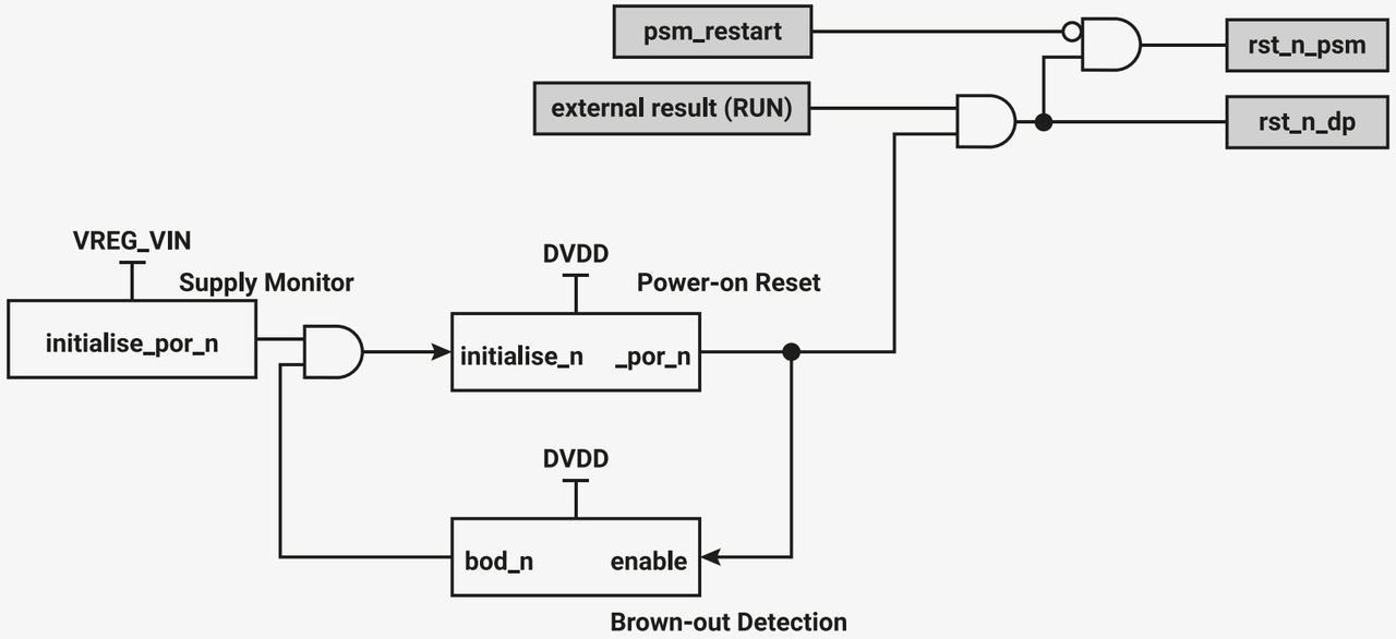
When the chip is just powered on, the supply voltage suddenly drops insufficiently (e. g., an unexpected power loss, also known as a "brown-out event"), the RUN pin is manually pulled low (equivalent to pressing the chip's "reset button"), or control is exercised via the debug interface, the "chip-level reset subsystem" will restore the entire chip to its initial state.
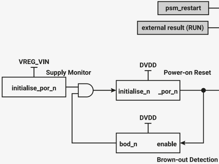
Figure 2.34 Logic Diagram of Chip Subsystem Reset Circuit
This subsystem has two "reset signals":
rst_n_psm: responsible for resetting the entire chip, while retaining the debug port (so that the debug device will not be reset, facilitating subsequent troubleshooting);
rst_n_dp: Only specifically resets the "Rescue DP (rescue debug port)".
These two signals are automatically triggered under the conditions of "just powered on, unstable power supply, and RUN pin pulled low". In addition, the rescue debug port can independently trigger rst_n_psm to reset the entire chip, while the rescue debug port itself will not be reset (which means "the rescue port can restart the chip while keeping itself running to facilitate subsequent debugging"). After the chip reset is completed, the boot process will be handed over to the power-on finite-state machine to continue.
2. Subsystem Reset
Apart from "full chip reset", the software can also independently control the reset of individual devices — such as USB controllers, PIO, and peripherals including UART, I2C, SPI, as well as components like PLL and ADC (these devices are not core components of the boot chip, and resetting them will not affect the entire chip).
These peripherals are in the "reset state" by default upon power-up (equivalent to being non-operational). When a specific peripheral is needed, the software manually releases it from the reset state to enable its operation. For example, if a UART malfunctions, there is no need to restart the entire chip — simply reset the UART, and all other devices will continue running. The base address of the registers that control these resets is 0x4000c000.
Figure 2.35 RP2040 Reset and Power-On finite-state machine