Serial Ports Explained Simply: Core Concepts With Real-World Examples
This tutorial explains UART asynchronous serial communication, frame structure, parity check, baud rate concepts and data transmission workflow.
COMPONENTS
PROJECT DESCRIPTION
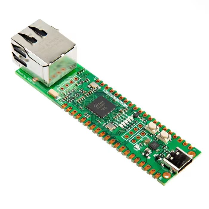
【Preliminary Note】The original hardware example in this article was written based on the RP2040. The actual hardware used in this hands-on demonstration features the W55RP20 as the main controller chip. The circuit logic and UF2 flashing operation principles are universally applicable, with only the main controller model differing. The original chip model mentioned in the circuit descriptions below is provided for reference purposes only.
1. Basic Concepts of Serial Communication
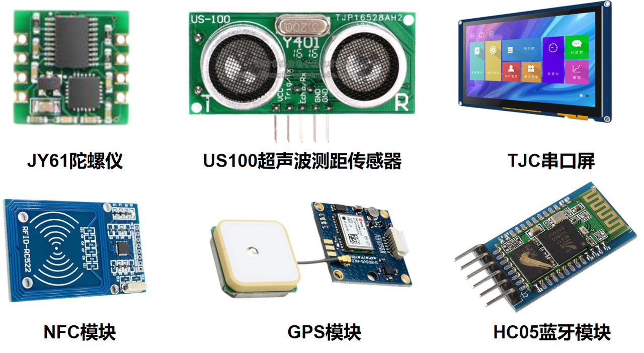
UART stands for Universal Asynchronous Receiver/Transmitter, commonly known as serial communication. It is one of the most widely used communication methods between devices. Despite its low communication rate, most electronic devices support it for data transmission, communication, control, simulation debugging and other operations thanks to its simple wiring and easy-to-understand protocol.Many devices or modules even provide dedicated serial ports for communication and control, such as GPRS modules, Bluetooth/WiFi pass-through modules, gyroscopes, LCD screens, etc.
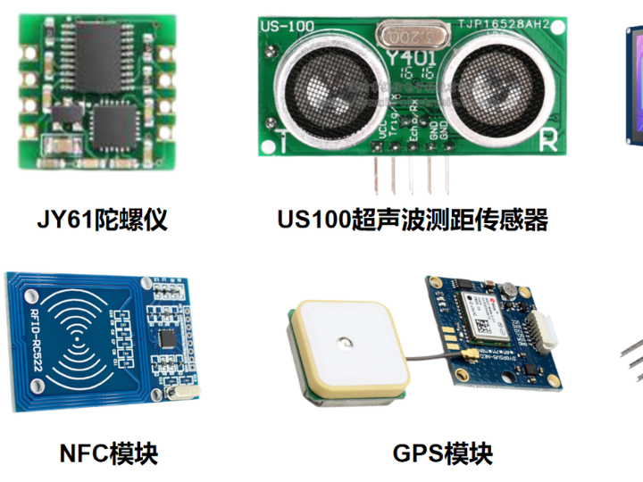
Some sensor modules supporting serial communication
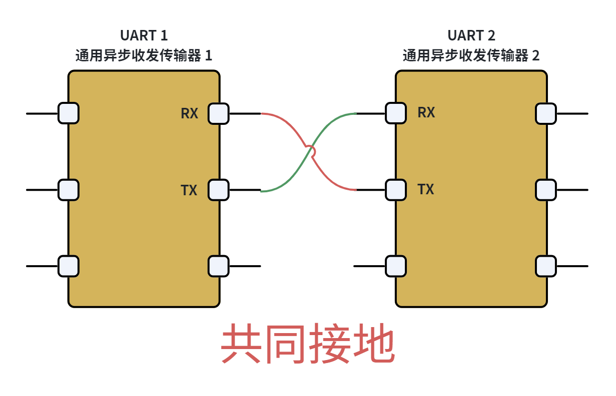
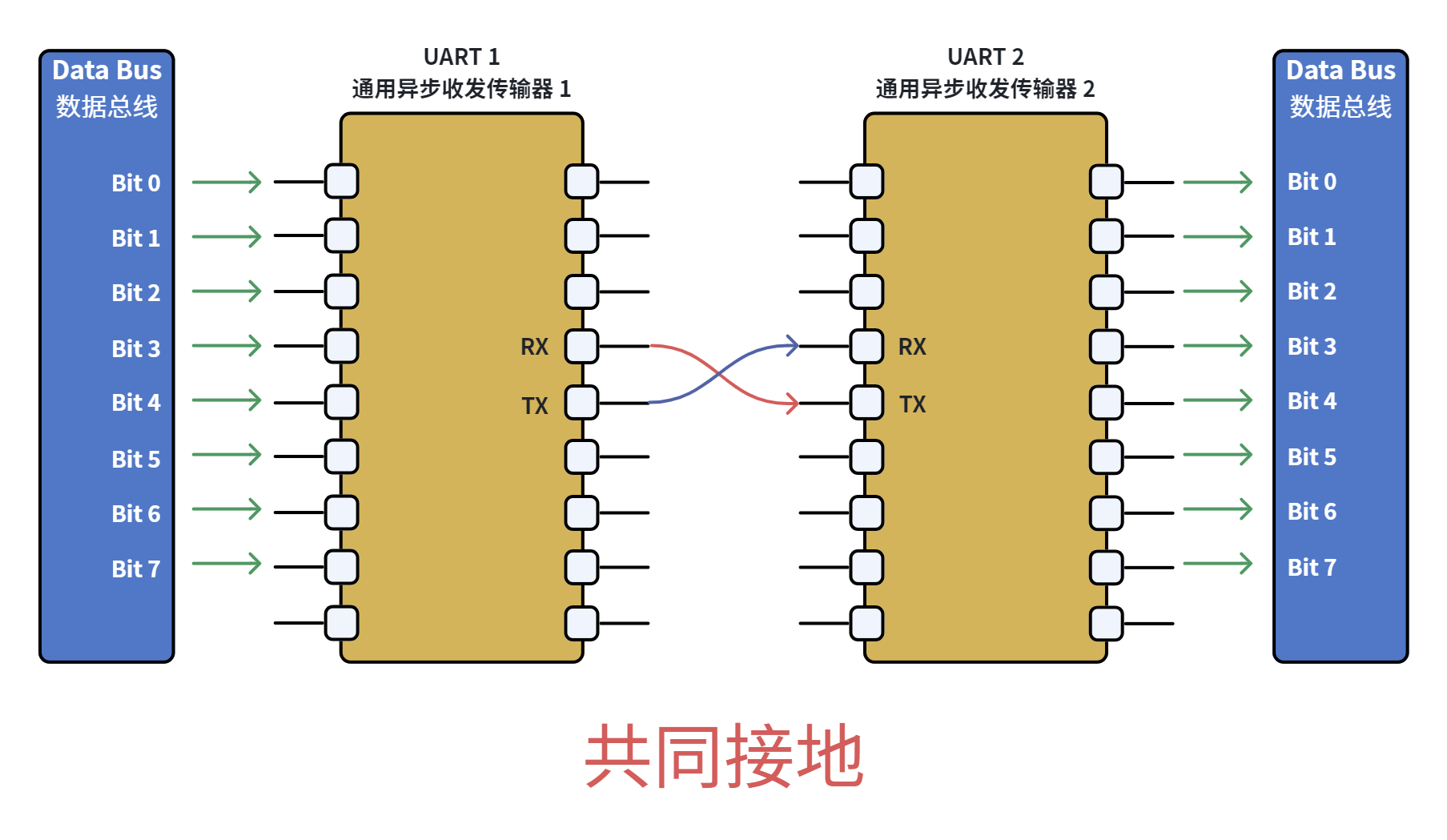
UART can implement full-duplex communication with only one data receiving line and one data transmitting line, adopting TTL/CMOS levels. Typical serial communication is completed with three lines, namely: transmitting line (TX), receiving line (RX) and ground line (GND). During communication, the TX and RX of the two parties must be cross-connected and the GND must be connected to enable normal communication, as shown in the following figure:
UART Serial Communication Hardware Connection Diagram
In the internal structure of the UART peripheral of a microcontroller, the data bus is connected in parallel with the generator/receiver of the serial port. Data is transmitted from the transmitter to the receiver in serial mode, and the receiver converts the serial data into parallel data for use by the receiving device.
The two devices are connected via a data bus and a transmitter/receiver of the serial port.
UART does not require an external clock line, but the two communicating parties need to agree on parameters such as start bit, body data, parity bit and stop bit for normal communication, making it an asynchronous communication method.
2. Serial Port Data Packet Format
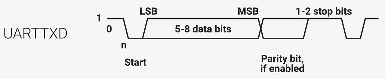
In UART, data is transmitted in the form of data packets. A data packet consists of a start bit, valid data bits, a parity bit and a stop bit. The data packet formats of the two communicating parties must be agreed to be consistent to transmit and receive data normally, and its composition is shown in the following figure:
The meaning of each bit and the optional parameters are as follows:
Start Bits / Stop Bits:
A data packet in serial communication starts with a start signal and ends with a stop signal. The start signal of a data packet is represented by one data bit of logic 0, while the stop signal of a data packet can be represented by 1 or 2 data bits of logic 1.
Data bits (valid data bits):
Immediately following the start bit of the data packet is the main data content to be transmitted, also referred to as valid data, and the length of the valid data is usually specified as 5,6, 7 or 8 bits.
Parity bits (校验位):
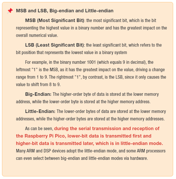
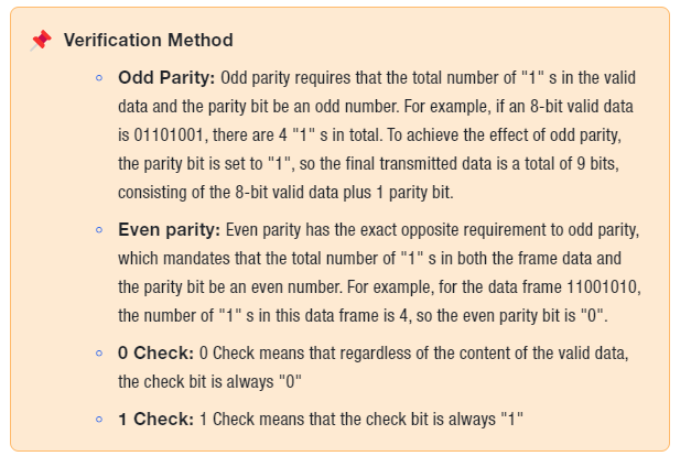
Following the valid data bits, there is an optional parity bit. Since data communication is relatively more vulnerable to external interference which may cause deviations in transmitted data, this issue can be addressed by adding a parity bit during transmission. The available parity methods include odd parity, even parity, space parity, mark parity and no parity.
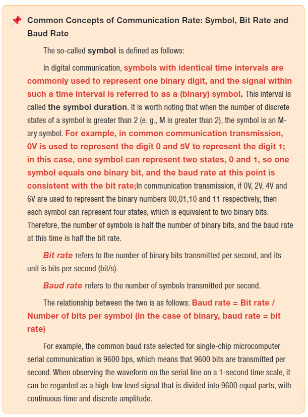
To ensure normal serial communication between two devices, in addition to setting the same parameters for each bit position, it is also necessary to correctly configure the baud rate of both devices, which refers to the length of each symbol for signal decoding. Common baud rates include 4800,9600,115200, etc.
3. Serial Port Data Transmission Process
Below, we will take the transmission and reception process of a data packet in the serial port as an example to explain the correct process of serial port data transmission:
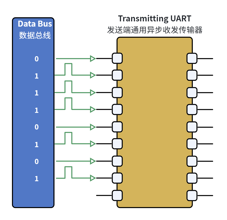
First, the data bus of the transmitting device transmits data to the serial port transmitter in a parallel manner:
The data bus at the UART transmitting end transmits data in parallel to the UART transmitter.
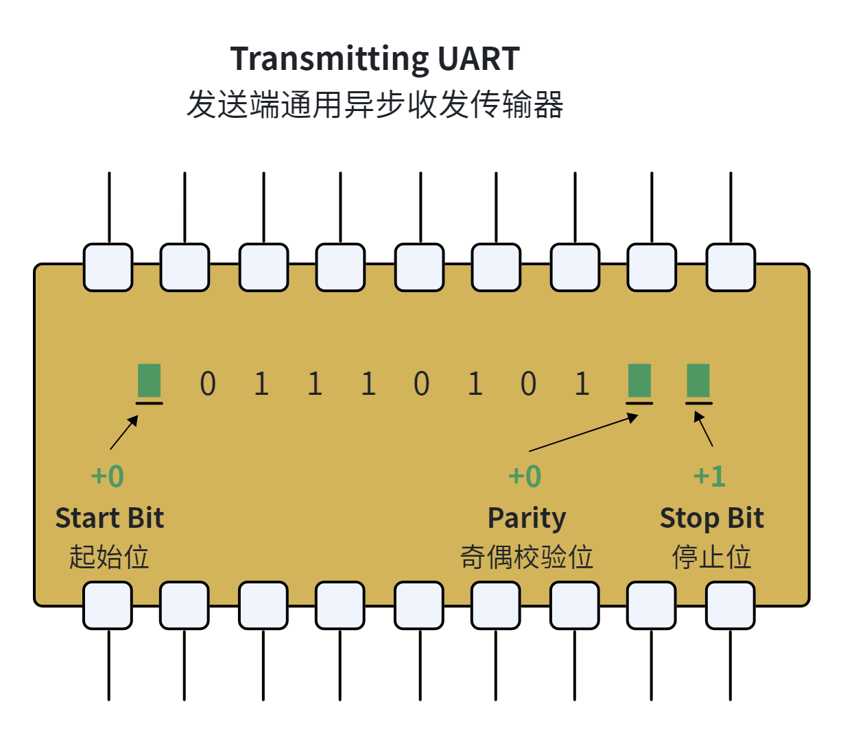
The serial transmitter adds a start bit, a parity bit, and a stop bit to the data frame:
Schematic diagram of data frame structure at UART transmitter
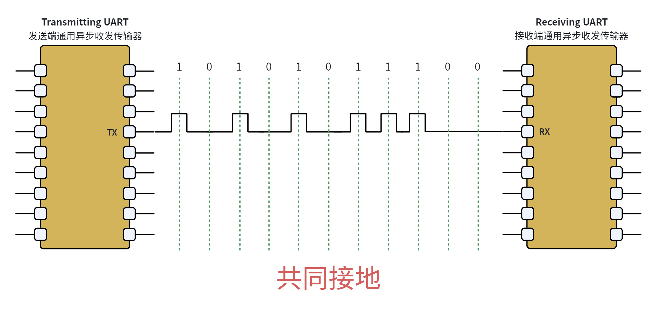
A serial port transmitter sends a data packet to the serial port receiver of another device, and the serial port receiver samples the data line at a preconfigured baud rate:
Hardware of UART Transmitter and Receiver Terminals and Signal Transmission
The overall process is shown as follows:
When not transmitting data, the serial transmission data line is normally held at a high level. To initiate data transmission, the serial transmitter pulls the transmission line from the high level to a low level for a duration of one clock cycle. When the serial receiver of the receiving device detects the transition from high voltage to low voltage, it starts sampling at the set baud rate frequency and reads the bits in the data frame:
Start bit of UART data frame structure
The data frame contains the actual data being transferred; if a parity bit is used, its length can be 5 to 8 bits, and if no parity bit is used, the data frame can be 9 bits long. In most cases, the data is transmitted starting with the least significant bit:
UART data frame structure data bits
After the serial port receiver of the receiving device reads the data frame, it counts the number of high-level values in the data frame and checks whether the total number is even or odd. If the parity bit is set to even parity, the total number of high levels in the data frame shall be even; if the parity bit is set to odd parity, the total number of high levels in the data frame shall be odd. Statistical Data
When the parity bit matches the data, the serial port receiver determines that the received data is correct; otherwise, the received data is erroneous (caused by factors such as circuit noise or transmission interruption).
Parity Bit in UART Data Frame Structure
To send a signal indicating the end of packet transmission, the serial transmitter pulls the data transmission line from a low level to a high level, maintaining this state for 1 to 2 clock cycles:
Stop Bits in UART Data Frame Structure
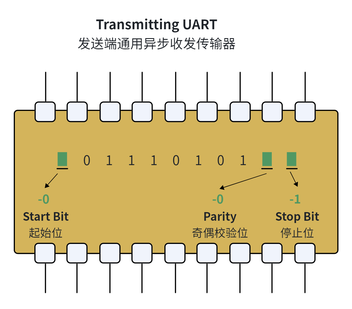
After the serial port receiver receives the entire data packet, it discards the start bit, parity bit and stop bit therein:
Schematic Diagram of Data Frame Structure at UART Receiver
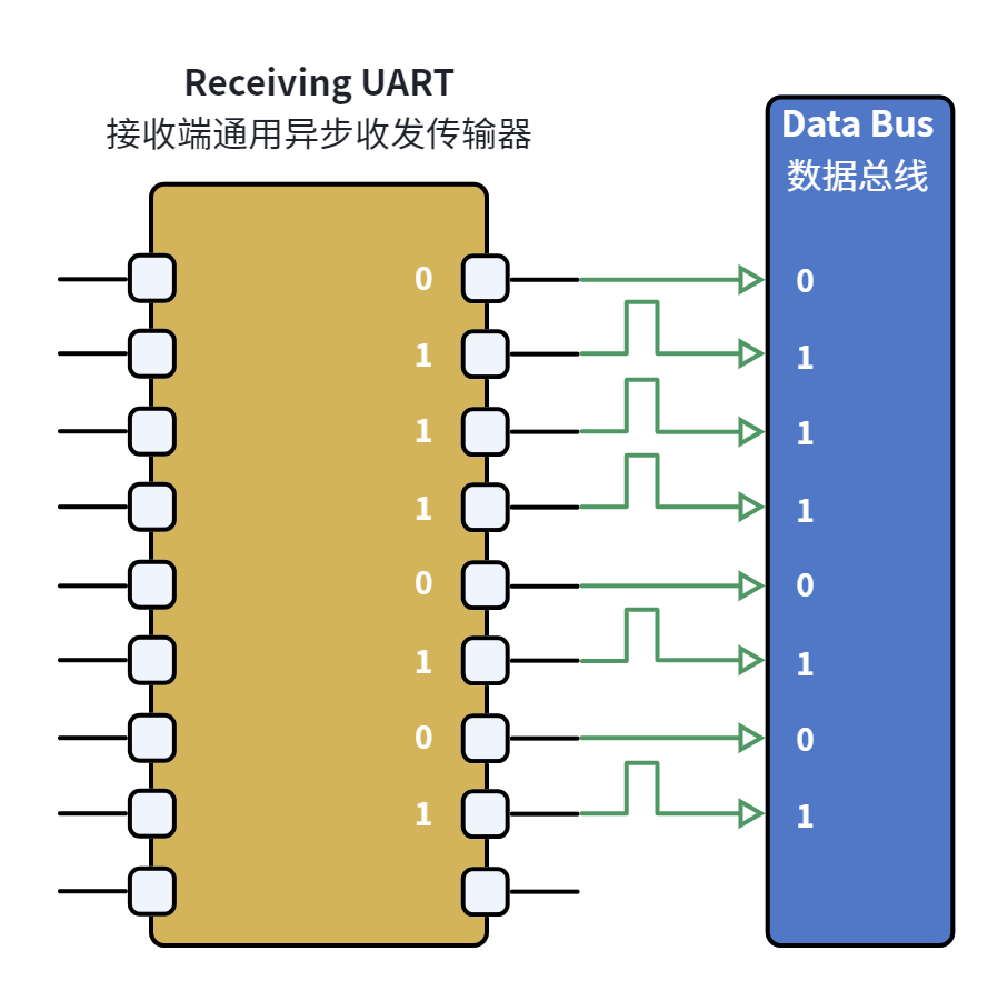
The serial port receiver converts serial data back into parallel data and transmits it to the data bus of the receiving device:
Data Parsing and Bus Transmission of UART Receiver