Serial Port Hidden Tips: 3 Concepts to Boost Communication Speed
This tutorial covers UART flow control, common data verification algorithms and pipeline optimization to boost serial communication throughput.
COMPONENTS
PROJECT DESCRIPTION
【Preliminary Note】The original hardware example in this article was written based on the RP2040. The actual hardware used in this hands-on demonstration features the W55RP20 as the main controller chip. The circuit logic and UF2 flashing operation principles are universally applicable, with only the main controller model differing. The original chip model mentioned in the circuit descriptions below is provided for reference purposes only.
1. Serial port flow control
"Stream" refers to "data stream". When the two communicating parties have mismatched rates (e. g., the processing speed of the receiving end is slower than that of the sending end), the buffer of the receiving end will "overflow", resulting in data loss. The core of "flow control" is to "enable the sending end to dynamically adjust its sending behavior according to the status of the receiving end".
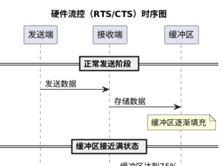
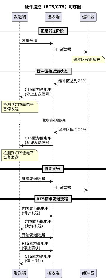
Hardware Flow Control: Controlled by dedicated pin signals, the most common type is RTS / CTS (Request To Send / Clear To Send) flow control. Its principle is that "the receiver uses CTS to inform the transmitter whether it can send data, and the transmitter uses RTS to request permission to send data".
The definitions of common signals are as follows:
RTS (Request To Send): A signal used by the transmitting end to request "permission to transmit" from the receiving end (for example, when an MCU sends a RTS low level to a "serial port module", it means "I am ready to receive, you may send data now").
CTS (Clear To Send): A response from the receiving end to the transmitting end indicating "permission to transmit"(for example, when a MCU receives a CTS low level signal from a serial port module, it means "I am ready to transmit, and you can receive").
Working Logic: The receiving end will set a "high buffer threshold (e. g., 75% buffer occupancy)" and a "low buffer threshold (e. g., 25% buffer occupancy)":
When the receiver buffer "≥ high level", set RTS to high level (meaning "my buffer is almost full, stop sending data"); when the transmitter detects the RTS high level, it will stop transmitting.
When the receiver buffer is "≤ low level", set RTS to low level (meaning "my buffer has space now, keep sending"); when the transmitter detects the low level of RTS, it resumes transmission.
Note: For hardware flow control, "both communication parties' hardware must support RTS / CTS pins", and "cross connection" is required during wiring (e. g. MCU ' s RTS connects to the serial module's CTS, and MCU 's CTS connects to the serial module' s RTS).
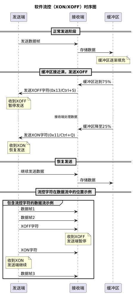
Software flow control:/ XON / XOFF characters (XON means "continue transmission", XOFF means "stop transmission").
Working Logic:
When the receiver buffer is "≥ high level", it sends to the transmitter the XOFF character (decimal 19, or Control-S); upon receiving XOFF, the transmitter immediately stops transmission.
When the receiver buffer is "≤ low level", it sends the XON character (decimal 17, or Control-Q) to the transmitter; upon receiving the XON, the transmitter immediately resumes transmission.
When the receiver buffer is "≥ high level", it sends to the transmitter the XOFF character (decimal 19, or Control-S); upon receiving XOFF, the transmitter immediately stops transmission.
When the receiver buffer is "≤ low level", it sends the XON character (decimal 17, or Control-Q) to the transmitter; upon receiving the XON, the transmitter immediately resumes transmission.
2. Data Validation
During transmission, factors such as electromagnetic interference and line loss may lead to " data bit errors ". "Data check" enables the receiving end to "detect and even correct errors" by "adding redundant information". Common verification methods are as follows:
Parity Check
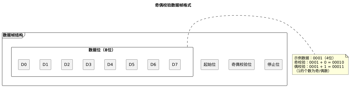
Principle: Append one parity bit after the "valid data", so that the number of 1s in the combination of "valid data + parity bit" meets the specified odd/even requirement.
Even parity: the number of 1s in "valid data + parity bit" is an even number (e. g., the valid data "0001" contains one 1, so the parity bit needs to be 1 → the total number of 1s is 2, which is an even number).
Odd parity: in the combination of "valid data + parity bit", the number of 1s is an odd number (e. g., the valid data "0001" contains one 1, so the parity bit should be 0 → the total number of 1s is 1, which is odd).
Features: It can only "detect 1-bit errors"; if multiple data bits go wrong simultaneously, the error may not be detected. Besides, it cannot "correct errors" and only supports "error detection".
CRC Check (Cyclic Redundancy Check)
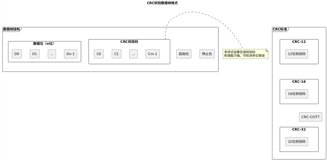
Principle: Based on the "division remainder" principle, a "polynomial operation" is performed on the "valid data" to generate CRC check code (which is sent along with the data); the receiving end repeats the same operation on the "received data", and if the "calculated CRC " does not match the "received CRC ", it is determined that the "data is erroneous".
Common Standards: CRC-12 (12-bit check code), CRC-16 (16-bit), CRC-CCITT (16-bit, commonly used in the communication field), CRC-32 (32-bit, commonly used for file verification).
Features: It has strong error detection capability, which can detect "multi-bit errors and burst errors", but it can only "detect errors" and cannot "correct errors".
XOR Checksum (XOR Check)
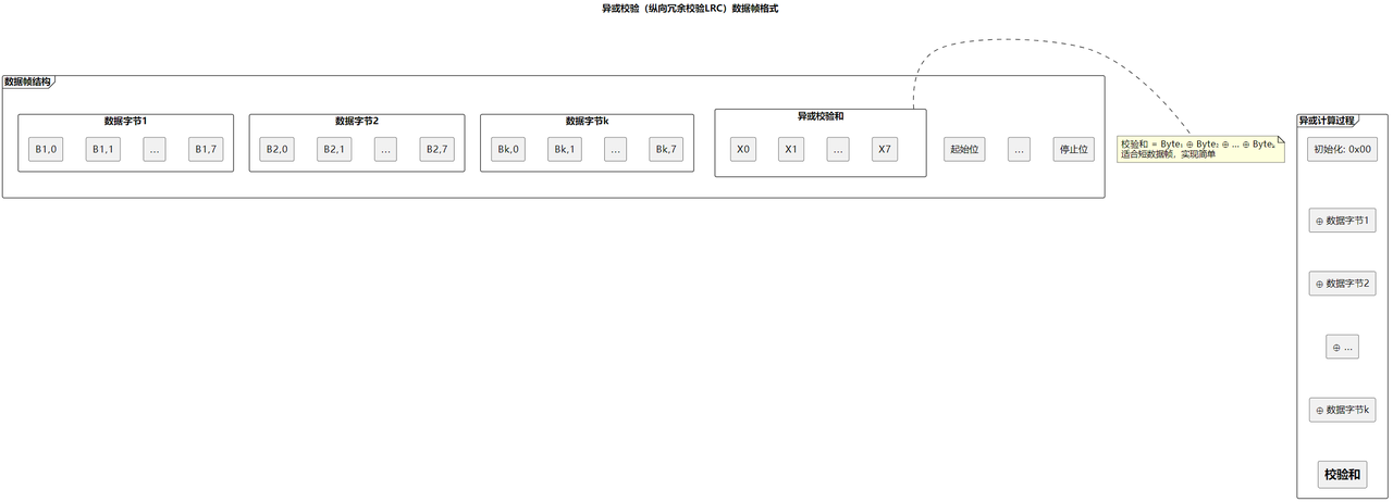
Principle: Perform a byte-wise operation on "all bytes of the data word" XOR operation to generate a 1-byte "checksum"(also known as "Longitudinal Redundancy Check, LRC").
Example: The data words are Byte₀, Byte₁, Byte₂, …, Byteₙ, and the checksum = Byte₀ ⊕ Byte₁ ⊕ Byte₂ ⊕ … ⊕ Byteₙ(where "⊕" denotes the XOR operator).
Features: It is easy to implement and suitable for scenarios featuring "short data and low power consumption"; however, its error detection capability is weaker than that of CRC, so it is mostly used in occasions where the requirement for reliability is not extremely high.
3. The "Pipeline" Idea for Improving Communication Throughput
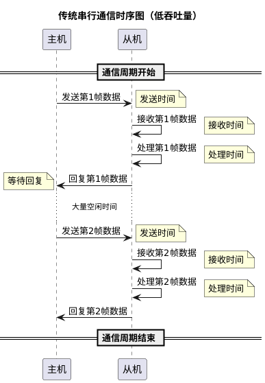
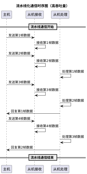
The " throughput " of serial communication refers to the "amount of data transmitted per unit time". The traditional serial process of "host send → slave receive → slave reply → host receive" will generate a lot of idle time due to "waiting for reply", resulting in low efficiency. Through "pipelining" transformation, throughput can be significantly improved.
Traditional Process vs. Assembly Line Process (Time Dimension Comparison)
Traditional process: The sender (master) sends "Frame 1" → the receiver (slave) receives "Frame 1" → the slave processes "Frame 1" → the slave replies with "Frame 1" → the master receives the reply → then sends "Frame 2". ..(there is a large amount of "red idle time" between each frame).
Pipelining Process: The sender does not need to wait for "the reply of the previous frame to be completed", and can continuously send "Frame 1, Frame 2, Frame 3.. ." as long as "the interval between adjacent frames is sufficient"; the receiver, on the other hand, "processes the received frames while receiving new ones"(similar to the "instruction pipeline" of a CPU).
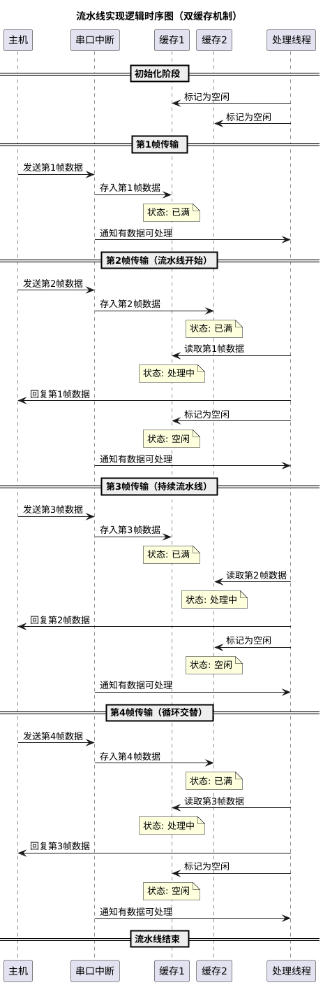
The implementation logic of the pipeline: "caching + task parallelism". To achieve parallelism between "receiving" and "processing", at least two cache spaces are required:
While "Buffer 1" is "receiving new data frames", "Buffer 2" can simultaneously "process the received old data frames".
The transmitter may also send the next frame without waiting for the receiver to finish replying, as long as the frame interval enables the receiver to "normally trigger interrupts and process data".
For higher efficiency, you may also manage multiple caches via queues (for instance, in real-time systems such as μC/OS-II, manage multiple caches with a combination of memory management and queue services), and it even supports the mechanism of urgent task preemption (inserting urgent communication tasks to the head of the queue for priority processing).