



RTC Real‑Time Clock Deep Dive: Structure, Accuracy, Error & Use‑Cases
Full guide for RTC: structure, accuracy, error and applications.
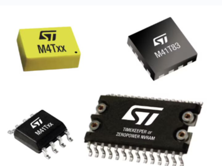
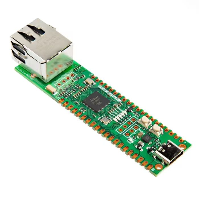
RTC(Real‑Time Clock)real‑time clock is a hardware module or chip that keeps track of current time. It is commonly used in devices requiring accurate time‑keeping such as embedded systems, computers and smart devices. The RTC module can continue counting time even when the main device is powered off, powered by a backup battery or supercapacitor.
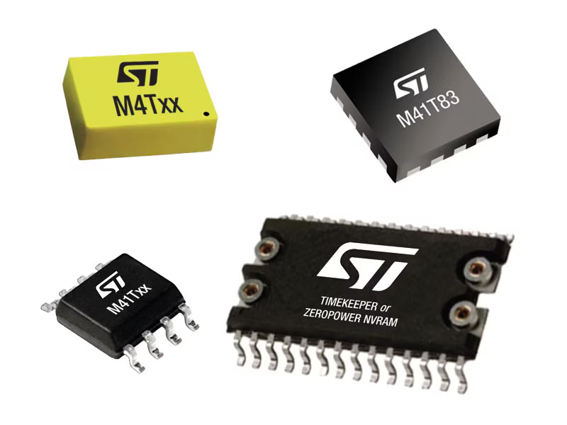
Common RTC real‑time clock chips
Simply put, an RTC (Real‑Time Clock) can be regarded as a timer with a fixed 1‑second tick interval, as shown in the figure below:
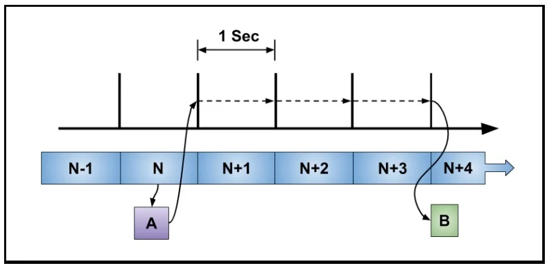
This diagram demonstrates RTC time‑counting and alarm functions. At point A the second counter is read, and an event B is scheduled to occur three seconds later. This operation is known as an alarm. Meanwhile the second counter runs continuously without stopping or resetting.
RTC real‑time clocks generally provide these functions:
Time keeping RTC records and continuously tracks seconds, minutes, hours, date, month, year and other time‑related information.
Low‑power operation RTC modules normally work in low‑power modes, making them well‑suited for long‑running embedded systems.
Alarm function Many RTC modules support alarm features, generating interrupt signals at preset times to trigger system actions.
Backup power supply support RTC modules are usually equipped with backup batteries or supercapacitors to maintain normal operation after main power is cut off.
Typical application scenarios:
Timestamp recording Record event timestamps for data acquisition, log‑keeping and other use‑cases.
Scheduled operations Trigger system actions at specified times, for example scheduled device power‑on or power‑off.
Calendar function Devices that need to display date and time such as clocks and calendars.
- RTC basic structure and working principle
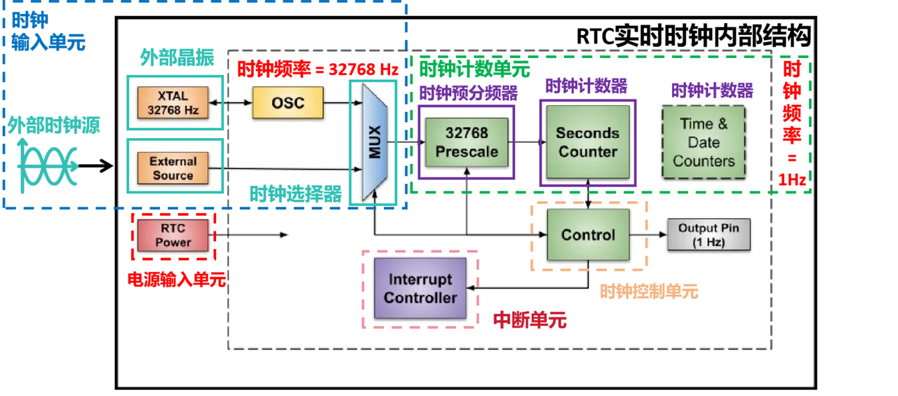
The basic RTC structure includes the following units:
Clock input unit Receives external clock signals, typically from a high‑precision 32768 Hz crystal oscillator or other external clock source. A multiplexer can select the clock source and feed it into the prescaler.
Power supply input unit Accepts main system power input and supports backup‑battery input, so time‑keeping continues when main power fails.
Interrupt unit Generates interrupt signals for time match and alarm events. Interrupts can wake‑up the system or trigger dedicated operations.
Clock control unit Handles clock configuration and control; allows setting current time and calendar values.
Clock counting unit The prescaler divides the incoming clock frequency by 32768 (2^15) to produce a 1‑second timebase. A typical RTC contains a 32‑bit (or wider) second counter. Some RTCs maintain separate counters for wall‑clock time and calendar dates. Counter values are stored in internal registers for read and write access.
Working principle summary: When system power is available, the RTC crystal starts oscillating and the counter circuit begins counting. The counter increments by one every second and updates time‑and‑date values inside registers. Current time values can be read or modified by accessing the clock counter registers.
When main power is lost, the RTC switches over to backup‑battery power and keeps counting time. Alarms can be configured to trigger interrupt signals at specified moments.
- RTC real‑time clock accuracy and error
Typical RTC crystal accuracy specifications range from ±20 ppm to ±100 ppm (parts‑per‑million). This translates to a daily time error between roughly ±1.7 seconds and ±8.6 seconds. (±100 ppm means the clock may gain or lose 100 seconds over one million seconds of runtime. For one day (86400 seconds), ±100 ppm yields approximately ±8.6 seconds of daily error.)
Concrete values:
±100 ppm daily time error ±8.6 seconds
±50 ppm daily time error ±4.3 seconds
±20 ppm daily time error ±1.7 seconds
These errors originate from intrinsic crystal‑oscillator properties including temperature drift, aging effects and external circuit influences. For high‑precision applications, lower‑ppm crystals are preferred. Designs may also implement temperature compensation or correct RTC drift with an external high‑accuracy time source.
- On‑chip internal RTC versus external RTC
Internal RTC An RTC peripheral integrated inside the microcontroller chip, usually driven by an on‑board 32.768 kHz crystal oscillator for time‑keeping. Its accuracy is affected by the main MCU clock and temperature. It is used for applications with relaxed accuracy requirements.
External RTC A dedicated stand‑alone real‑time clock chip independent of the MCU. It communicates with the MCU over I2C, SPI or other buses. It uses its own separate 32.768 kHz quartz crystal and has dedicated backup‑power circuitry. When main power is removed it immediately switches to backup power (commonly a CR2032 coin‑cell battery). Additional capabilities include alarms, timer interrupts and backup SRAM storage. It is used for use‑cases requiring high time accuracy and long‑term time preservation after power loss.
Important note: The RP2040 microcontroller on Raspberry Pi Pico does not feature traditional RTC power‑fail backup functionality. Unlike some MCUs such as STM32, there is no dedicated VBAT pin to keep the RTC running when powered down. Once power is disconnected, RTC counting stops and all time data is lost.