



RP2040 RTC Register Deep‑Dive: SETUP, IRQ, INTF Usage & Configuration
RP2040 RTC register analysis for SETUP, IRQ and INTF configuration
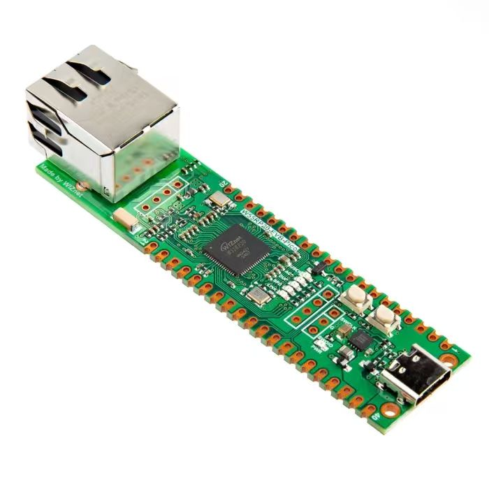
Introduction to RTC peripheral on Raspberry Pi Pico
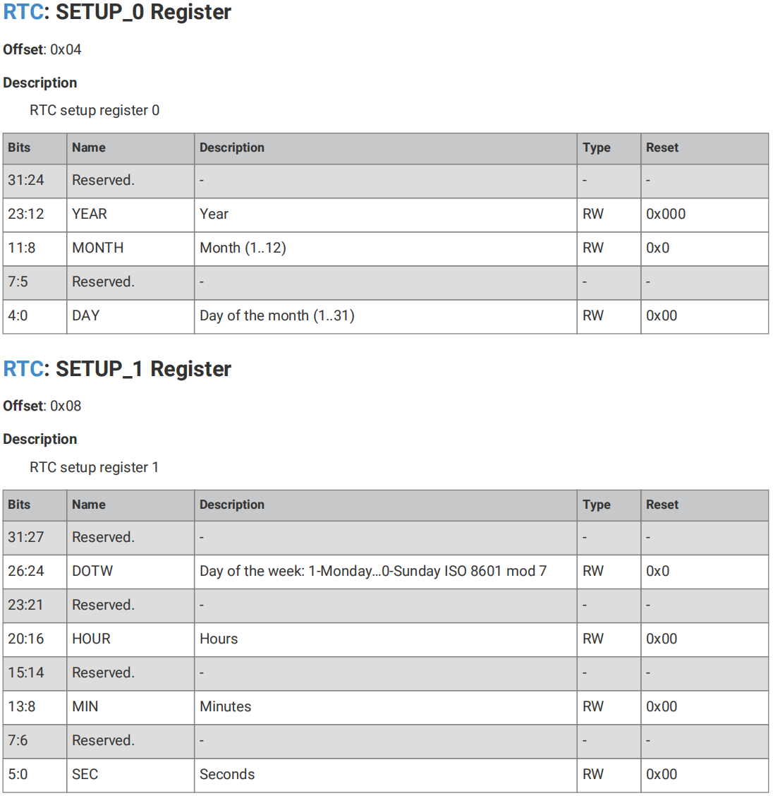
Time inside the Raspberry Pi Pico RTC peripheral is stored in binary format, separated into seven fields:
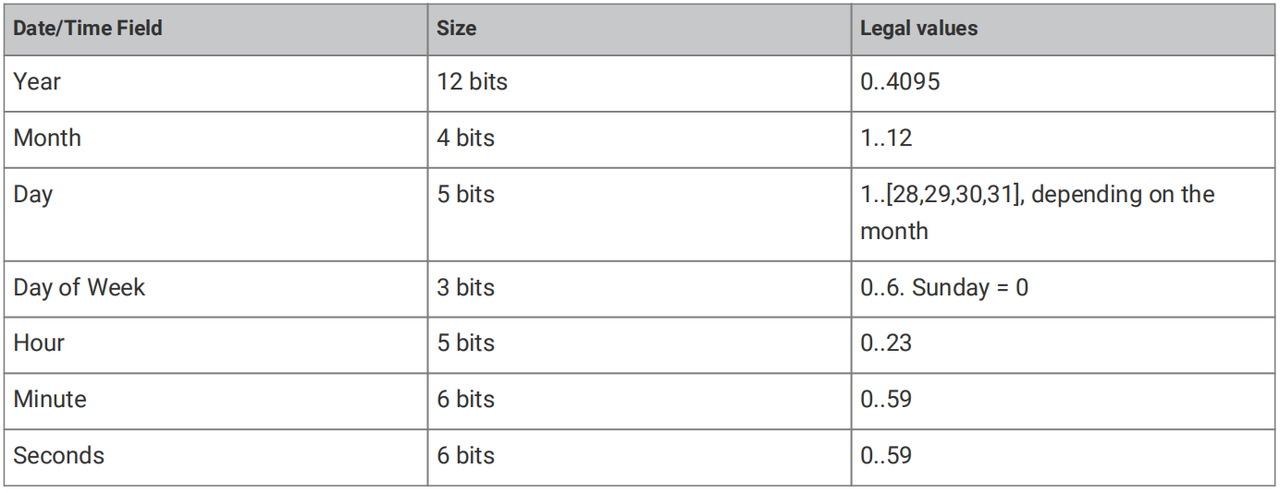
Note that these seven fields are both readable and writable. Pay attention to valid time‑value ranges when writing. The RTC does not validate whether programmed values fall inside legal ranges. Illegal values may cause unexpected behaviour.
Weekday is numerically encoded starting from Sunday (Sun): Sun=0, Mon=1, ..., Sat=6. This encoding follows ISO 8601 mod‑7 rules. The RTC has no built‑in calendar logic. It will not automatically calculate correct weekdays; it simply increments the stored numeric value. For example, if current weekday is Monday (1), the next tick becomes Tuesday (2), and so on.
Current time can be retrieved by reading the RTC_0 and RTC_1 registers:
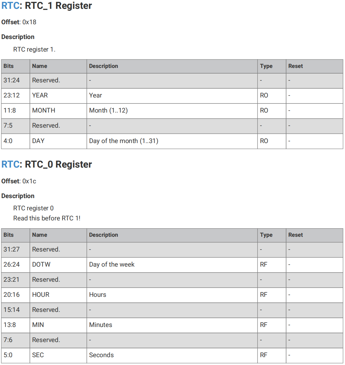
Time can also be configured via the SETUP register:
- RTC clock input
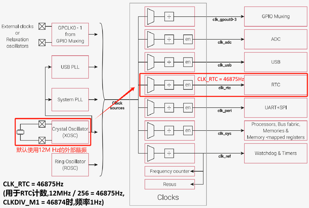
The reference clock used by the RP2040 (Raspberry Pi Pico) RTC peripheral is clk_rtc. Its frequency may be any integer value between 1 Hz and 65536 Hz. The internal 1 Hz timebase is generated by an internal clock divider which divides the clk_rtc frequency by an integer value. That integer minus one is written into register CLKDIV_M1:
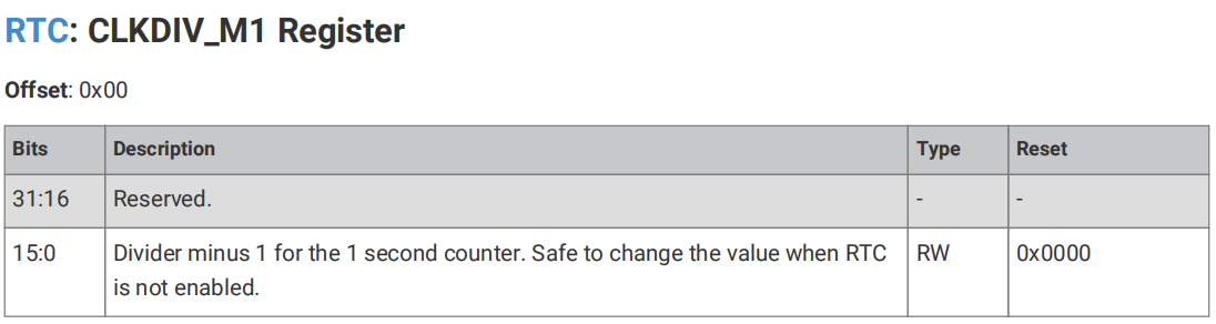
Important note: Changing CLKDIV_M1 while the RTC is enabled is not recommended. This modifies the RTC clock frequency and corrupts the accuracy of seconds, minutes, hours and other time units, introducing timing drift. Such drift is unacceptable for time‑critical applications.
clk_rtc may be driven by internal or external clock sources and can be pre‑divided by a fractional divider.
XOSC @ 12MHz / 256 = 46875Hz To obtain a 1 Hz reference clock under this configuration, CLKDIV_M1 shall be set to 46874. This uses the default 12 MHz external crystal oscillator.
External reference from GPS In this scenario GPS provides a once‑per‑second pulse. clk_rtc is configured to run from GPIN0 on GPIO pin 20. The clk_rtc pre‑divider equals 1, and the internal RTC clock divider is also 1, meaning CLKDIV_M1 is set to 0.
All read‑write accesses to RTC registers operate within the processor clk_sys clock domain. Data is synchronised across different clock‑domain boundaries. This means writes to RTC registers do not take effect immediately; synchronisation and update require two clk_rtc cycles. This behaviour must be considered especially when using slow reference clocks such as 1 Hz. Slow clock speeds introduce update‑latency which must not degrade system time accuracy during RTC feature design and implementation.
The crystal oscillator fitted on Raspberry Pi Pico is a 12 MHz SMD crystal manufactured by AEL (Advanced Electronics and Logistics):
The original datasheet could not be located. For reference we compare against the domestic equivalent Yangxing X322512MSB4SI crystal:
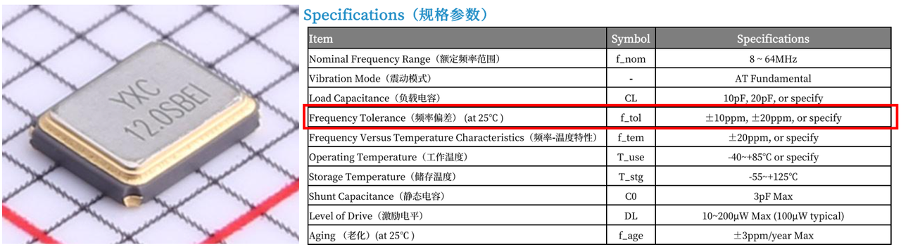
Its frequency accuracy is estimated at no worse than ±30 ppm, corresponding to a maximum daily time error of approximately 2.6 seconds.
- Leap‑year detection
Inside the RTC SETUP_0 register, leap‑year detection triggers when the YEAR bit‑field value is divisible by 4. Upon detection, February 28 rolls over automatically to February 29 instead of March 1:
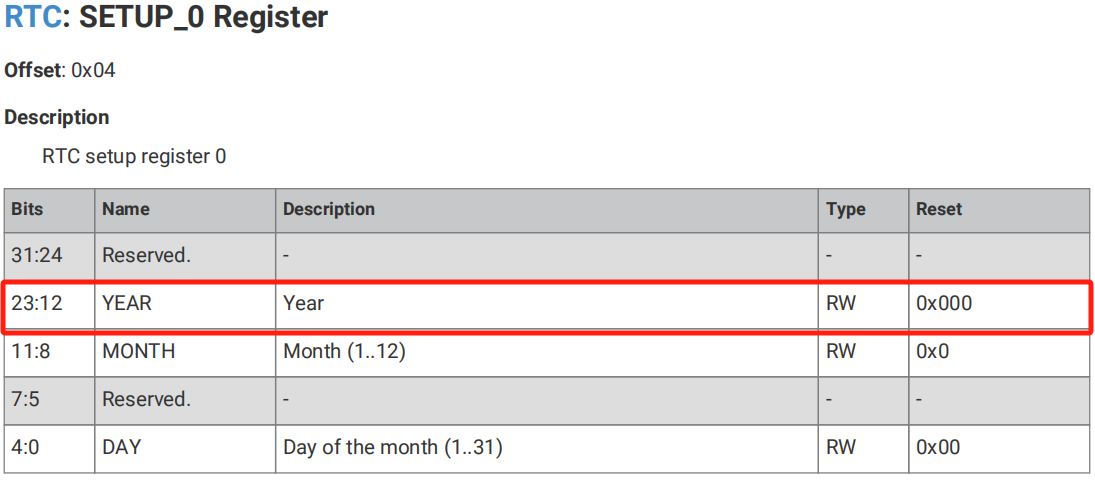
This simple divisible‑by‑4 rule is not universally correct and fails for century‑years such as 2100. To handle such cases, the RTC provides the CTRL.FORCE_NOTLEAPYEAR bit to forcibly disable leap‑year checking:
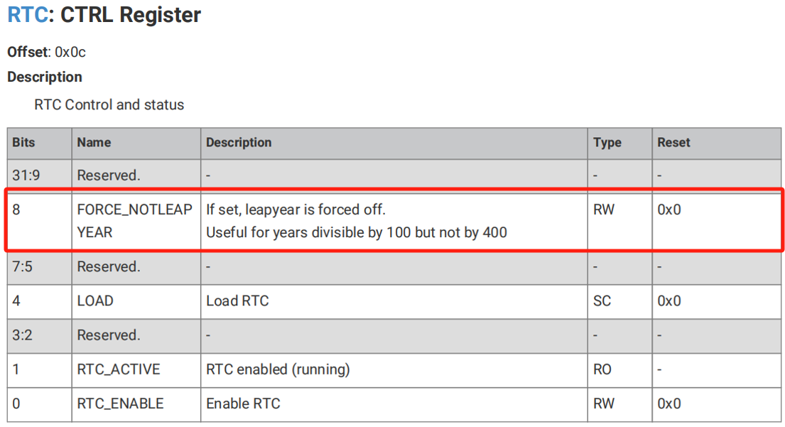
Leap‑year evaluation only occurs at 23:59:59 on February 28. If software identifies a given year as a non‑leap‑year, set the FORCE_NOTLEAPYEAR bit before that timestamp. This forces the calendar to skip February 29 and advance directly to March 1.
This forced leap‑year override is useful especially for dates after March 1 2096. Before 23:59:59 on February 28 2100, software must pre‑set FORCE_NOTLEAPYEAR so the RTC correctly processes this non‑leap‑year while accounting for cross‑clock‑domain update latency.
- Interrupt functionality
The RTC can generate interrupts at configured timestamps. The IRQ_SETUP_0 register contains the global MATCH_ENA enable bit to activate match‑interrupt functionality:
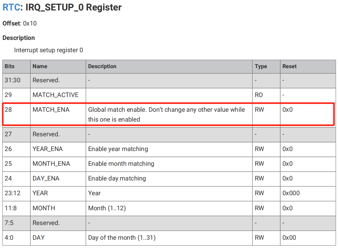
Separate enable bits exist for each time field (year, month, day, weekday, hour, minute, second). Developers can selectively enable interrupts on individual time‑fields to produce periodic interrupts at specified times:

Raw RTC interrupt status may be read from the INTR register, and masked interrupt status from the INTS register:
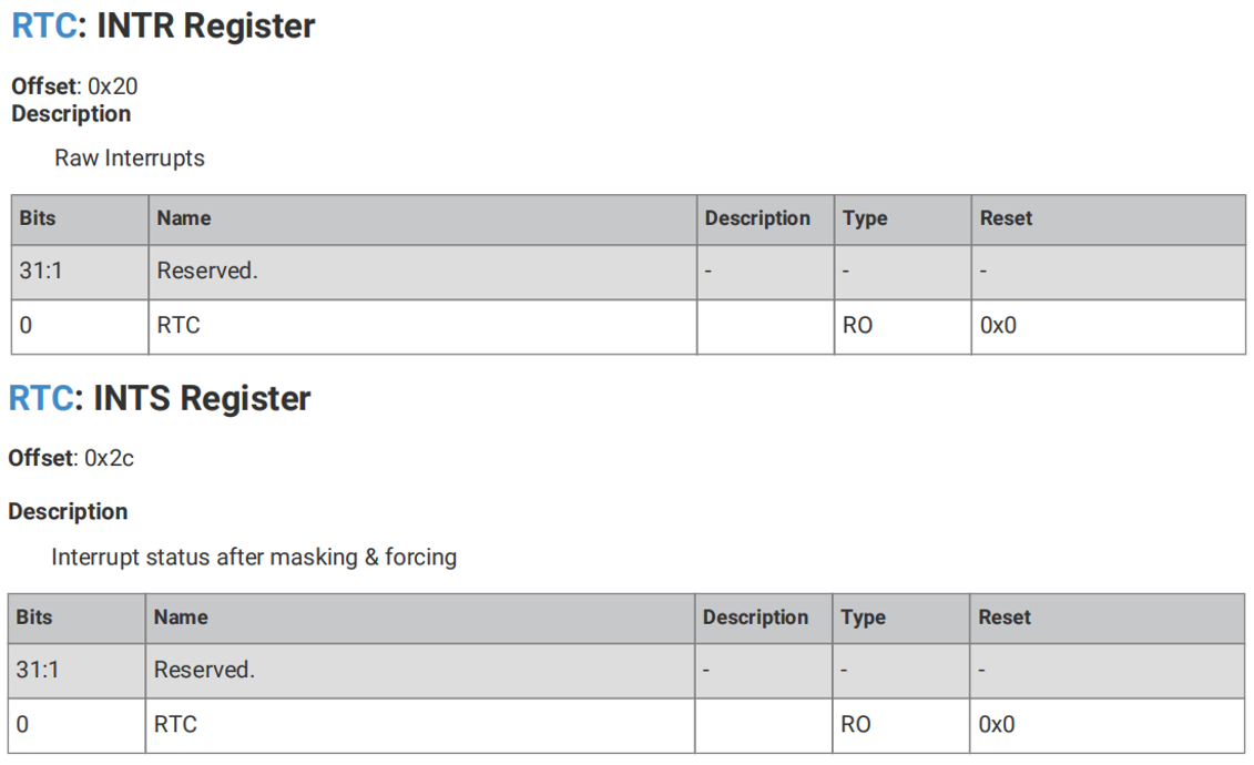
The INTF register can force‑trigger RTC interrupts, and the INTE register enables RTC interrupt outputs:
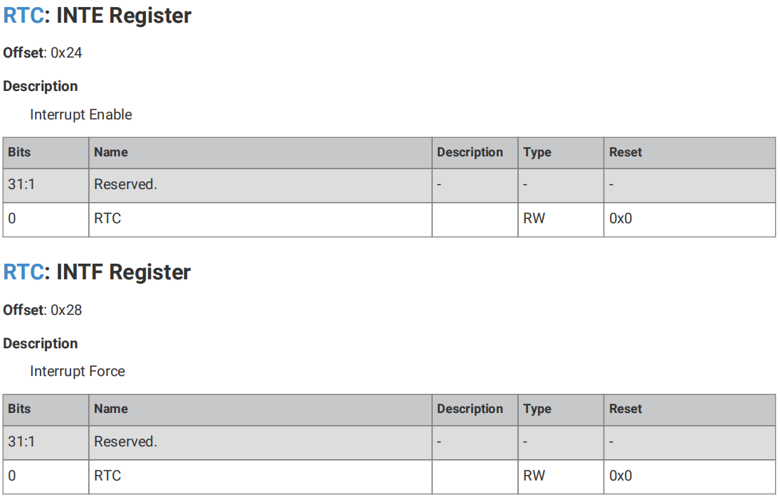
When interrupt‑match conditions are met, the RTC asserts an interrupt signal to the processor. It can also wake the ROSC (Ring Oscillator) and XOSC (Crystal Oscillator) out of sleep modes. Overall the RTC interrupt system is flexible and powerful. Developers can selectively enable field‑based interrupts to implement scheduled tasks and alarms. RTC interrupts can also wake‑up the processor and oscillators to reduce system power consumption.
- RTC wake‑up functionality
While the device stays in low‑power modes, the RTC peripheral keeps running and can trigger an interrupt upon reaching a pre‑configured timestamp to wake the system.
Raspberry Pi Pico in Sleep Mode In this mode the processor enters sleep state, and unused chip clocks are stopped. The chip may be configured so only clk_rtc (the slow RTC reference clock) and minimal wake‑up logic remain active. The processor is woken from sleep mode upon an RTC alarm interrupt.
Raspberry Pi Pico in Dormant Mode In this mode all chip clocks are halted. These steps must be completed to wake‑up from dormant mode: RTC must be configured to use an external reference clock supplied via GPIO pins. Configure the RTC to run off that external reference clock. If the processor is running from PLL clocks, switch it over to XOSC or ROSC (external / internal oscillator). Power‑down all PLLs. Configure the RTC with desired wake‑up time (one‑shot or periodic wake‑up). (Optional) Power‑down most memory regions. Enter DORMANT mode.