RP2040 PIO Driving WS2812 LED Strip: From Principles to MicroPython Implementation
Two approaches to drive WS2812 on Pico: built‑in NeoPixel library and hardware‑timing PIO implementation for GRB‑encoded color‑chasing light effects.
COMPONENTS
PROJECT DESCRIPTION
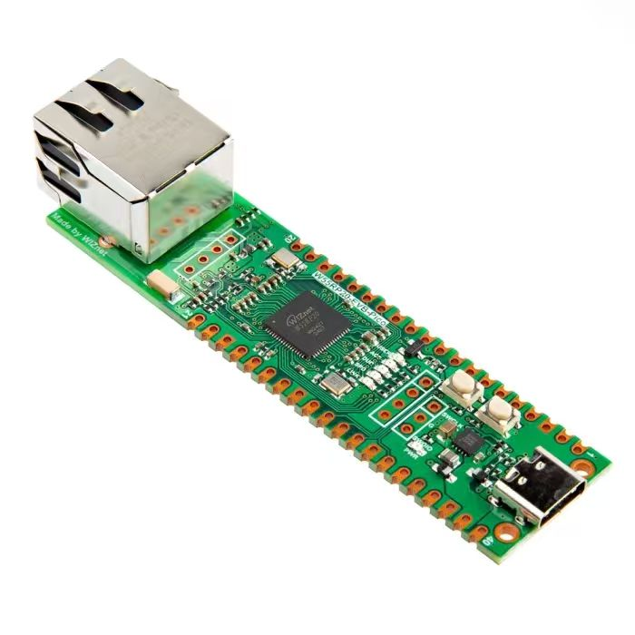
【Preliminary Note】The original hardware example in this article was written based on the RP2040. The actual hardware used in this hands-on demonstration features the W55RP20 as the main controller chip. The circuit logic and UF2 flashing operation principles are universally applicable, with only the main controller model differing. The original chip model mentioned in the circuit descriptions below is provided for reference purposes only.
WS2182 Color Light Controlled by PIO
1. Introduction to WS2812 LED
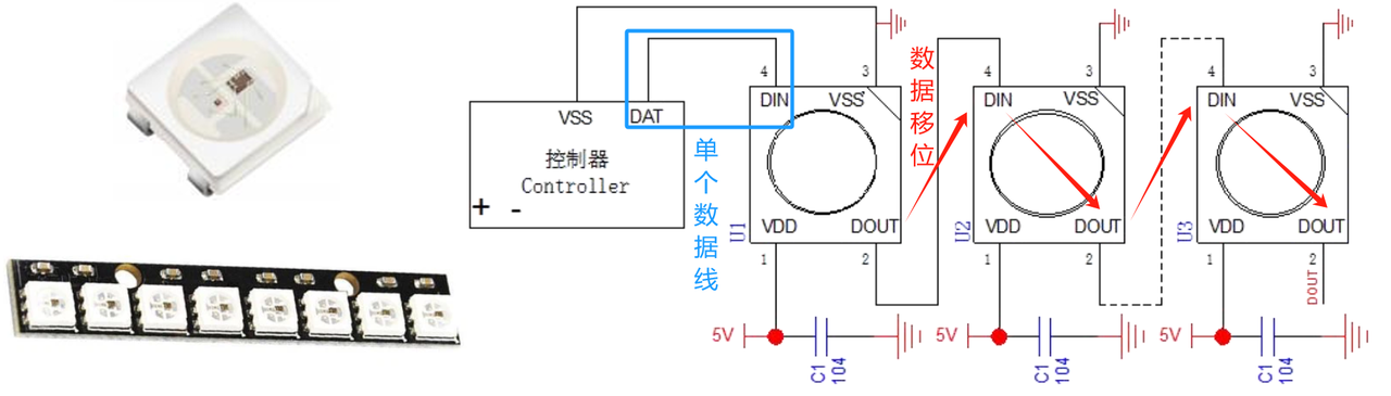
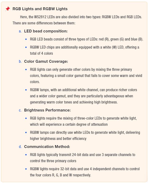
WS2812 LED is a type of Neopixel individually addressable RGB LED, and we can control multiple WS2812 RGB full-color LEDs via a single data line. The working principle of WS2812 is to transmit 24-bit RGB color data to each LED bead one by one through a single data line. Each WS2812 chip contains a shift register for receiving and forwarding data. After a complete frame of RGB data is received, the corresponding LED bead will display the matching color.By connecting multiple WS2812 lamp beads in series, flexible and programmable LED strips, LED matrices and other devices can be formed. Common applications include decorative lighting, LED displays, smart lamps and the like.
The main features of the WS2812 include:
High integration: A single WS2812 LED integrates RGB tri-color LEDs and a control chip inside, and can be controlled with only a single data line
Series Control: Multiple WS2812 LEDs can be used in series to form an LED strip or an LED array
Programmable Control: By controlling data signals via programming, independent dimming and color control for each LED can be achieved
Low power consumption: The operating voltage is 5V, and the power consumption of a single LED is only 60mW
High Brightness: The LED delivers high luminous brightness, with a maximum brightness ranging from 6500 to 8000 mcd
Compact size: The package measures only 5.0mm x 5.0mm x 1.6mm
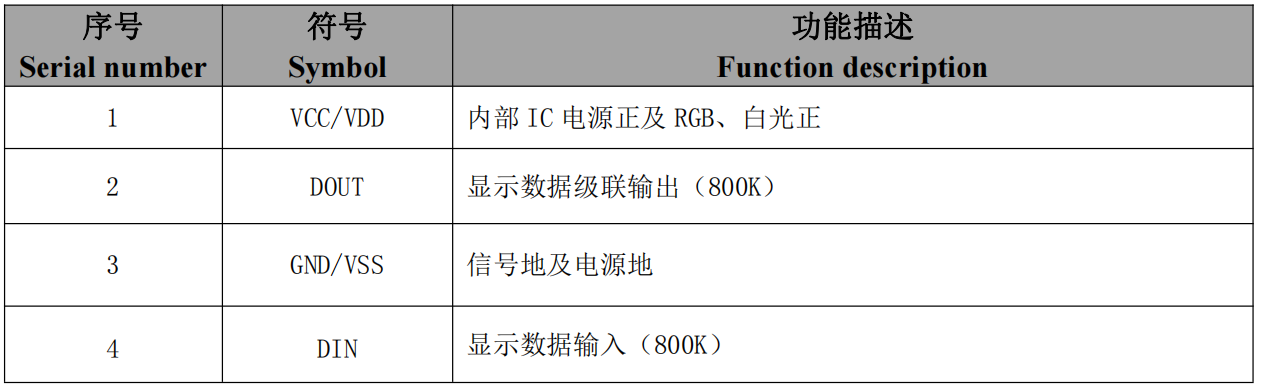
The WS2812 has four pins, and their functions are as follows:
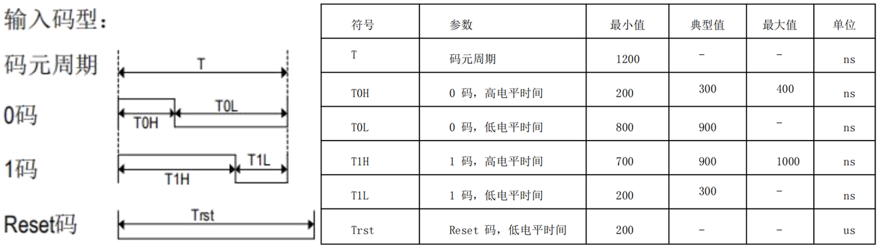
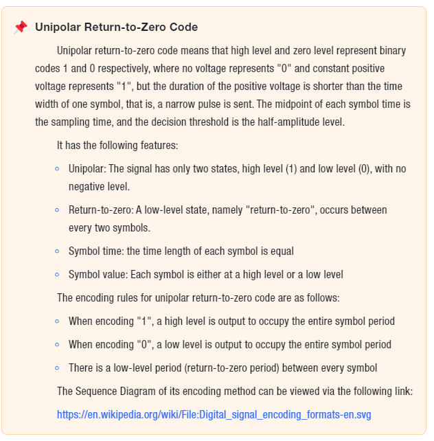
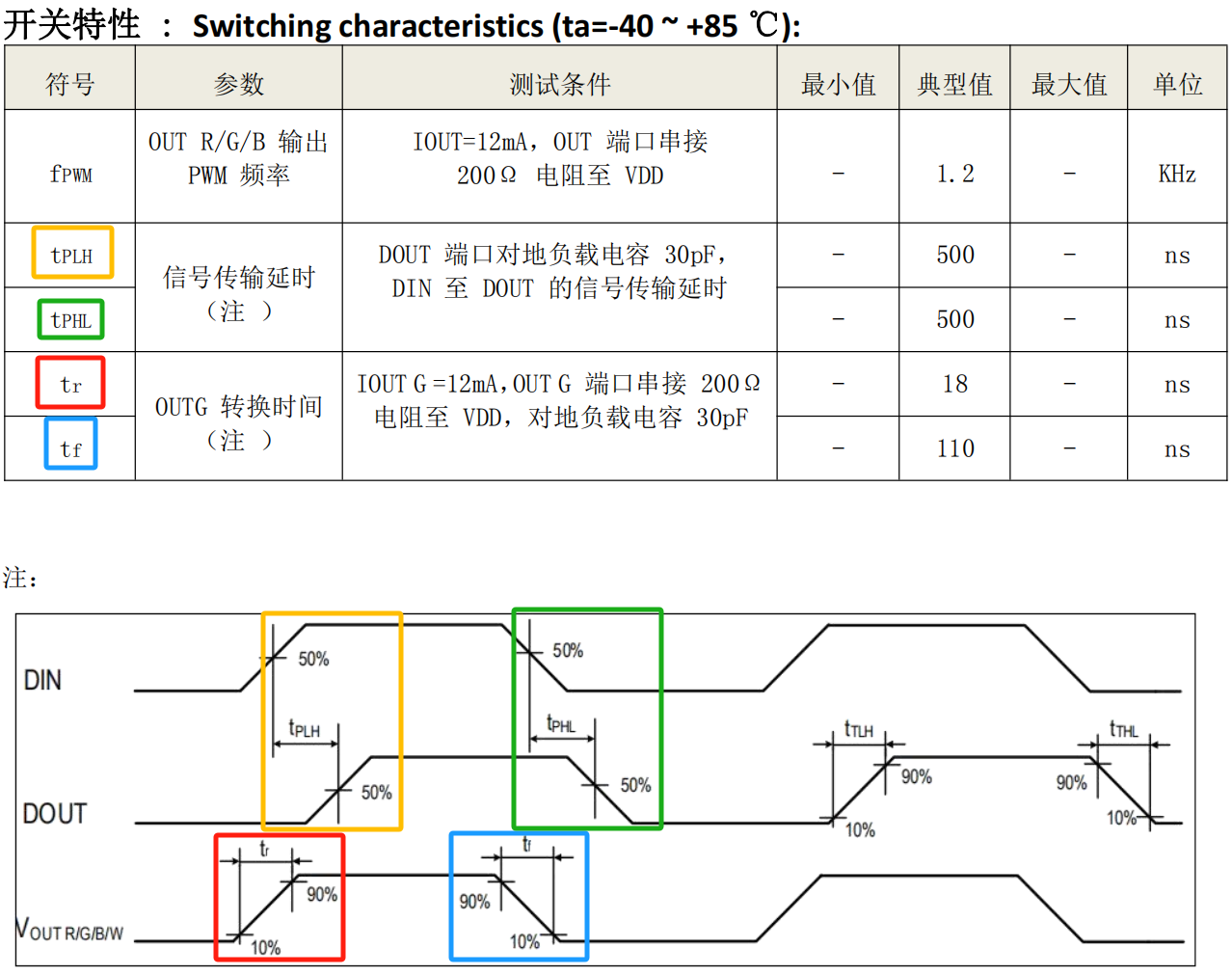
It adopts the communication mode of unipolar return-to-zero code, and each symbol must have a low level:
After the chip is powered on and reset, the DIN pin receives the data transmitted from the controller:
First, the incoming 24-bit data is extracted by the first chip and then sent to the data latch inside the chip.
The data latch inside the chip generates control signals with different duty cycles at the OUTR, OUTG, and OUTB control terminals based on the received 24-bit data, so as to make the LED produce different colors.
The remaining data, after being shaped and amplified by the internal shaping processing circuit, starts to be forwarded and input to the next cascaded chip via the DO port; the signal decreases by 24 bits after transmission through each chip.
When the chip does not receive the RESET signal input from the DIN terminal, the output of the OUTR, OUTG and OUTB pins remains unchanged; when the RESET signal is received, each control terminal will change its output according to the received data.
The chip adopts automatic shaping and forwarding technology, so that the cascade number of this chip is not limited by signal transmission, but only restricted by the requirements of signal transmission speed.
Its Communication Protocol is: reset signal + 24-bit data of the first chip + 24-bit data of the second chip +. .. + 24-bit data of the Nth chip. Data is transmitted with the most significant bit first and in GRB order (the color order varies among different WS2812 chips, which shall be subject to the datasheet):
Among them, bits R0-R7 control the red light color output, bits G0-G7 control the green light color output, and bits B0-B7 control the blue light color output. Since each LED bead needs to store 24-bit RGB color data, when the light strip is long and the number of LED beads is large, the video memory data will occupy a large amount of RAM space.
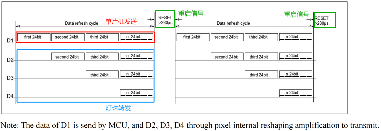
Wherein D1 is the data sent by the MCU terminal, and D2, D3, D4 are the data automatically shaped and forwarded by the cascade circuit. The controller can continuously send 24-bit RGB control signals: after the first LED bead intercepts the first 24 bits of data, it displays the data on its own LED, shapes the remaining data and then sends it to the second LED bead. The second LED bead will intercept the second set of 24-bit data for display, and continue to forward the remaining data until the last set of data is displayed.
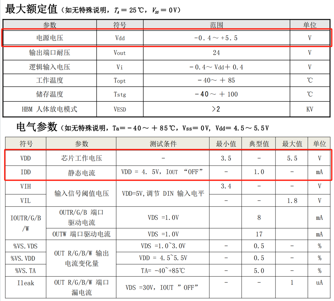
The electrical parameters of WS2812 are as follows:
2. Drive WS2812 LEDs using the NeoPixel class
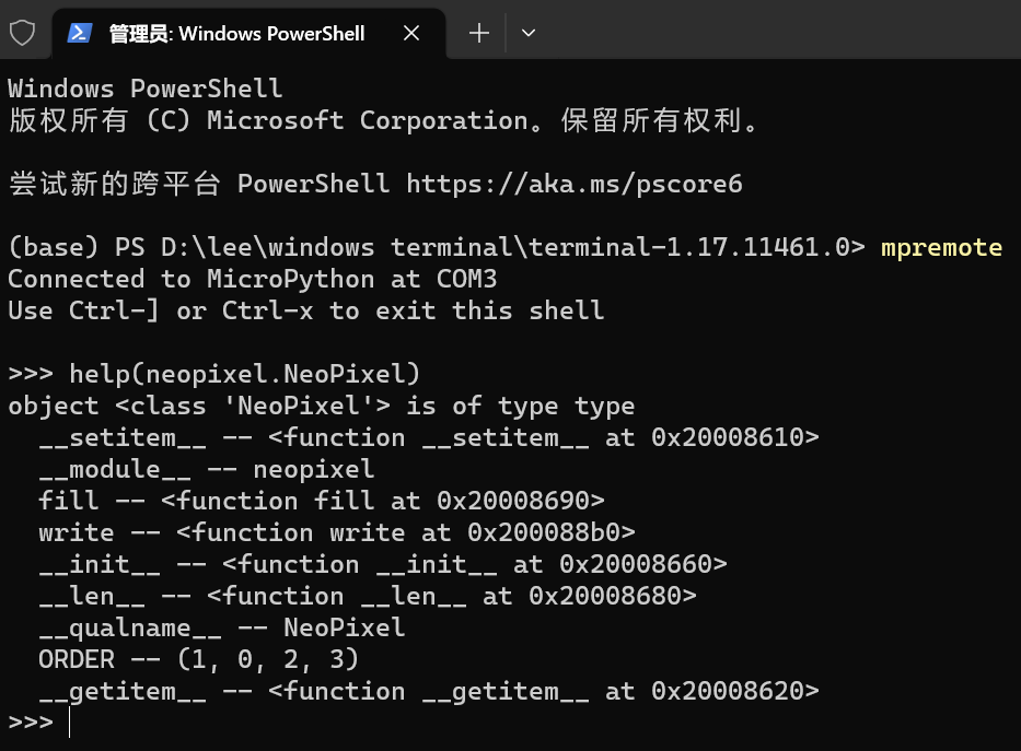
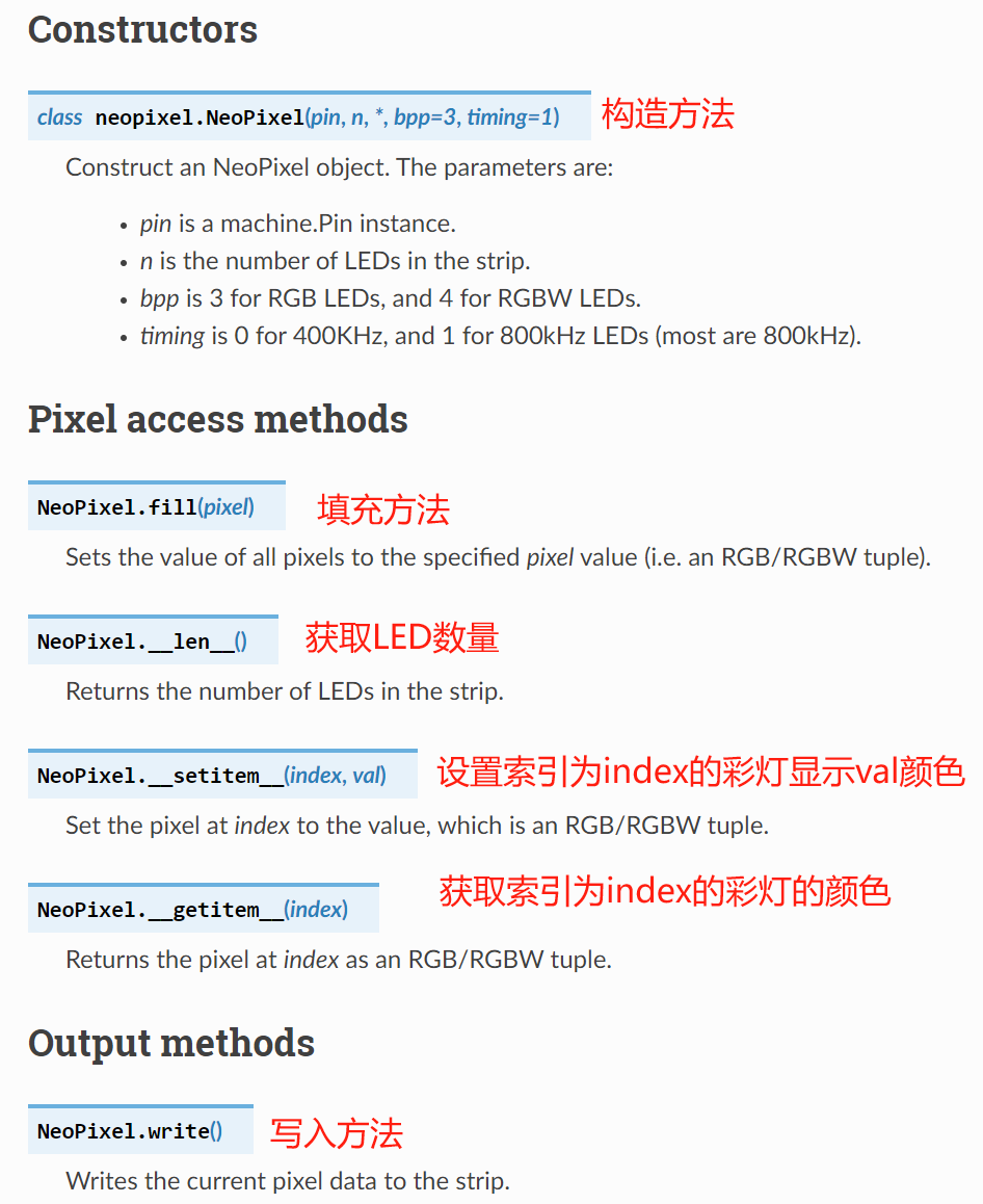
We can use the built-in neopixel module in the MicroPython library, and the NeoPixel class within it to drive WS2812 LED lights:
It provides the following methods to control WS2812 LED lights:
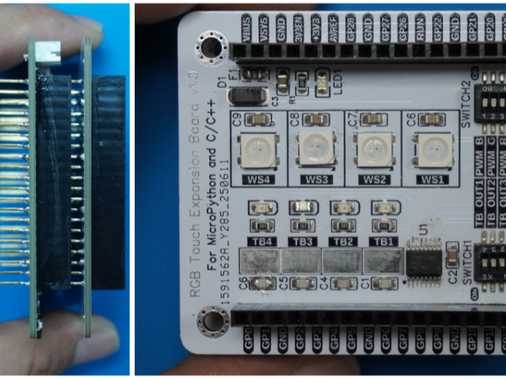
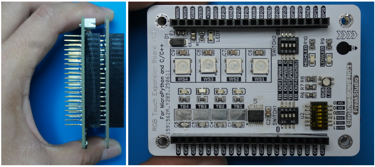
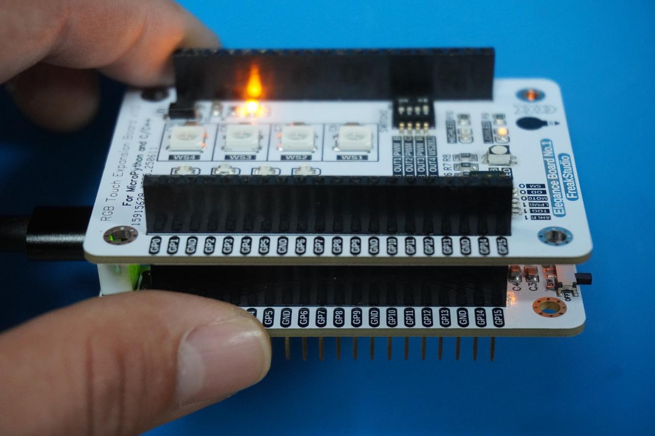
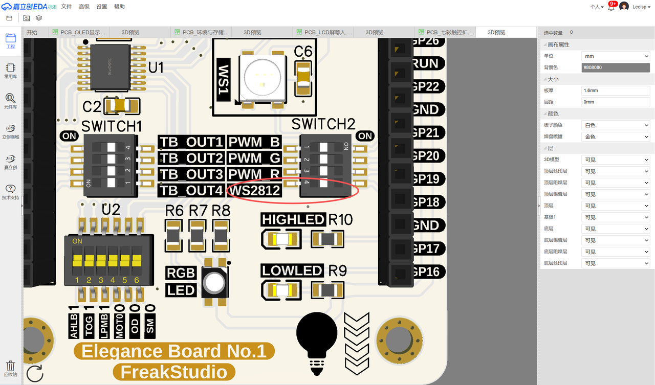
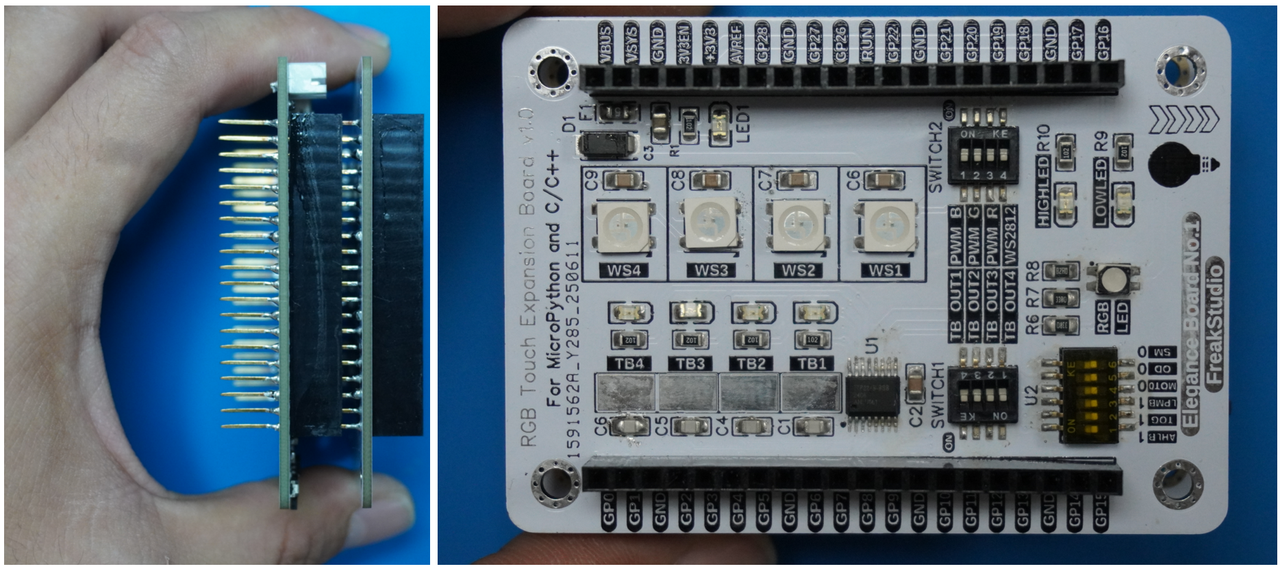
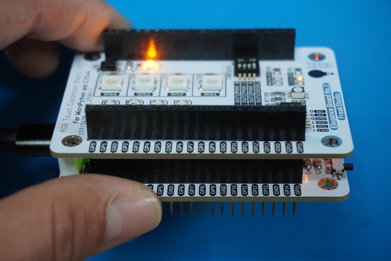
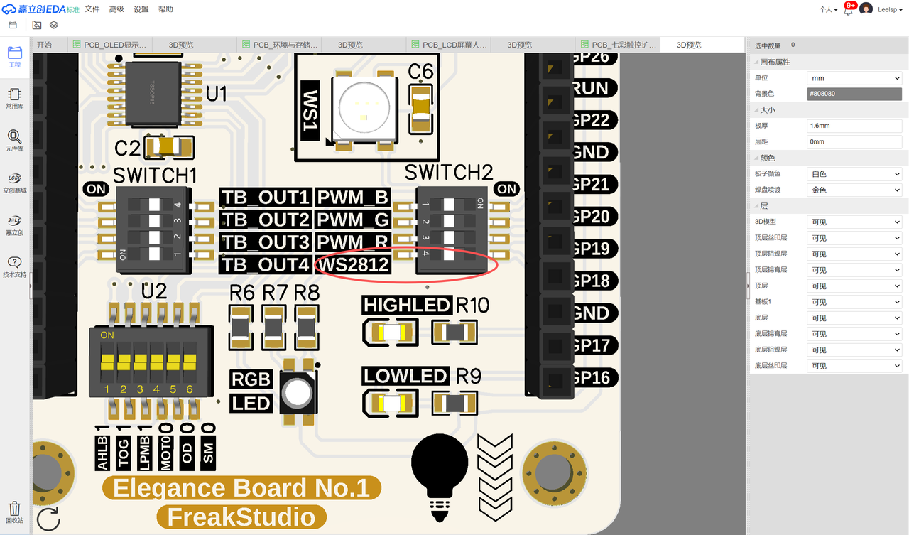
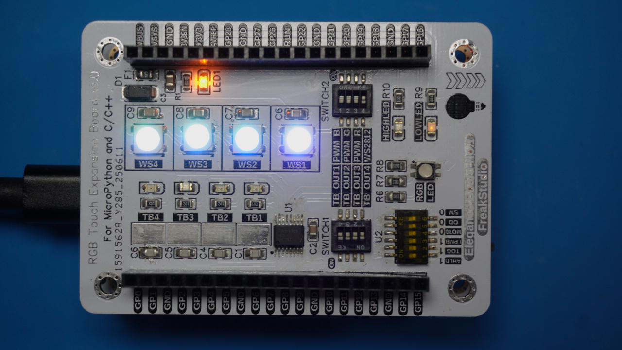
In the following experiment, we need to insert the Fengya No. 1 Board - Colorful Touch Expansion Board into the Fengya No. 1 Board - Universal Compatible Expansion Board, and meanwhile turn on the SWITCH2 DIP switch's WS2812 option:
In the following code, we use 4 WS2812 LEDs in a single row WS2812 to implement a chasing light. We use the GP18 pin of the Raspberry Pi Pico as the signal line for the WS2812, and power the WS2812 LEDs with 5V. The following code can be found in the elegance-devkit v1\Demo\32 NeoPixel folder in the resource package we provided.
Its basic working principle is: the lighting function is called periodically, and in the lighting function, all LED lamps are traversed, the currently selected lamp is set to red, and the other lamps are set to blue. Then, it updates the NeoPixel strip to display the new colors. After each lamp has been polled to display red once, all of them turn green, and then the cycle repeats.
The sample code is as follows:
# Python env   : MicroPython v1.23.0
# -*- coding: utf-8 -*-
# @Time    : 2024/7/27 下午2:55
# @Author  : 李清水
# @File    : main.py
# @Description : 通过GPIO控制NeoPixel灯带闪烁

# ======================================== 导入相关模块 ========================================

# 导入硬件相关的模块
from machine import Pin, Timer
# 导入时间相关的模块
import time
# 导入NeoPixel相关的模块
from neopixel import NeoPixel
# 导入随机数模块
import random

# ======================================== 全局变量 ============================================

# 定义 NeoPixel 连接的 GPIO 引脚为 18
NEOPIXEL_PIN = 18
# 定义 NeoPixel 灯带上 LED 的数量为 4 个
NUMBER_PIXELS = 4
# 定义一个计数器变量,用于控制 LED 的移动
counter = 0

# ======================================== 功能函数 ============================================

def move_pixel(timer: Timer) -> None:
    """
    移动 NeoPixel 灯带上的 LED。

    Args:
        timer (machine.Timer): 定时器实例。

    Returns:
        None

    Description:
        该函数通过定时器周期性调用,控制 NeoPixel 灯带上的 LED 移动。
        当前 LED 显示红色,其他 LED 显示蓝色,当计数器超过 LED 数量时,所有 LED 显示绿色并重置计数器。
    """
    # 声明 counter 变量为全局变量,以便在函数内部修改它
    global counter

    # 遍历所有 NeoPixel LED
    for i in range(0, NUMBER_PIXELS):
        # 如果当前 LED 的索引等于 counter 值,则设置为红色 (10,0,0)
        if i == counter:
            strip[i] = (55,0,0)
        # 否则,设置为蓝色 (0,0,10)
        else:
            strip[i] = (0,0,55)
        # 将更新后的颜色写入 NeoPixel 灯带
        strip.write()

    # 递增 counter 变量,用于控制下一个 LED 的移动
    counter += 1

    # 如果 counter 大于 LED 的数量
    if counter > NUMBER_PIXELS:
        # 设置所有 LED 为绿色 (0,10,0)
        strip.fill((0,55,0))
        strip.write()
        # 将 counter 重置为 0
        counter = 0

def random_color_flow(timer: Timer) -> None:
    """
    实现随机颜色流水灯效果。

    Args:
        timer (machine.Timer): 定时器实例。

    Returns:
        None

    Description:
        该函数通过定时器周期性调用,控制 NeoPixel 灯带上的 LED 显示随机颜色。
        每次调用时,所有 LED 的颜色都会更新为随机颜色。
    """
    # 声明 counter 变量为全局变量,以便在函数内部修改它
    global counter

    # 遍历所有 NeoPixel LED
    for i in range(NUMBER_PIXELS):
        # 为每个 LED 设置随机颜色 (R, G, B)
        strip[i] = (random.randint(0, 55), random.randint(0, 55), random.randint(0, 55))

    # 将更新后的颜色写入 NeoPixel 灯带
    strip.write()

# ======================================== 自定义类 ============================================

# ======================================== 初始化配置 ==========================================

# 上电延时3s
time.sleep(3)
# 打印调试信息
print("FreakStudio: Using NeoPixel to control WS2812 LED")

# 创建一个 NeoPixel 对象,连接到 GPIO 引脚 18,并设置 LED 的数量为 4 个
strip = NeoPixel(Pin(NEOPIXEL_PIN), NUMBER_PIXELS)
# 创建一个软件定时器对象
timer = Timer(-1)

# ========================================  主程序  ===========================================

# 初始化定时器,每 200 毫秒触发一次 move_pixel 函数
timer.init(period=200, mode=Timer.PERIODIC, callback=random_color_flow)

while True:
    # 打印当前的 counter 值
    print('timer counter :', counter)
    # 延时 5 秒
    time.sleep(5)
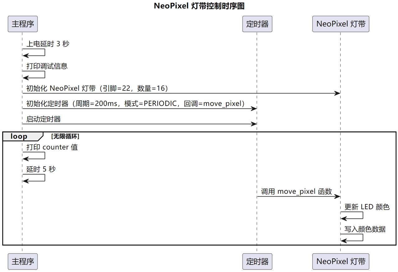
Its workflow is shown in the following figure:
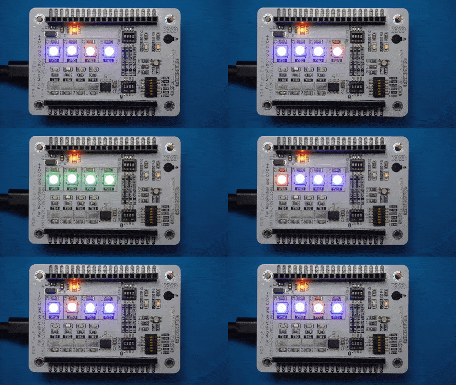
Burn the code into the Pico and connect to the remote terminal, you will see that the WS2812 chasing LED strip is implemented as follows:
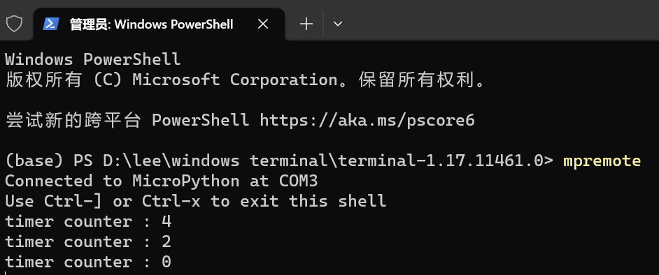
And the terminal outputs the count value periodically:
We can also modify the timer callback random_color_flow () function to implement arbitrary flowing light effects:
The basic principle is to use the random library built into MicroPython, the randint function to generate a random RGB color array. After burning the code, the effect is shown in the following figure:
3. Driving WS2812 LEDs with PIO
Using PIO to control WS2812 color lights, compared with using the built-in neopixel module to control WS2812 color lights, has the advantage of high real-time performance: PIO is a dedicated hardware peripheral that can run independently of the CPU, perform specific data transmission tasks, and generate precise timing signals without CPU involvement, thus greatly reducing the CPU load. This hardware acceleration method can achieve higher transmission efficiency and lower power consumption.
In the following experiment, we need to insert the Fengya No. 1 Board - Colorful Touch Expansion Board into the Fengya No. 1 Board - Universal Compatible Expansion Board, and at the same time turn on the SWITCH2 DIP switch WS2812 option:
The following code can be found in the material package we provided, under the elegance-devkit v1\Demo\33 PIO_NeoPixel folder.
Next, let's take a look at how to use PIO finite-state machine to control NeoPixel to implement a colorful chasing LED, the sample code is as follows:
# Python env   : MicroPython v1.23.0
# -*- coding: utf-8 -*-
# @Time    : 2024/7/27 下午9:52
# @Author  : 李清水
# @File    : main.py
# @Description : 通过PIO控制NeoPixel灯带闪烁

# ======================================== 导入相关模块 ========================================

# 导入硬件相关的模块
from machine import Pin
# 导入时间相关的模块
import time
# 导入RP2040相关的模块
import rp2

# ======================================== 全局变量 ============================================

# LED灯带的颜色列表
colors = [
    (128, 0, 0),    # LED 1,红色,亮度降低
    (128, 82, 0),   # LED 2,橙色,亮度降低
    (128, 128, 0),  # LED 3,黄色,亮度降低
    (0, 128, 0),    # LED 4,绿色,亮度降低
    (0, 128, 128),  # LED 5,青色,亮度降低
    (0, 0, 128),    # LED 6,蓝色,亮度降低
    (38, 0, 65),    # LED 7,紫色,亮度降低
    (119, 65, 119), # LED 8,紫罗兰色,亮度降低
    (128, 53, 90),  # LED 9,热粉色,亮度降低
    (128, 10, 74),  # LED 10,深粉色,亮度降低
    (128, 128, 128),# LED 11,白色,亮度降低
    (96, 96, 96),   # LED 12,银色,亮度降低
    (0, 0, 0),      # LED 13,黑色
    (64, 64, 64),   # LED 14,灰色,亮度降低
    (128, 0, 128),  # LED 15,品红色,亮度降低
    (128, 128, 128) # LED 16,白色,亮度降低
]

# ======================================== 功能函数 ============================================

# 定义一个 asm_pio 函数,用于生成 PIO 程序
# 指定了 side-set 引脚的初始状态为低电平
# 指定了输出数据的移位方向为左移
# 使能autopull数据自动加载,自动加载阈值为24 位数据
@rp2.asm_pio(sideset_init=rp2.PIO.OUT_LOW,
             out_shiftdir=rp2.PIO.SHIFT_LEFT,
             autopull=True, pull_thresh=24)
def ws2812() -> None:
    """
    定义 WS2812 LED 驱动的 PIO 程序。

    Args:
        None

    Returns:
        None

    Description:
        该 PIO 程序用于驱动 WS2812 LED 灯带,通过状态机控制 LED 的颜色数据输出。
        程序通过 side-set 引脚输出高低电平信号,控制 LED 的亮灭。
    """
    # 标记程序的起始位置,当程序执行到 wrap() 时,会跳转回此处继续执行
    wrap_target()
    # 定义一个名为 bitloop 的标签,用于循环处理每个 LED 灯的数据
    label('bitloop')
    # 将寄存器 osr 中的 1 位数据输出到x寄存器,首先执行侧集操作设置侧集引脚为低电平 2 个周期
    out(x, 1).side(0)[2]
    # jmp 会判断 X 暂存器的值是不是 0,如果是0则跳转到 do_zero 标签
    # jmp 的 delay 会在做完条件判断后执行,所以总共会花 2 + 1 cycles
    jmp(not_x, 'do_zero').side(1)[2]
    # 如果 X 的值是 1,pioasm 会执行第三行
    # 这一行没有改变 side-set 的电位,所以继续维持高电位(3 + 1 cycles),并跳回 bitloop 标签
    jmp('bitloop')[3]
    # 定义一个名为 do_zero 的标签,用于处理 0 值的位
    label('do_zero')
    # 若 X 的值是 0,则会执行 nop(),并将 side-set 设为低电位,时间也是 3 + 1 cycles
    nop().side(0)[3]
    # 程序执行完毕后跳转回 wrap_target() 处继续执行
    wrap()

# ======================================== 自定义类 ============================================

# ======================================== 初始化配置 ==========================================

# 上电延时3s
time.sleep(3)
# 打印调试信息
print("FreakStudio: Using PIO to control WS2812 LED")

# 初始化一个状态机对象,并将 ws2812 函数加载到状态机
# WS2812 的通信频率是 800 kHz,将其乘以10可得8 MHz (即一个WS2812时钟周期 = 10个PIO执行时钟周期)
sm = rp2.StateMachine(0, ws2812, freq=8000000, sideset_base=Pin(18))

# ========================================  主程序  ===========================================

# 启动状态机
sm.active(1)

while True:
    # 依次输出每个LED灯的颜色数据
    for r, g, b in colors:
        # 把红、绿、蓝三个值分别左移8位、16位、24位,然后相加转成一个 24-bit GRB值
        value = (g << 16) | (r << 8) | b
        # sm.put() 方法实际上会写入一个 32-bit 的数据到 FIFO
        # 写入 FIFO 时左移8位
        sm.put(value, 8)

    # 列表左移
    colors = colors[1:] + [colors[0]]

    # 延时200ms
    time.sleep_ms(200)
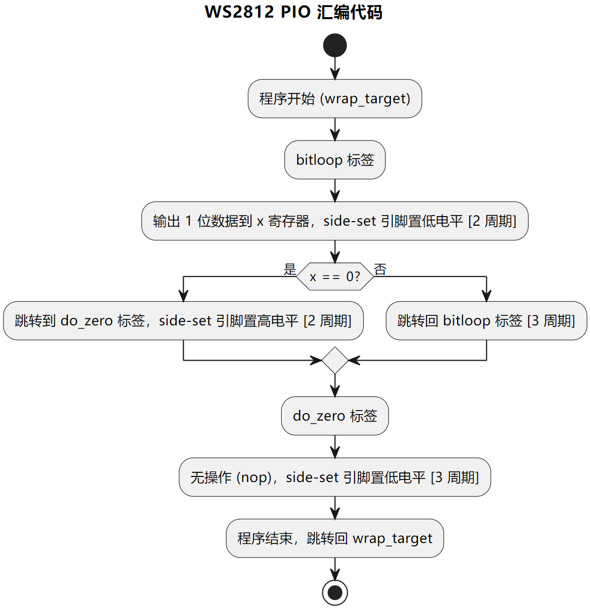
Simply put, the workflow of the aforementioned PIO program is as follows:
For each LED lamp, the program outputs 24-bit RGB data, with 8 bits for each color
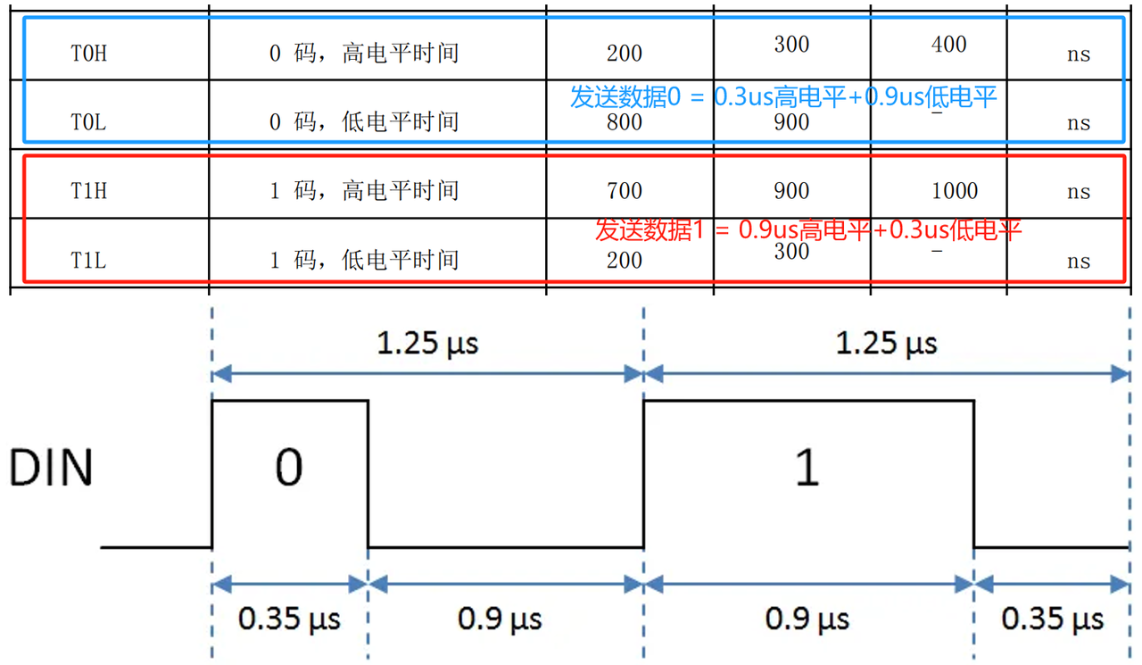
For each bit, if the value is 0, output a high level of 0.3 μs followed by a low level of 0.9 μs; if the value is 1, output a high level of 0.9 μs followed by a low level of 0.3 μs
Then, we only need to write the corresponding GBR value of each LED to the finite-state machine to realize the display of different colors of the WS2812 LEDs.
Next, we will explain the principle of the driver code in detail.
As we mentioned earlier, WS2812 adopts unipolar return-to-zero code for communication, where data 1 and data 0 are distinguished by the duration of the high level:
Need to redraw the diagram!
WS2812 has a communication frequency of 800 kHz, which multiplied by 10 gives 8 MHz (i. e., one WS2812 clock cycle = 10 PIO execution clock cycles), and the output binary data can be controlled by adjusting the high and low level output of each PIO execution clock cycle:
First, output a high level for 3 PIO execution cycles on DIN (denoted as T1 = 0.375 us here)
Adjust the high and low levels output on DIN according to the data bits to be transmitted (1 = high level, 0 = low level),
and maintain the level for 4 PIO execution cycles (here denoted as T2 = 0.5 us)
Finally pull low DIN the level on for 3 PIO execution cycles (T3 = 0.375 us)
For convenience, we refer to these three stages as T1, T2 and T3, with a ratio of 3:4:3.
    T1    T2    T3
  └─────┴─────┴─────┘ = 1.25 us
    3  :  4  :  3       T1+T2 或 T2+T3 = 0.875 us
1 = 高    高    低
0 = 高    低    低
In the PIO program section, we have first used the @rp2. asm_pio decorator to enable autopull for automatic data loading, with the autopull threshold set to 24 bits. When the data in the OSR reaches 24 bits, the OUT instruction will be automatically executed to load data from the TX FIFO for corresponding operations; we only need to OUT the data we intend to send.
During the above data transmission phase, a total of 7 clock cycles are consumed to complete the T1 and T2 phases.
Now, the PIO program returns to the start, uses the OUT instruction to fetch a piece of data, and sets the side-set pins to low level; its execution time (2 + 1 PIO execution cycles) will then become the T3 phase of the previous LED. Even after the last bit of GBR data for the final LED has been written and there is no remaining data in the OSR, the delay of the OUT instruction will continue to complete the T3 phase of the last data.
The overall Sequence Diagram is shown as follows:
When transmitting the GBR data of the LED lamp, we used the following statement:
# 依次输出每个LED灯的颜色数据
for r, g, b in colors:
    # 把红、绿、蓝三个值分别左移8位、16位、24位,然后相加转成一个 24-bit GRB值
    value = (g << 16) | (r << 8) | b
    # sm.put() 方法实际上会写入一个 32-bit 的数据到 FIFO
    # 写入 FIFO 时左移8位
    sm.put(value, 8)
Here, we shift the three values of red, green and blue left by 8 bits, 16 bits and 24 bits respectively, then add them up to convert into a 24-bit GRB value. It should be noted that when WS2812 reads data, the MSB comes first and the LSB comes after, and the OSR shift register is 32 bits in size. To enable WS2812 to read data starting from the MSB, we need to shift the GRB value left by 8 bits. For the missing lower 8 bits of data, the PIO state machine will suspend execution and wait for the arrival of the next 32-bit data.Here, when enabling the autopull function for automatic data loading, we set the auto-loading threshold to 24-bit data. Therefore, each time the OUT module finishes processing the 24-bit GRB data corresponding to one LED, it will automatically load the 24-bit GRB data for the next LED from the TX FIFO (note that the actual loading size of the OUT module is 32 bits, with the lower 8 bits being invalid).
In the main loop, we use the following statement to perform a cyclic left shift on the color list (each iteration shifts all elements in the list one position to the left cyclically), so as to achieve the effect of the WS2812 colorful chasing LED light (visually, the corresponding color of each LED keeps shifting to the left):
colors = colors[1:] + [colors[0]]
Wherein:
colors[1:]: This syntax is used to get all elements from the second element to the last element in the list colors. In other words, this operation will return a new list containing all elements except the first one.
[colors[0]]: This syntax creates a new list that contains only the first element of the colors list
colors[1:] + [colors[0]]: This operation concatenates the two lists mentioned above to generate a new list, where the first element is the second element of the original list, and the last element is the first element of the original list.
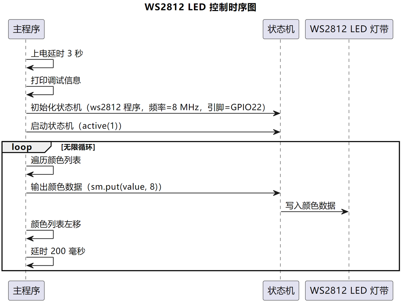
This left shift operation can be used to implement the cyclic color change effect of the LED strip. Each time this line of code is executed, the elements in the color list will shift one position to the left, thus displaying different color combinations. The overall flow of the above program is shown in the following figure:
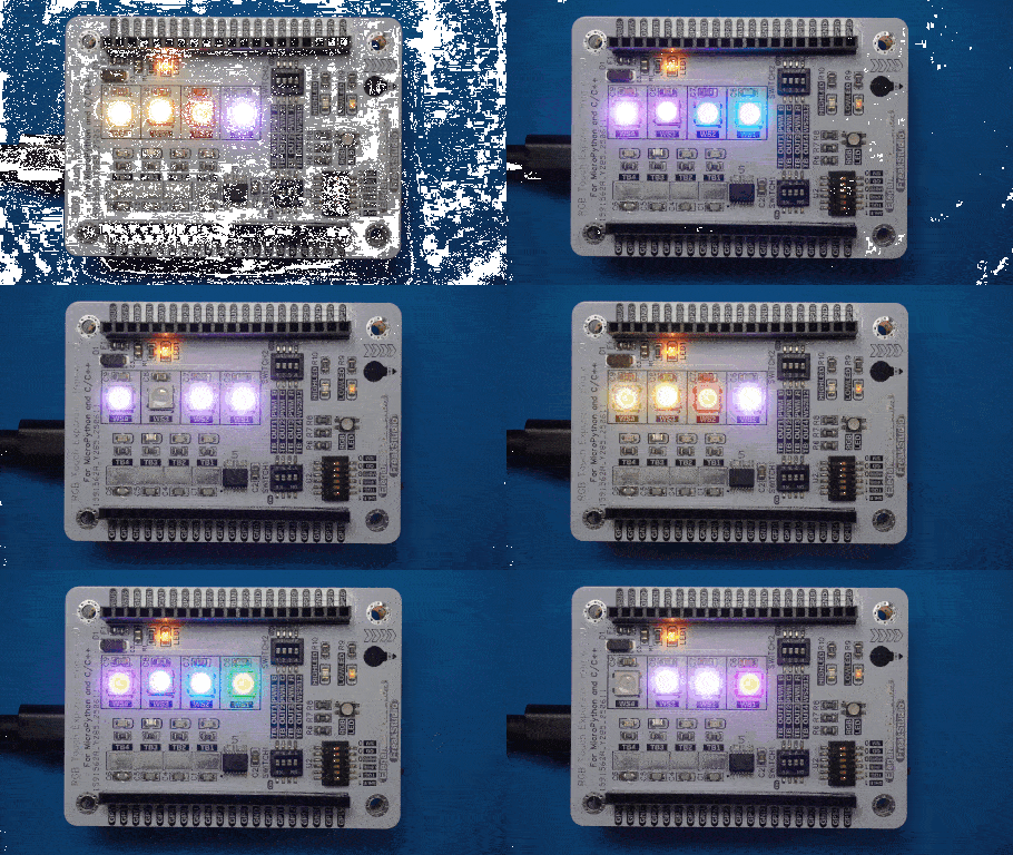
Burn the code into the Pico, and you will see that the WS2812 LED strip achieves the effect of cyclic color changes of the LEDs: