



RP2040 Built‑in WDT Deep‑Dive: Clock, Counter & Register Analysis for Pico
RP2040 built‑in watchdog mechanism, clock, counter and key registers.
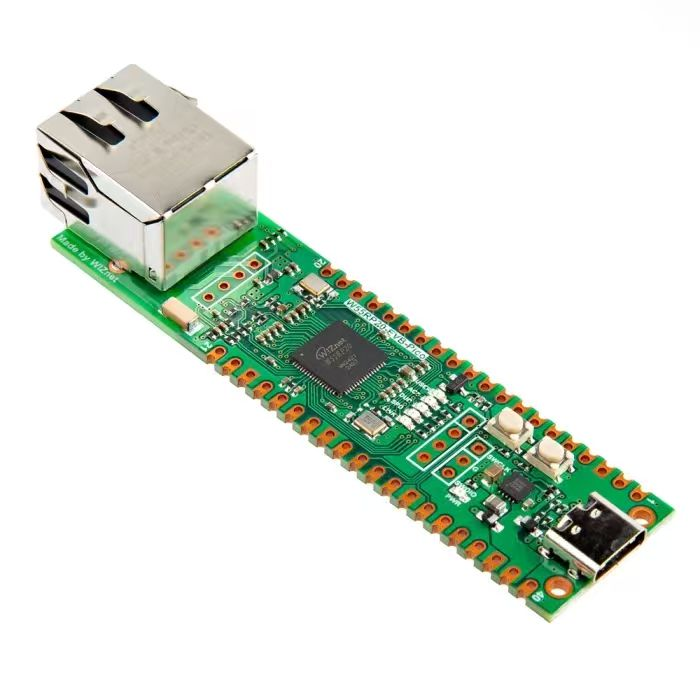
The RP2040 chip on‑board Raspberry Pi Pico integrates a hardware watchdog timer (WDT) peripheral:
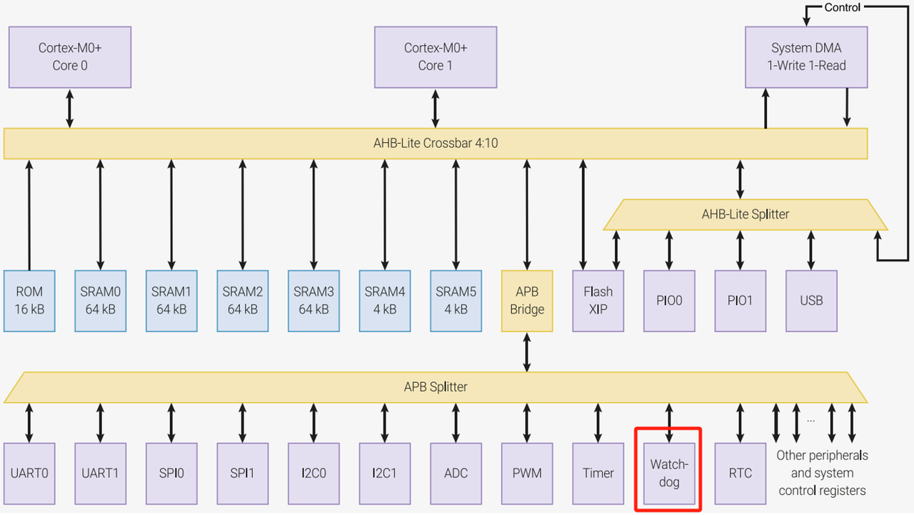
The on‑board watchdog peripheral of Raspberry Pi Pico is attached to the APB bus.
The watchdog timer inside RP2040 features a 24‑bit counter with maximum value 0xFFFFFF (equal to 16 777 215).
- Watchdog clock input
Inside the RP2040 microcontroller, the reference clock clk_tick used by watchdog timer(WDT) is driven by clk_ref:
Ideally, clk_ref is configured to use the crystal oscillator.
clk_ref is internally divided to generate watchdog clock clk_tick, which provides timing source for watchdog timer operation.

The period of clk_tick is typically 1 microsecond (μs). This means the watchdog timer counts in 1‑microsecond intervals for precise system‑health monitoring.
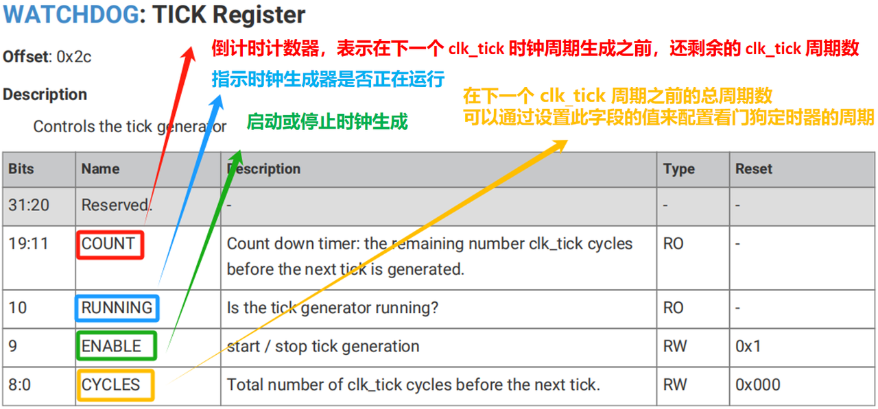
Clock division ratio and watchdog timer interval can be adjusted by configuring the TICK register:
- Watchdog timer reset
The watchdog timer is reset by the rst_n_run signal. When digital‑core power supply(DVDD) is stable and the RUN pin is high, the rst_n_run signal is asserted and the watchdog timer performs reset.
rst_n_run is a reset signal closely related to chip power‑management and reset‑control logic. As previously introduced for Raspberry Pi Pico, the power‑on state machine of RP2040 de‑asserts resets for internal hardware modules in a defined sequence. This ensures every module initializes in correct order and avoids conflicts or errors during reset.
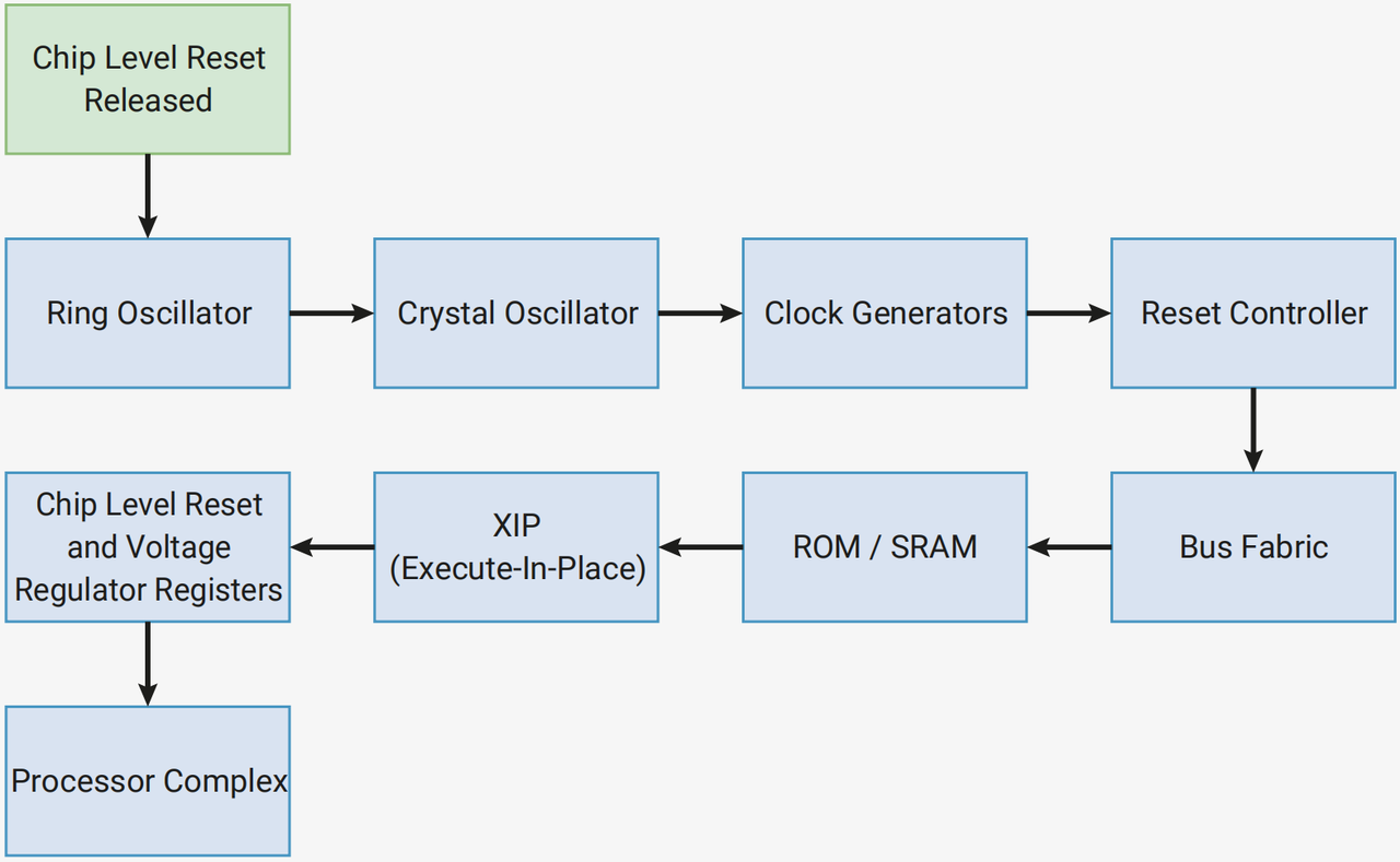
Power‑on state‑machine reset‑sequence table.
Each module reset is controlled by internal rst_n signal. After completing reset, each module outputs a high‑level rst_done signal indicating reset completion. The power‑on state‑machine waits for rst_done from each module before proceeding to the next module. After the power‑on state‑machine finishes resetting all modules, the rst_n_run signal is used to exit specific reset states. This signal applies to modules that need initialization at startup but must NOT be reset during power‑on state‑machine execution. Examples include ring‑oscillator and crystal‑oscillator internal logic, continuously‑running clock dividers and the watchdog timer.
- Watchdog counter
Counter operations for RP2040 watchdog timer involve the LOAD register and TIME bit‑field inside the CTRL register:
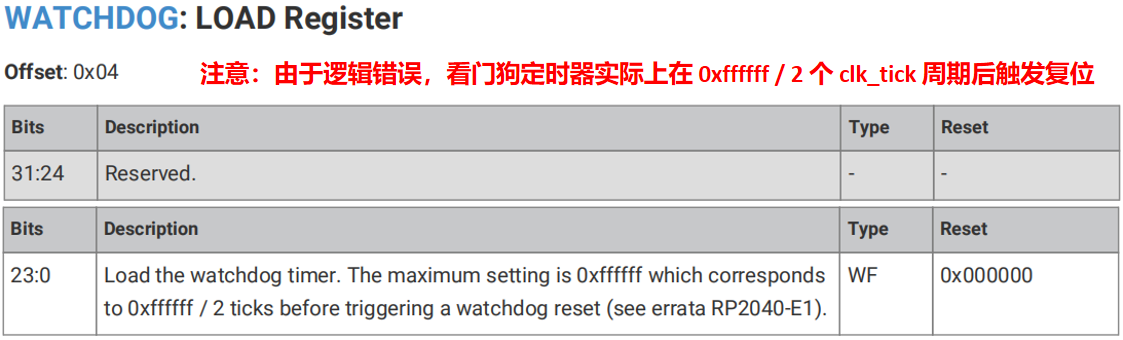
The LOAD register sets the initial value for watchdog counter:
CTRL.TIME bit‑field reflects current watchdog‑counter value:
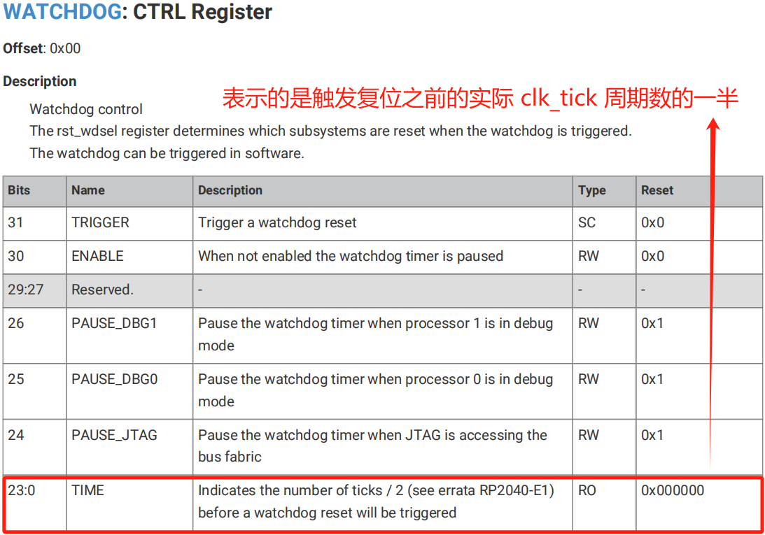
Note: due to an errata (RP2040‑E1 silicon bug), the watchdog counter decrements twice per single clk_tick cycle. Actual countdown duration equals half of expected value. When LOAD register is set to 0xffffff (16 777 215), watchdog triggers reset after 0xffffff / 2 clk_tick cycles.
Given typical clk_tick = 1 μs: 16777215 / (2 * 1000000) s = 8.388 s = 8388 ms
Practical watchdog timeout range is approximately from 1 μs up to 500 ms.
Bits PAUSE_DBG1, PAUSE_DBG0 and PAUSE_JTAG inside CTRL register can pause watchdog timer when core0 / core1 enter debug mode or JTAG debug interface accesses the bus. This prevents watchdog timeout from interfering with debugging workflows.
The REASON register can be read to obtain cause of the previous reset:
It tells whether last reset was watchdog forced‑reset, watchdog timeout reset or hardware reset:
When both FORCE bit and TIMER bit are 0: last reset originates from hardware reset.
When FORCE bit equals 1: reset triggered by software setting TRIGGER bit inside CTRL register (forced watchdog reset).
When TIMER bit equals 1: reset caused by watchdog timer timeout.
- Scratch registers and magic numbers
RP2040 watchdog peripheral includes eight 32‑bit scratch registers. These registers retain data across chip soft‑resets:
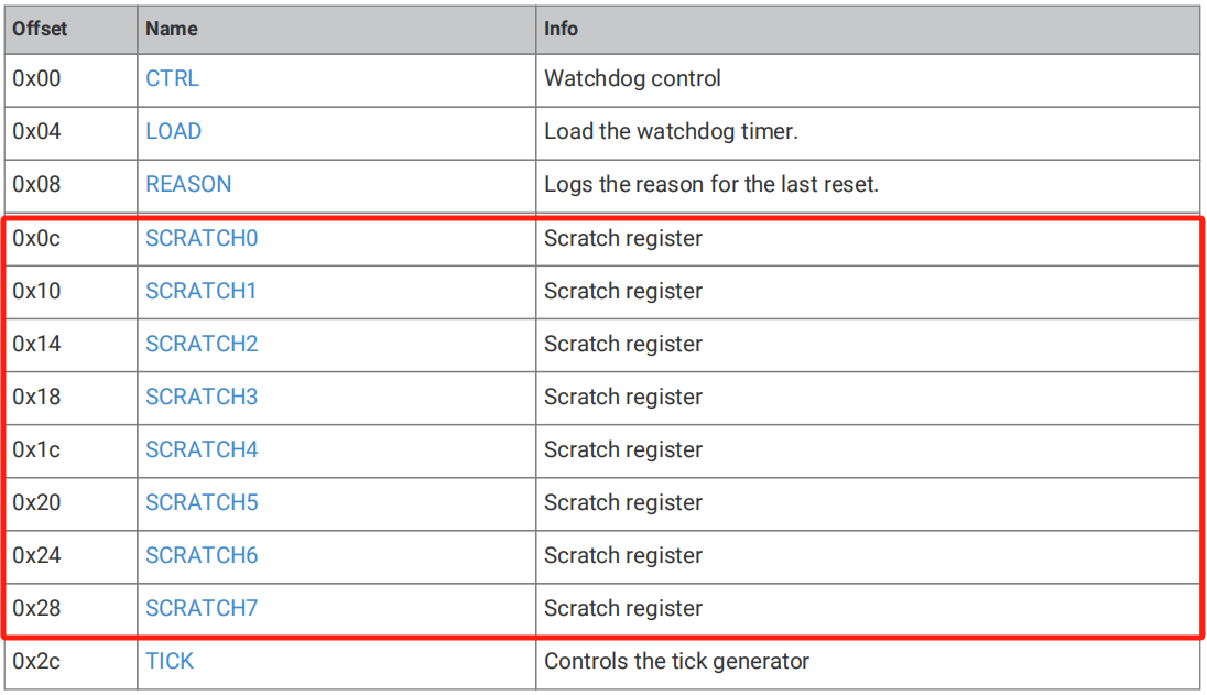

These scratch registers revert to their default initial state only when rst_n_run is asserted, for example by toggling RUN pin or re‑powering DVDD digital‑core supply.
For non‑POR (Power‑On Reset) and non‑BOR (Brown‑Out Reset) resets, users can use scratch registers to specify custom boot‑code behaviour. On startup, Bootrom checks for special magic numbers stored inside scratch registers and decides whether to execute user‑supplied boot code.
Magic number definition: A magic number is a special constant value used for data‑integrity validation, format identification or structure verification.
- Watchdog scratch registers use magic‑number mechanism to decide execution of custom boot code.
- This allows installing custom boot handlers and bypassing normal boot sequence during non‑power‑on resets.
Register assignments:
Scratch 4: stores magic number 0xb007c0d3
Scratch 5: stores entry‑point value XORed with magic number 0xb007c0d3, result equals 0x4ff83f2d
Scratch 6: stores stack pointer value
Scratch 7: stores boot entry‑point address
Bootrom inspects magic‑number values inside Scratch 4 and Scratch 5. If values match expected constants: Bootrom clears Scratch 4 and transfers CPU execution to user‑defined entry‑point address. If magic‑number check fails, Bootrom skips custom boot code and proceeds with standard default boot flow.
This mechanism enables running special‑purpose code at system startup and supports system test‑and‑debug workflows.