Raspberry Pi Pico UART: Hardware, MicroPython & Debugging Guide
This tutorial covers RP2040 UART hardware overview, MicroPython machine.UART APIs, IO multiplexing with select module, and serial debugging tools including CH34
COMPONENTS
PROJECT DESCRIPTION
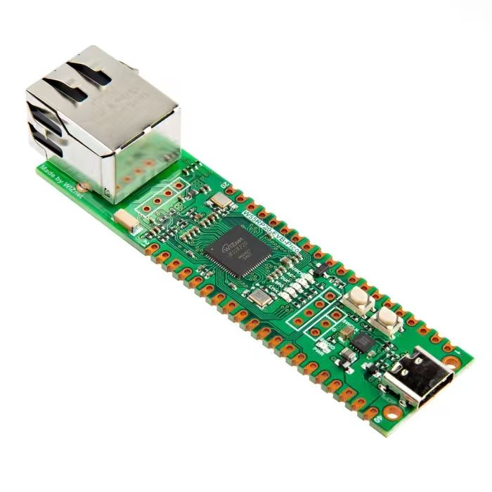
【Preliminary Note】The original hardware example in this article was written based on the RP2040. The actual hardware used in this hands-on demonstration features the W55RP20 as the main controller chip. The circuit logic and UF2 flashing operation principles are universally applicable, with only the main controller model differing. The original chip model mentioned in the circuit descriptions below is provided for reference purposes only.
1. Overview of UART on Raspberry Pi Pico
The Raspberry Pi Pico has two serial port peripherals: UART0 and UART1. Both have identical parameters, and each serial port supports the following functions:
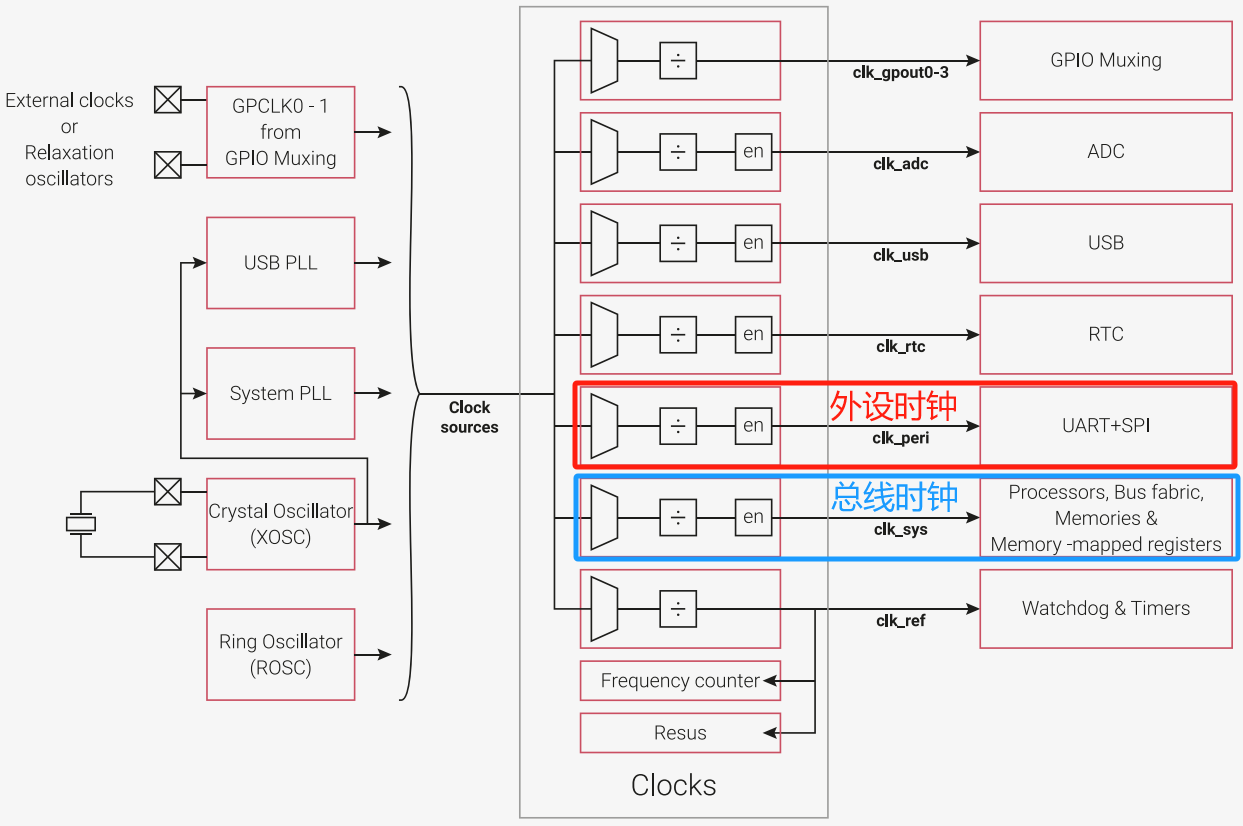
Programmable baud rate generator generated by the clk_peri clock
Standard asynchronous communication bits (start bit, stop bit, parity bit) added during transmission and removed during reception
Wire break detection
The valid data bits can be selected as 5,6, 7 or 8 bits, and the stop bits can be selected as 1 or 2 bits
programmable hardware flow control function
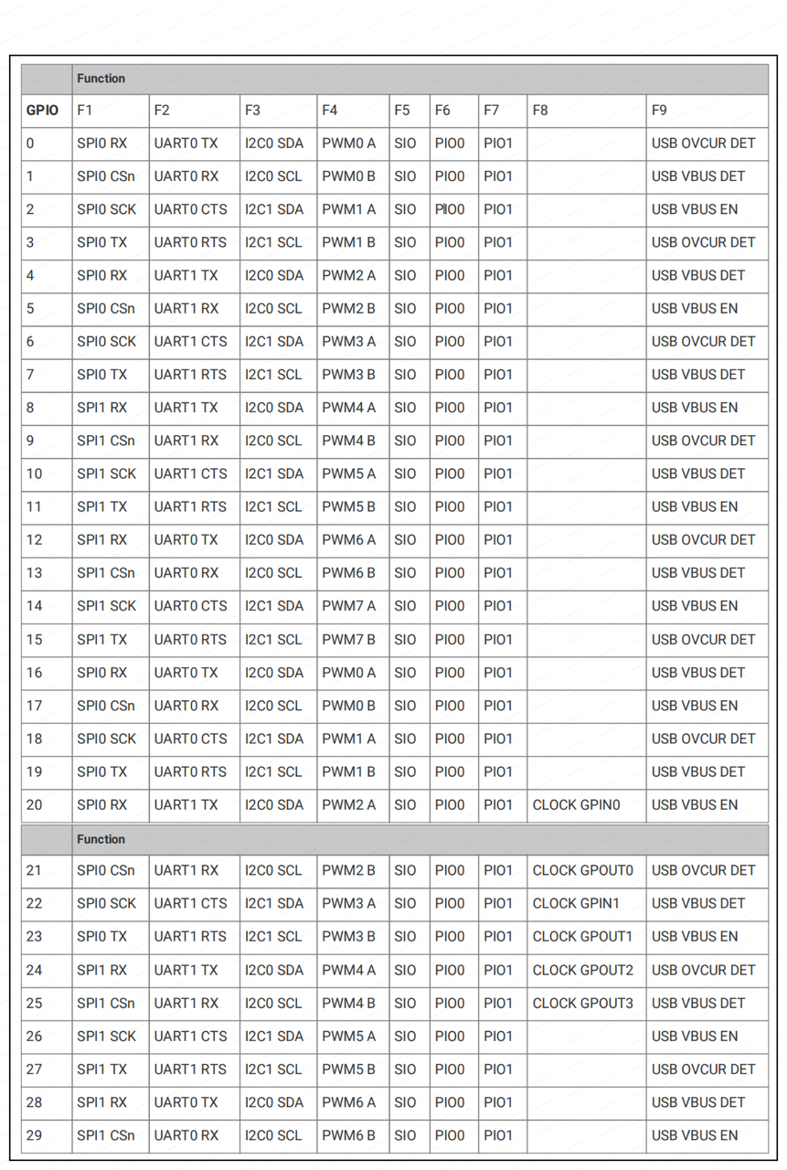
The GPIO pin multiplexing table is as follows:
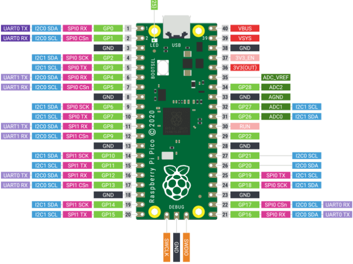
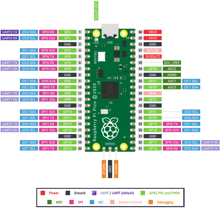
You can also directly check the pinout diagram of the Raspberry Pi Pico:
UART0 can be mapped to GPIO 0/1, GPIO 16/17, and GPIO 21/22
UART1 can be mapped to GPIO 6/7, GPIO 11/12
UART has the following functional pins:
TX Port - UARTnTXD: Used for serial data transmission
RX Terminal - UARTnRXD: Used for receiving serial port data
RTS terminal - nUARTRTS: Output serial port flow control
CTS Terminal - nUARTCTS: Input Serial Port Flow Control
The clock of the serial peripheral, UARTCLK, is driven by the peripheral clock clk_peri, while the clock of the low-speed APB bus, PCLK, is driven by the system clock clk_sys:
The baud rate of serial communication for the Raspberry Pi Pico can be adjusted within the range of 300 bps to 1 Mbps.
2. machine. UART class constructor and initialization method
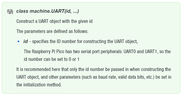
The constructor of the machine. UART class is as follows:
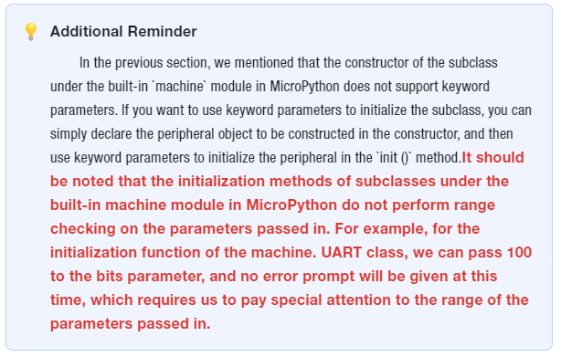
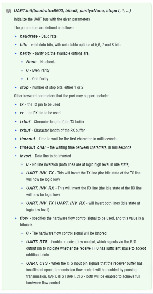
The initialization method of the machine. UART class is as follows:
You can call init () on the same object multiple times to dynamically reconfigure the UART. This feature enables MCU chips with only one UART peripheral to implement time-division multiplexing of the serial port peripheral by configuring connections to different pins through multiple initialization methods. Note that the UART peripheral can only use the two currently specified pins to send and receive data at the same time; meanwhile, do not call deinit (), as it will prevent subsequent calls to init ().
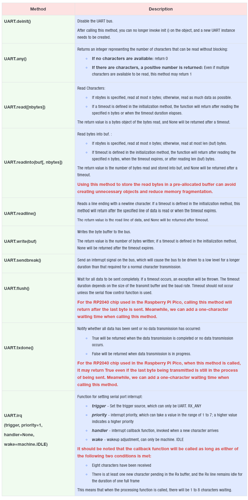
3. Other methods of the machine. UART class
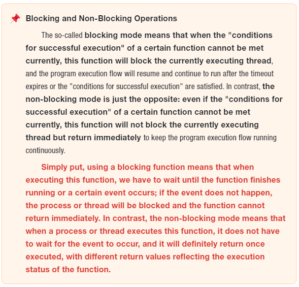
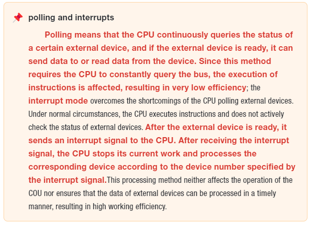
Here, UART. irq is unavailable on the Raspberry Pi Pico microcontroller in MicroPython v1.23.0, but this does not mean that we can only use the blocking method to perform polling to detect whether there is data available to receive in the serial port (i. e., repeatedly execute the UART. any () method and make a judgment based on its return value). We can use coroutines to implement non-blocking serial port reading.
4. select module
Consider the following scenario: we are developing a wireless motion sensor that can detect motion data, sense temperature and humidity data, and transmit the data to a mobile phone via Bluetooth. On the Raspberry Pi Pico, one UART port is connected to a gyroscope sensor, and the other UART port is connected to a temperature and humidity sensor.
At this point, the gyroscope sensor and the temperature and humidity sensor will periodically transmit data to the Raspberry Pi Pico. We need to read the data when it is available, and perform other operations (such as sending the received sensor data to the Bluetooth chip) when there is no data to read. To implement this function, we can continuously use the two UART. any () methods in a while loop for judgment: start receiving when there is data available to receive on either serial port, and only perform other operations after the data has been received.At this point, the program will be stuck waiting for serial port data to be received; if no data is received for a long time (for example, the external temperature and humidity sensor is damaged due to a hardware circuit fault and cannot send data), the program will be blocked.This problem can be solved by running data receiving tasks, data sending tasks and other tasks with multithreading, using coroutines, and using timers to start multiple scheduled execution tasks. However, using the select module to monitor the status changes of the serial port and perform corresponding operations when there is data available for reception is undoubtedly the most concise method. The select module provides an effective way to simultaneously monitor the status of multiple IO objects and perform corresponding processing when there is data to be read or written.
Meanwhile, let's imagine a more complex scenario: the device also requires network communication via a socket to send and receive data. In this case, using other methods to monitor both serial ports and the socket port would be extremely cumbersome and inelegant to implement.
The select module is a module in the Python standard library, which provides the basic function of I/O multiplexing to reuse. In Python, I/O multiplexing refers to the ability to simultaneously monitor the state changes (such as readable, writable, etc.) of multiple file descriptors (e. g., sockets), and perform corresponding operations when any one of the file descriptors is ready. This technology can greatly improve the performance and efficiency of programs when processing a large number of concurrent connections.Using the select module can avoid the overhead of threads or processes, as it can handle multiple I/O events within a single thread. This is extremely critical for high-concurrency network servers, since the creation and destruction of threads or processes consume a large amount of resources.
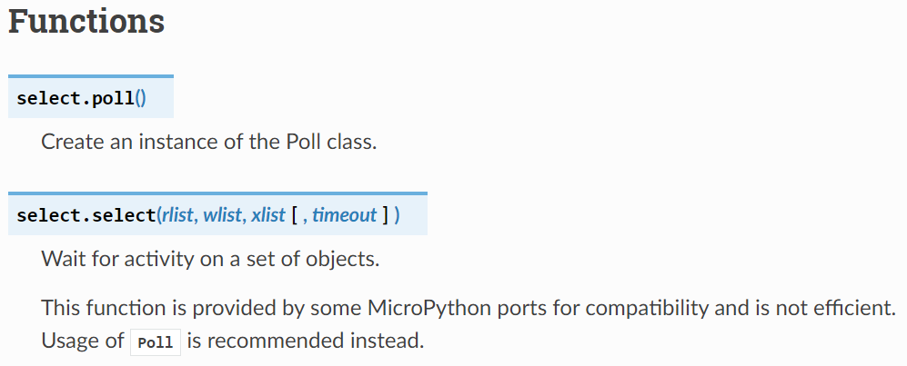
In MicroPython, the select module has the following methods:
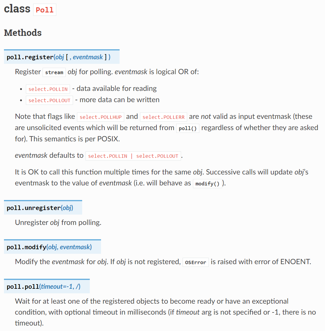
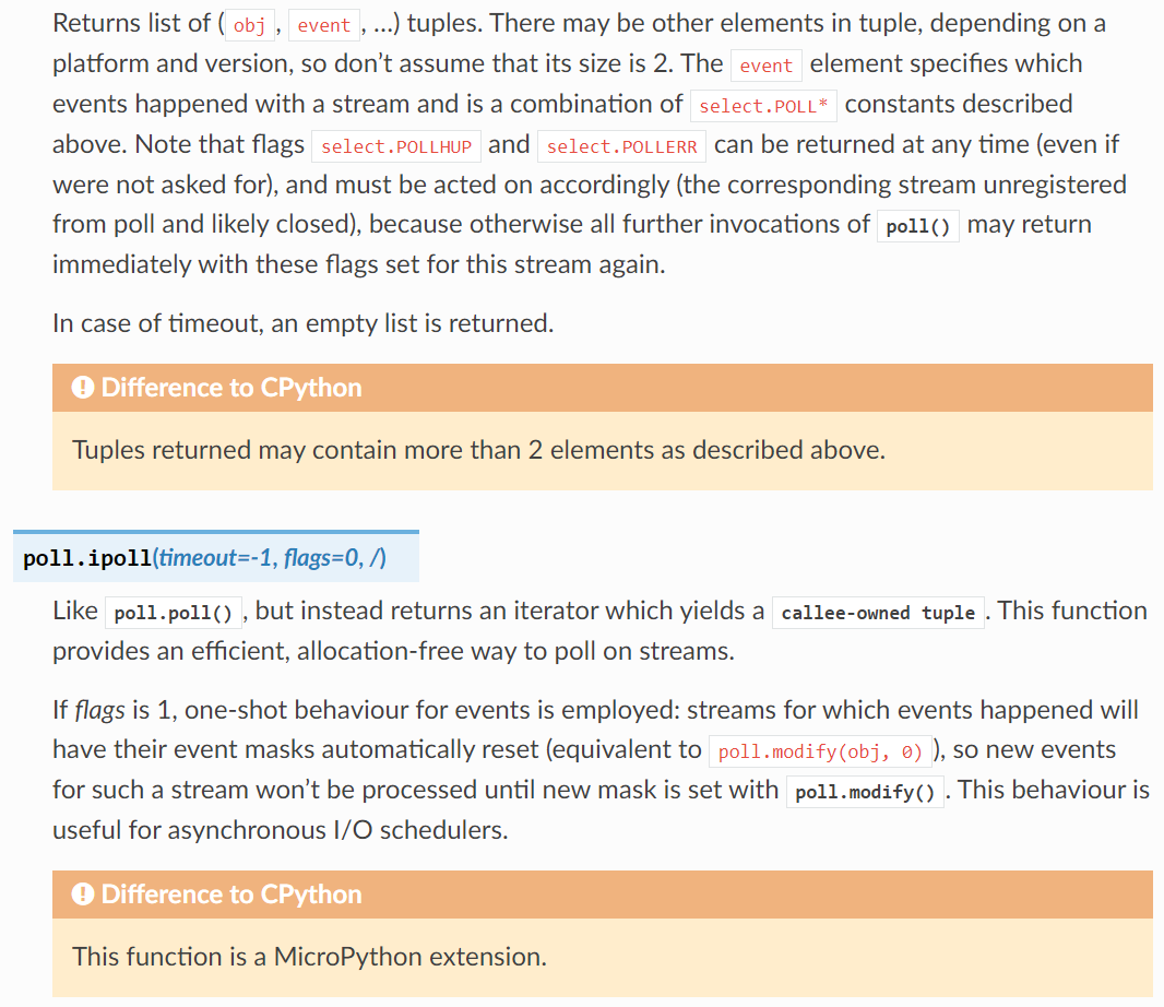
Simply put, we first need to call select. poll () to create an instance of the Poll class, which is the polling object used to monitor devices that read and write data in ByteFlow mode, then use the Poll. register method to register the devices to be monitored with this polling object. After that, we call the Poll. poll method to listen for events; this method will block and wait until one or more devices are ready for I/O operations (such as reading or writing). When an event occurs, the Poll. poll method will return a list containing event objects.Each event object has an `fd` attribute that indicates the device where the event occurs, and an `events` attribute that specifies the event type of the device. We can determine the event type and the corresponding device by reading the `fd` and `events` attributes, then perform the matching operations accordingly.
5. Introduction to CH340 Chip Driver
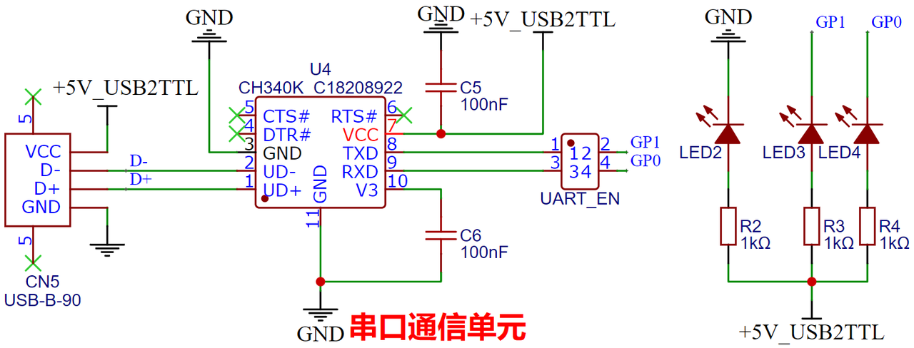
When communicating using the serial port module of a computer and a microcontroller, we need to use a USB-to-TTL chip to convert USB protocol signals into serial Communication Protocol (TTL level) signals. This development board uses the CH340K chip to implement level conversion. The CH340K is a USB-to-serial (TTL) chip launched by Nanjing Qinheng Microelectronics Co. , Ltd. , which integrates an internal oscillator circuit, eliminating the need for external crystals and capacitors, significantly reducing the complexity of peripheral circuits. It also supports a wide range of baud rates, from 300bps to 2Mbps, making it suitable for various communication rate requirements.
The USB-to-TTL level circuit is shown in the following figure:
As a USB peripheral chip, the CH340K requires recognition and support from the operating system to function properly. We must first install the driver for the CH340K chip to enable it to perform serial communication normally. The driver acts as a bridge between the USB protocol and the serial port protocol, allowing applications to communicate with the CH340K chip via a standard serial port interface (COM port).
Here, the driver for the CH340K chip can be downloaded from the following address:
You can also find it in our folder elegance-devkit v1\Development Software\CH340 Driver at the following path:
6. Introduction to XCOM Software
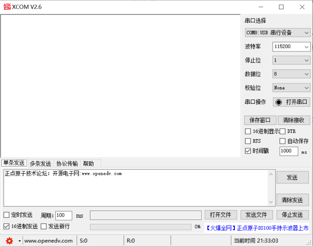
XCOM is a data transmission and debugging tool used in embedded system development, which is typically applied for serial communication between embedded devices and computers. It can display the transmitted and received data of serial communication in real time, supports the configuration of common baud rates, data bits, stop bits and parity bits, and is capable of saving communication data as log files.
The download link for the Wildfire XCOM software is as follows:
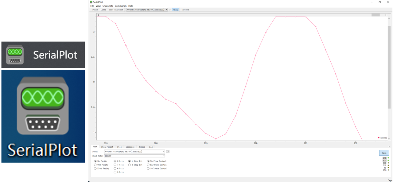
SerialPlot is a debugging tool for real-time plotting of serial port data, which is ideal for monitoring the real-time data transmitted by embedded devices or microcontrollers via the serial port. It can plot the numerical data received from the serial port into charts, making the debugging process more intuitive.
Its basic functions include:
Real-time Plotting: SerialPlot can receive serial port data in real time and plot it into a curve graph
Data Storage: The received data can be saved as a CSV file to facilitate subsequent analysis.
Multi-channel support: capable of parsing multiple data formats including ASCII and binary formats, and supporting the simultaneous plotting of data from multiple channels
For download and installation, please refer to the link: