Raspberry Pi Pico PIO Emulated UART: Full Analysis of Serial Communication Implemented by Arbitrary
This article introduces implementing UART transmit and receive via RP2040 PIO in MicroPython. It covers experimental wiring, PIO assembly logic, code comparison
1. Experiment Preparation
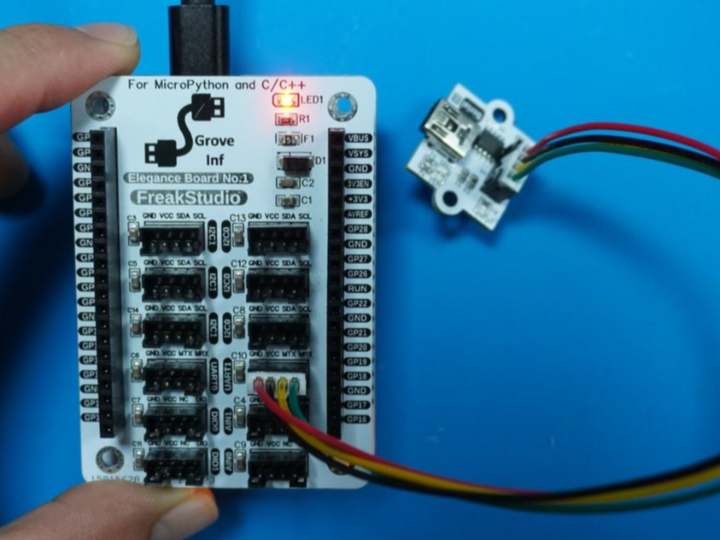
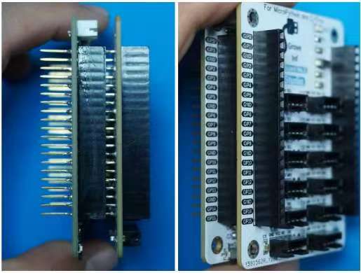
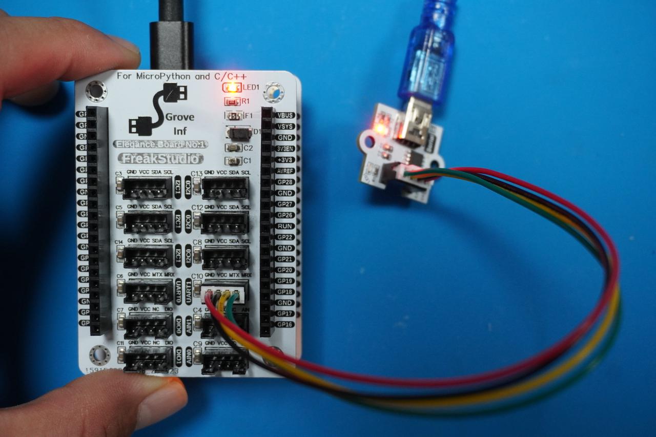
In the following experiments, we need to insert the Fengya One Board - Grove Interface Expansion Board into the Fengya One Board - Universal Compatible Expansion Board, and use a HY2.0-4P cable to connect the UART1 interface on the Fengya One Board - Grove Interface Expansion Board to the GraftSense - CH340K-based USB-to-TTL Module:
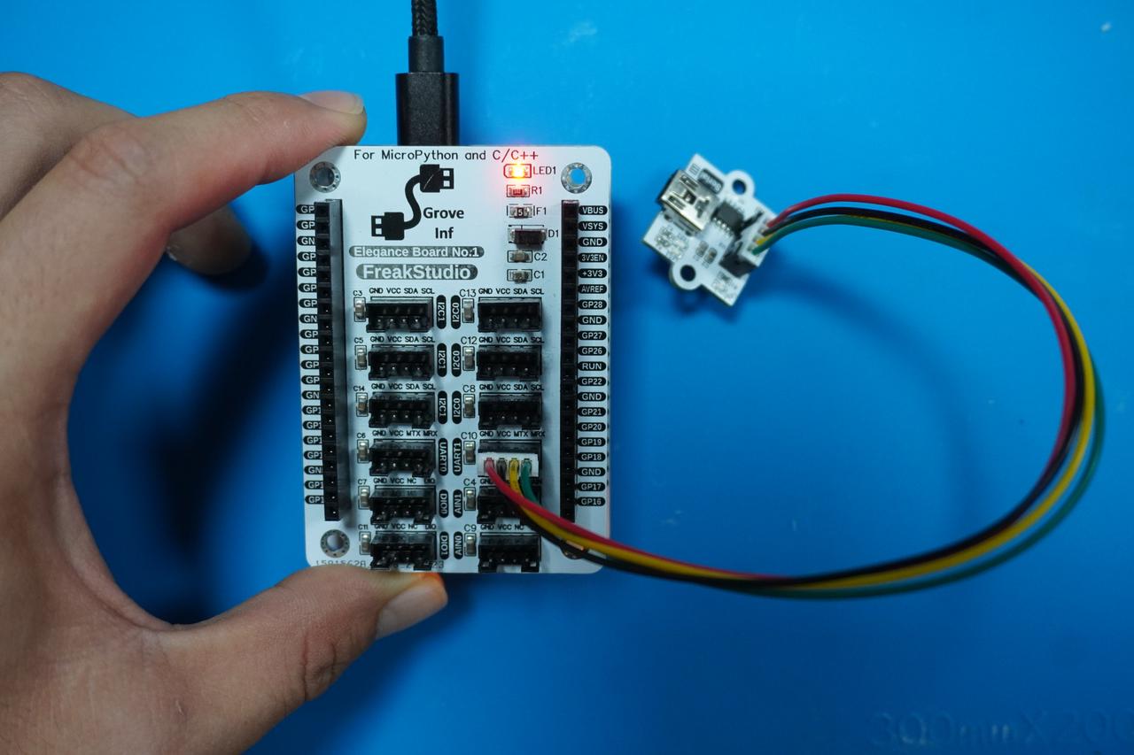
Then use a USB-A to MiniUSB data cable to connect the USB interface on the GraftSense - CH340K-based USB-to-TTL Module to the computer. The physical connection diagram is shown below:
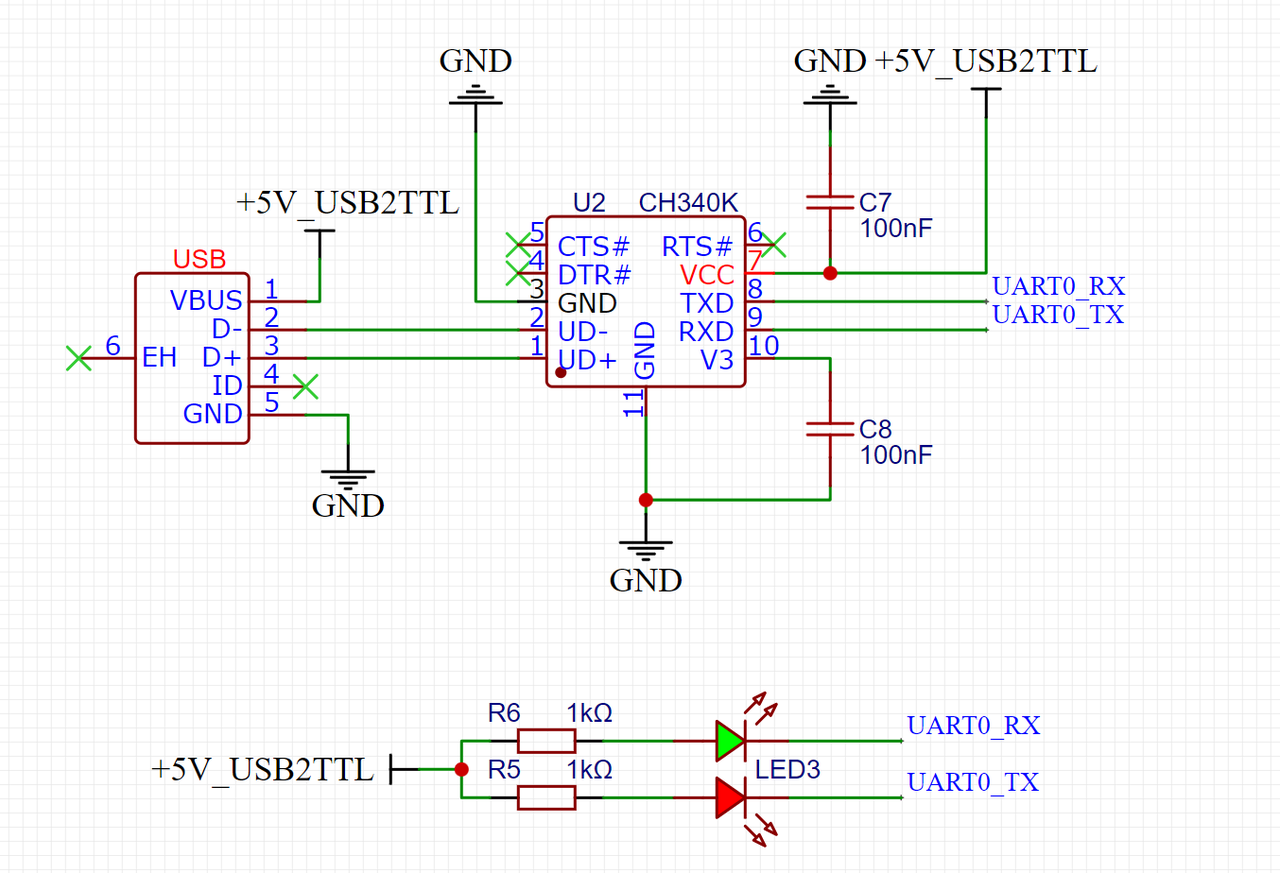
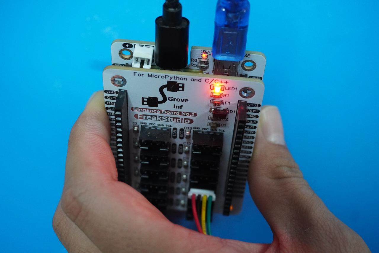
In addition, we first need to connect the MiniUSB data cable to the serial port on the Fengya One Board - Universal Compatible Expansion Board. Here, GP0 and GP1 are the default pins of the Raspberry Pi Pico's hardware UART UART0:
After insertion, the physical diagram is as follows:
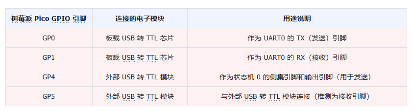
The pin connections are as follows:
2. PIO Implementation of UART Transmit Function
Here, we use PIO to implement the UART serial transmit function. First, let's recall the serial communication protocol. In the simplest case (no parity bit), it consists of 1 start bit, 8 data bits, and 1 stop bit. The bus remains at high level in the idle state:

In the PIO program, we can use the set instruction to set a high or low level to send the start bit and stop bit, and use the out instruction to shift the data to be sent from the TX FIFO into the OSR shift register, thereby sending the data bits. In the MicroPython program, the StateMachine.put() method pushes the data to be sent into the TX FIFO to implement the serial transmit function.
The following code can be found in the elegance-devkit v1\Demo\35 PIO_UART_TX folder in our resource package.
The complete code is as follows:
# Python env : MicroPython v1.23.0
# -*- coding: utf-8 -*-
# @Time : 2024/7/28 1:55 PM
# @Author : Li Qingshui
# @File : main.py
# @Description : PIO experiment: implement UART serial communication in a PIO program
# ======================================== Import related modules ========================================
# Import time-related modules
import time
# Import RP2040-related modules
from rp2 import PIO, StateMachine, asm_pio
# Import hardware-related modules
from machine import Pin, UART
# ======================================== Global variables ============================================
# Defines the UART baud rate as 115200
UART_BAUD = 115200
# Defines the starting pin number used by PIO as 4
PIN_BASE = 4
# Serial transmit counter
UART_TX_COUNT = 0
# ======================================== Function definitions ============================================
# Timing decorator, used to calculate function runtime
def timed_function(f: callable, *args: tuple, **kwargs: dict) -> callable:
"""
Timing decorator, used to calculate and print the runtime of a function/method.
Args:
f (callable): the function/method to be passed in
args (tuple): any number of positional arguments passed to function/method f
kwargs (dict): any number of keyword arguments passed to function/method f
Returns:
callable: returns the timed function
"""
myname = str(f).split(' ')[1]
def new_func(*args: tuple, **kwargs: dict) -> any:
t: int = time.ticks_us()
result = f(*args, **kwargs)
delta: int = time.ticks_diff(time.ticks_us(), t)
print('Function {} Time = {:6.3f}ms'.format(myname, delta / 1000))
return result
return new_func
# Use the @asm_pio decorator to define a PIO program
# The sideset pin is initialized to high level, the OUT pin is initialized to high level, and the output data shift direction is to the right
(sideset_init=PIO.OUT_HIGH, out_init=PIO.OUT_HIGH, out_shiftdir=PIO.SHIFT_RIGHT)
def uart_tx() -> None:
"""
PIO implements UART transmit logic.
Returns:
None
"""
# Take a byte out of the TX FIFO and wait until data is available
pull()
# Initialize the bit counter x to 7 and set the pin low for 7 + 1 cycles, equivalent to sending a start bit
set(x, 7) .side(0) [7]
# Define a label "bitloop" for later jumps
label("bitloop")
# Move a data bit from OSR to pins; the OUT instruction takes one cycle, with a 6-cycle delay, for a total of 6 + 1 = 7 cycles
out(pins, 1) [6]
# Decrement register x by 1; if x is not 0, jump to the bitloop label and continue the data transmission loop
# The jmp instruction takes one cycle, for a total of 7 + 1 = 8 cycles; each bitloop iteration sends one data bit
jmp(x_dec, "bitloop")
# The nop sideset operation sets the pin high and delays 6 cycles, for a total of 6 + 1 = 7 cycles
# The pull instruction takes one cycle, for a total of 7 + 1 = 8 cycles; a stop bit is sent
nop() .side(1) [6]
# The pio_uart_print function is used to send a string via PIO UART
def pio_uart_print(sm: StateMachine, s: str) -> None:
"""
Send a string via PIO UART.
Args:
sm (StateMachine): the PIO state machine instance to use.
s (str): the string to send.
Returns:
None
"""
# Iterate over each character in the string
for c in s:
# Push a word to the state machine's TX FIFO
sm.put(ord(c))
# Send data via the hardware UART peripheral
def hardware_uart_print(uart_obj: UART, s: str) -> None:
"""
Send data via the hardware UART peripheral.
Args:
uart_obj (UART): the UART hardware serial peripheral instance to use.
s (str): the string to send.
Returns:
None
"""
uart_obj.write(s)
# Block until transmission is complete
while not uart.txdone():
pass
# ======================================== Custom classes ============================================
# ======================================== Initialization configuration ==========================================
# Create state machine 0, load the PIO program uart_tx, with a clock frequency of 8 * UART_BAUD, using pin 4 as the sideset pin and output pin
sm = StateMachine(0, uart_tx, freq=8 * UART_BAUD, sideset_base=Pin(PIN_BASE), out_base=Pin(PIN_BASE))
# Start the state machine
sm.active(1)
# Create a serial port instance
uart = UART(0, UART_BAUD)
# Initialize the serial peripheral
uart.init(baudrate = UART_BAUD,
bits = 8,
parity = None,
stop = 1,
tx = 0,
rx = 1,
timeout = 100)
# ======================================== Main program ===========================================
while True:
# Delay 1 second
time.sleep(1)
# Send a string via PIO UART
pio_uart_print(sm, "UART TX DATA\r\n")
# Send a string via the hardware UART peripheral
hardware_uart_print(uart, "UART TX DATA\r\n")In the PIO program part, we did the following:
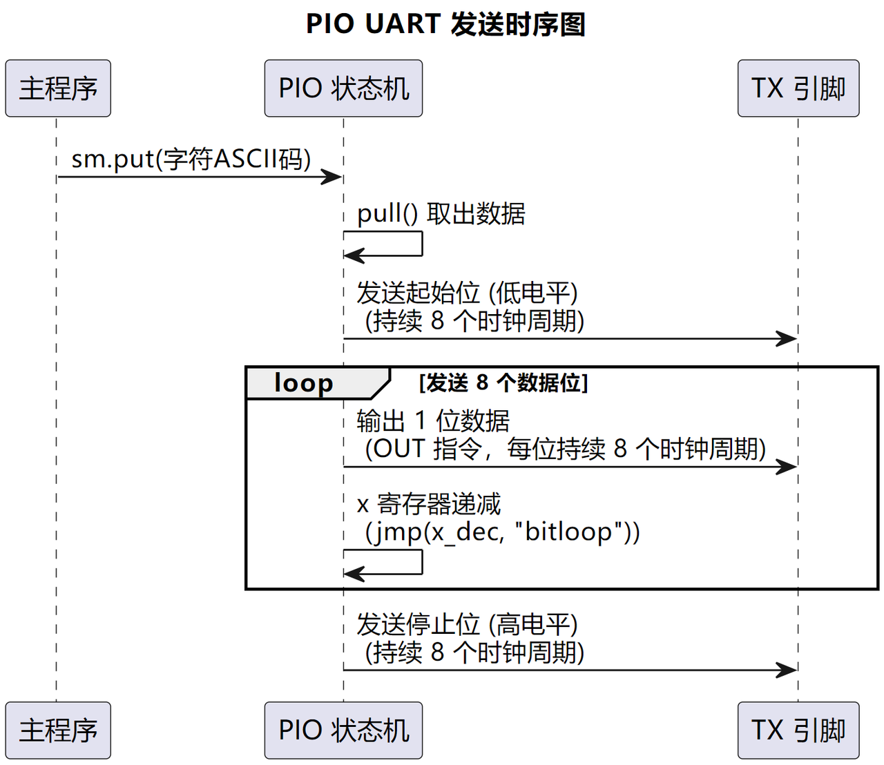
Take a byte out of the TX FIFO: the program first waits until data is available in the TX FIFO. This is implemented with the pull instruction, which checks whether the FIFO is empty; if it is not, it takes one byte of data out of the FIFO.
Initialize the bit counter x: next, the program sets the bit counter x to 7, which means the program will send 8 data bits.
Send the start bit: the program sets the pin low for 7 cycles, plus one extra cycle, to send the start bit. This is implemented with the .side(0) instruction.
Enter the bitloop: the program defines a label named bitloop and starts sending data bits:
Send a data bit: in the bitloop loop, the program moves a data bit from the output shift register (OSR) to the pin. This is done with the out(pins, 1) instruction, which takes one cycle, and the program delays 6 more cycles afterwards.
Decrement the bit counter x: after each data bit is sent, the program decrements the bit counter x by 1.
Check whether all data bits have been sent: if the bit counter x is not 0, the program jumps back to the bitloop label and continues sending the next data bit. Otherwise, the program exits the loop.
Send the stop bit: after all data bits have been sent, the program sends a stop bit. This is implemented with the nop() instruction, which takes one clock cycle. Then the program delays 6 more cycles; together with the pull instruction, the total delay is 8 cycles, and one stop bit is sent.
Here, we set the PIO state machine clock to 8 * UART_BAUD to ensure correct UART timing. In the main loop, we use the pio_uart_print() function and the hardware_uart_print() function to send the same string through the PIO and hardware UART peripherals respectively, and compare their execution speeds.
After flashing the code and opening the remote terminal, you can see the execution speeds of the two functions:
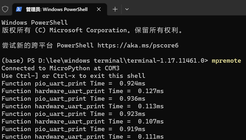
Here, you can see that sending 14 bytes of data via the PIO-implemented UART takes 0.924ms = 924us. At a baud rate of 115200, the time to send one byte of data is 8/115200 s = 69.4 us, so the time to send 14 bytes should be 69.4 * 14 ≈ 896 us, which is close to the time taken by the PIO-implemented UART to send 14 bytes (considering interpreter overhead such as type checking and function calls).
We can see that sending 14 bytes of data via the hardware UART peripheral takes 0.127 ms. Note that this is not the actual UART transmission time, but the time taken by MicroPython to execute and call the underlying C functions:
First, the pointer to the string s is passed to the hardware UART C language driver.
The driver copies the data into the UART hardware FIFO buffer.
It returns immediately, without waiting for all data to be transmitted.
Here, the @timed_function decorator only records the time of Python, C interface calls + copying data into the FIFO, not the physical layer transmission time.
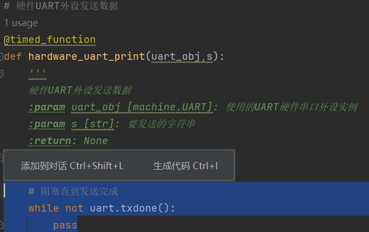
If you want to measure the real transmission time of the hardware UART, you can remove the following commented-out code that waits for the serial transmission to complete:
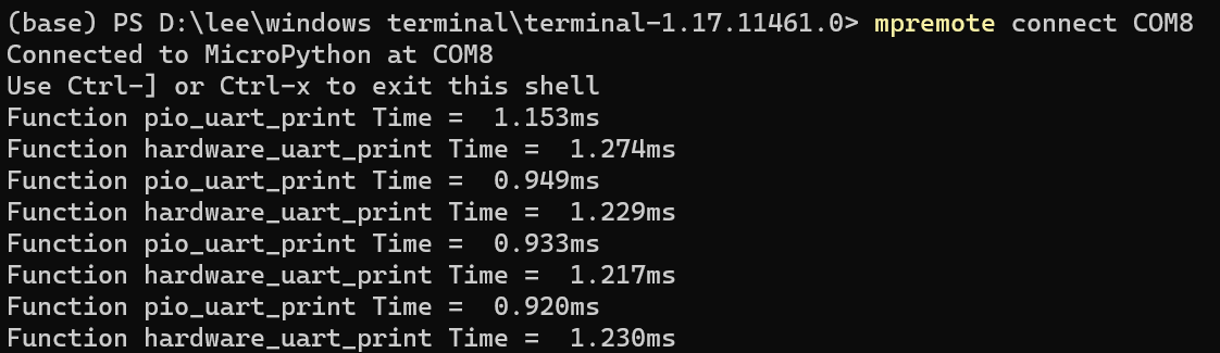
Run it again; you can see that the terminal outputs a serial transmission completion time of about 1.2 ms:
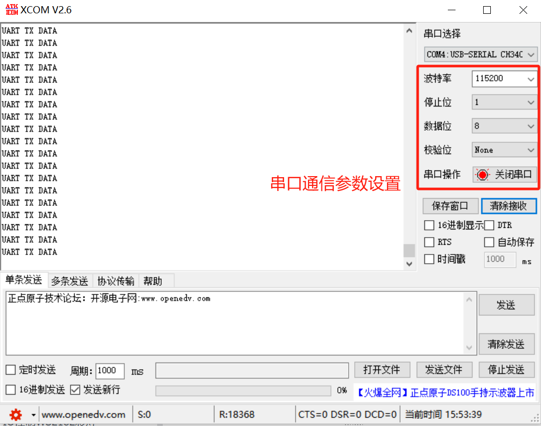
Connect the GraftSense - CH340K-based USB-to-TTL Module to the computer with a data cable, open the xcom serial assistant, and we can see that the PIO-implemented UART transmit function works normally:
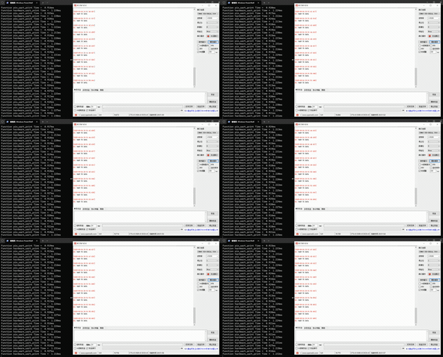
Compared with using the hardware UART peripheral for serial communication, implementing serial communication with PIO has the following advantages:
Support for any pin: PIO can use any GPIO pin as the serial transmit pin, while hardware UART is usually bound to specific pins. In addition, a single PIO block can implement multiple serial transmit channels at the same time (for example, 4 state machines implementing 4 UART TX channels), while the number of hardware UARTs is limited (for example, RP2040 only has 2 hardware UARTs).
Flexible expansion: PIO can implement non-standard communication methods such as half-duplex, full-duplex, and single-wire serial, and can also implement complex frame formats (such as adding custom preambles, CRC checks, etc.). Since every pin on the Raspberry Pi Pico supports PIO, this can greatly reduce the complexity of PCB layout when designing our own circuit boards.
3. PIO Implementation of UART Receive Function
Here, we use PIO to implement the UART serial receive function. First, let's recall the serial communication protocol. In the simplest case (no parity bit), it consists of 1 start bit, 8 data bits, and 1 stop bit. The bus stays at high level in the idle state:

When communication starts, the bus jumps from idle high level to low level; this low level is the start bit. Then 8 data bits are transmitted in sequence (from LSB to MSB in the timing diagram). After the data bits are transmitted, the bus returns to high level; this high level is the stop bit, marking the completion of one frame of data reception.
In the PIO program, we can:
Use the wait instruction to detect the start bit (wait for the pin to go low);
Use the in_ instruction to read the pin level into the ISR shift register, thereby obtaining the data bits;
Use the jmp instruction to check whether the stop bit is high (to ensure valid communication); if the stop bit is normal, use the push instruction to push the data in the ISR into the RX FIFO.
In the MicroPython program, use the StateMachine.get() method to read the received data from the RX FIFO, completing the serial receive function.
The following code can be found in the elegance-devkit v1\Demo\76 PIO_UART_RX folder in our resource package.
The complete code is as follows:
# Python env : MicroPython v1.23.0
# -*- coding: utf-8 -*-
# @Time : 2025/12/23 3:56 PM
# @Author : Li Qingshui
# @File : main.py
# @Description : PIO experiment: implement UART serial reception
# ======================================== Import related modules ========================================
import time
from rp2 import PIO, StateMachine, asm_pio
from machine import Pin, UART
# ======================================== Global variables ============================================
# Defines the UART baud rate as 115200
UART_BAUD = 115200
# Defines the pin number used for PIO UART reception as 5 (GP5)
PIO_RX_PIN_NUM = 5
# Defines the terminator for the received serial string
UART_TERMINATOR = '\r'
# Defines the maximum length of the received serial string (to prevent buffer overflow)
UART_MAX_STR_LEN = 128
# ======================================== Function definitions ============================================
# Timing decorator, used to calculate function runtime
def timed_function(f: callable, *args: tuple, **kwargs: dict) -> callable:
"""
Timing decorator, used to calculate and print the runtime of a function/method.
Args:
f (callable): the function/method to be passed in
args (tuple): any number of positional arguments passed to function/method f
kwargs (dict): any number of keyword arguments passed to function/method f
Returns:
callable: returns the timed function
"""
myname = str(f).split(' ')[1]
def new_func(*args: tuple, **kwargs: dict) -> any:
t: int = time.ticks_us()
result = f(*args, **kwargs)
delta: int = time.ticks_diff(time.ticks_us(), t)
print('Function {} Time = {:6.3f}ms'.format(myname, delta / 1000))
return result
return new_func
# Use the @asm_pio decorator to define a PIO program
# The input data shift direction is to the right
(in_shiftdir=PIO.SHIFT_RIGHT)
def uart_rx() -> None:
"""
PIO implements UART receive logic (8 data bits, 1 start bit, 1 stop bit).
Returns:
None
"""
label("start")
# Wait for the start bit (low level)
wait(0, pin, 0)
# Set the data counter x to 7 (8 data bits in total) and delay to the middle of the first data bit (10 cycles)
set(x, 7) [10]
# Loop to read 8 data bits
label("bitloop")
in_(pins, 1)
jmp(x_dec, "bitloop") [6]
# Check the stop bit (high level is normal)
jmp(pin, "good_stop")
# Stop bit error: trigger an interrupt, wait for the pin to go idle, and discard the data
irq(block, 4)
wait(1, pin, 0)
jmp("start")
# Stop bit is normal: push the data to the FIFO (block means blocking until the FIFO has space)
label("good_stop")
push(block)
def uart_break_handler(sm: StateMachine) -> None:
"""
Interrupt handler when PIO detects a serial frame error/stop bit error.
Args:
sm (StateMachine): the PIO state machine instance that triggered the interrupt
Returns:
None
"""
print("Recv Break/Frame Error at: {}ms".format(time.ticks_ms()))
def pio_uart_read_byte(sm: StateMachine) -> int:
"""
Read one UART-received byte from the PIO state machine (with timing decorator).
Args:
sm (StateMachine): the PIO state machine instance to use
Returns:
int: the received 8-bit byte data (0-255)
"""
# Read 32-bit data from the PIO FIFO and shift right by 24 bits to extract the valid 8 bits (because right-shifted data is stored in the high 8 bits)
received_data = sm.get()
received_byte = received_data >> 24
return received_byte
def pio_uart_read_string(sm: StateMachine, max_length: int = UART_MAX_STR_LEN, terminator: str = UART_TERMINATOR) -> str:
"""
Read a UART-received string from the PIO state machine (until the terminator or maximum length).
Args:
sm (StateMachine): the PIO state machine instance to use
max_length (int, optional): maximum read length, to prevent infinite blocking. Default is UART_MAX_STR_LEN
terminator (str, optional): string terminator (e.g. newline). Default is UART_TERMINATOR
Returns:
str: the received string
"""
received_chars = []
current_length = 0
# Loop to read bytes until the maximum length is reached or the terminator is encountered
while current_length < max_length:
byte = pio_uart_read_byte(sm)
char = chr(byte)
received_chars.append(char)
current_length += 1
# Stop reading when the terminator is encountered
if char == terminator:
break
# Join the characters into a string and return it
return ''.join(received_chars)
# ======================================== Custom classes ============================================
# ======================================== Initialization configuration ==========================================
# Initialize the PIO receive pin (pull-up input, to prevent floating)
pio_rx_pin = Pin(PIO_RX_PIN_NUM, Pin.IN, Pin.PULL_UP)
# Create PIO state machine 0, load the uart_rx program, with a clock frequency of 8*UART_BAUD (multiplied frequency to match the timing)
# in_base: the starting number of the input pins; jmp_pin: the pin used for jump decisions (same as the input pin)
sm = StateMachine(
0,
uart_rx,
freq=8 * UART_BAUD,
in_base=pio_rx_pin,
jmp_pin=pio_rx_pin
)
# Bind the interrupt handler (triggered on receive errors)
sm.irq(uart_break_handler)
# Activate the state machine (start receiving data)
sm.active(1)
# ======================================== Main program ===========================================
while True:
# Read a string (until the newline) and print it
received_str = pio_uart_read_string(sm)
print("Received String: {}".format(received_str))In the PIO program part, we did the following:
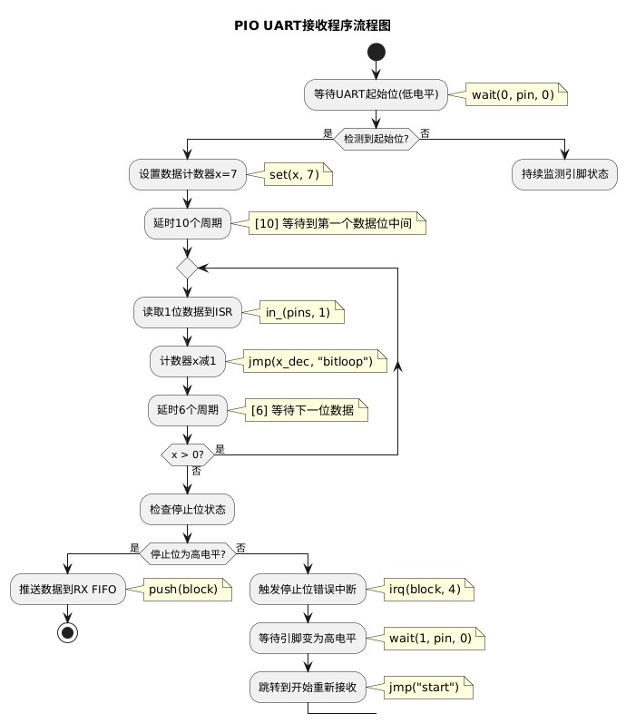
Wait for the start bit: use the wait(0, pin, 0) instruction to continuously monitor the pin state until the pin jumps from idle high level to low level (i.e., the UART start bit), and only then proceed to the next step;
Initialization and delay alignment: use set(x, 7) to set the data counter x (corresponding to counting the 8 data bits), and use [10] to delay 10 cycles, ensuring that the sampling timing is aligned to the middle of the first data bit to improve sampling accuracy;
Read data bits in a loop: use label("bitloop") to define the loop label, use in_(pins, 1) to read the current pin level into the ISR shift register, then use jmp(x_dec, "bitloop") to decrement counter x and jump back to the loop (until x reaches 0), while using [6] to delay 6 cycles to wait for the sampling timing of the next data bit, completing the reading of the 8 data bits;
Stop bit check and data processing: after reading the data bits, check whether the pin is at high level (i.e., the UART stop bit):
If the stop bit is high, execute the push(block) instruction to push the 8 bits of data stored in the ISR to the RX FIFO for the subsequent program to read;
If the stop bit is abnormal (not high), trigger a stop bit error interrupt with irq(block, 4), then use wait(1, pin, 0) to wait for the pin to return to high level, and use jmp("start") to jump back to the start position and restart the receive process.
Here, we also defined two functions:
def uart_break_handler(sm: StateMachine) -> None:
"""
Interrupt handler when PIO detects a serial frame error/stop bit error.
Args:
sm (StateMachine): the PIO state machine instance that triggered the interrupt
Returns:
None
"""
print("Recv Break/Frame Error at: {}ms".format(time.ticks_ms()))
def pio_uart_read_byte(sm: StateMachine) -> int:
"""
Read one UART-received byte from the PIO state machine (with timing decorator).
Args:
sm (StateMachine): the PIO state machine instance to use
Returns:
int: the received 8-bit byte data (0-255)
"""
# Read 32-bit data from the PIO FIFO and shift right by 24 bits to extract the valid 8 bits (because right-shifted data is stored in the high 8 bits)
received_data = sm.get()
received_byte = received_data >> 24
return received_byteAmong them:
The serial error interrupt handler uart_break_handler: this function is the interrupt callback of the PIO state machine, dedicated to handling frame errors (stop bit errors) that occur during serial reception. When the PIO assembly program detects that the stop bit is not high (serial frame error / break signal), it triggers an interrupt;
The byte reading function pio_uart_read_byte: this function is the core data reading interface for PIO UART reception. It reads and parses one 8-bit UART-received byte from the RX FIFO of the PIO state machine.
In actual serial communication scenarios, we rarely need to receive only a single byte; more often we need to receive strings (such as a line of instructions or a piece of text sent by the user). If we manually loop to call pio_uart_read_byte each time to read bytes and then manually concatenate them into a string, it becomes very tedious. For convenience, we also wrapped a pio_uart_read_string function:
def pio_uart_read_string(sm: StateMachine, max_length: int = UART_MAX_STR_LEN, terminator: str = UART_TERMINATOR) -> str:
"""
Read a UART-received string from the PIO state machine (until the terminator or maximum length).
Args:
sm (StateMachine): the PIO state machine instance to use
max_length (int, optional): maximum read length, to prevent infinite blocking. Default is UART_MAX_STR_LEN
terminator (str, optional): string terminator (e.g. newline). Default is UART_TERMINATOR
Returns:
str: the received string
"""
received_chars = []
current_length = 0
# Loop to read bytes until the maximum length is reached or the terminator is encountered
while current_length < max_length:
byte = pio_uart_read_byte(sm)
char = chr(byte)
received_chars.append(char)
current_length += 1
# Stop reading when the terminator is encountered
if char == terminator:
break
# Join the characters into a string and return it
return ''.join(received_chars)Its working principle is:
It continuously calls the underlying timed function pio_uart_read_byte to read a single byte of data from the PIO state machine's RX FIFO, converts it into the corresponding character, stores it in the character list, and accumulates the character length;
During the loop, the function checks two termination conditions in real time:
One is whether the current received character length reaches the preset max_length (by default specified by the global constant UART_MAX_STR_LEN, to prevent the program from blocking indefinitely);
The other is whether the preset terminator has been read (by default the newline character \n, which is a common string end marker in serial communication).
As long as either condition is met, the loop terminates immediately;
Finally, the function joins the character list into a complete string and returns it, thereby implementing direct reading of a complete string from the PIO UART, without the developer manually handling byte concatenation and termination detection details.
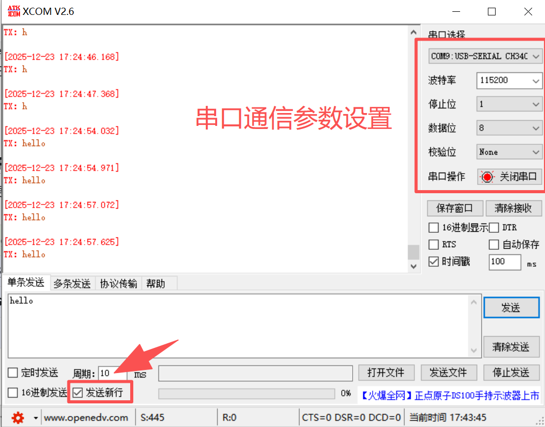
Here, we first connect the GraftSense - CH340K-based USB-to-TTL Module to the computer with a data cable, open the xcom serial assistant, and remember to click "Send Newline":
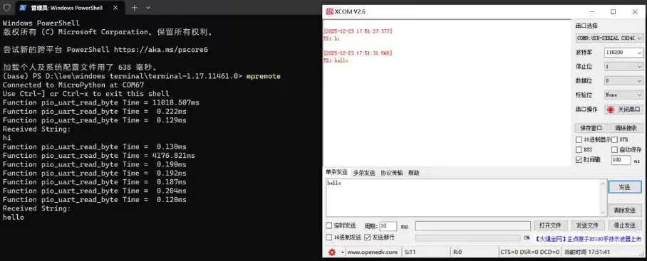
Then flash the code, open the remote terminal, send data in the xcom serial assistant, and the terminal output is as follows: