Quick Start with Blockless to Realize Hardware Creations
This guide shows how to build and test a light-controlled LED system using Blockless and the W5100S-EVB-Pico.
COMPONENTS
PROJECT DESCRIPTION
【Preliminary Note】The original hardware example in this article was written based on the RP2040. The actual hardware used in this hands-on demonstration features the W55RP20 as the main controller chip. The circuit logic and UF2 flashing operation principles are universally applicable, with only the main controller model differing. The original chip model mentioned in the circuit descriptions below is provided for reference purposes only.
This paper takes the "light-controlled LED system" as a case to introduce how to use Blockless to complete the requirement analysis, hardware selection, interface judgment, pin assignment, project generation, code understanding and real machine verification of an embedded project.
In this case, the W5100S-EVB-Pico is used as the main controller, connected to the GL5516 photosensitive module, the piranha LED module, and the SSD1306 OLED module with I2C interface. The system reads changes in ambient light: it automatically turns on the LEDs when the environment darkens, and automatically turns off the LEDs when the environment brightens; meanwhile, it displays the light intensity data, ambient status and LED status on the OLED, and outputs operation information via the serial port.
This article not only focuses on completing a single Blockless operation, but also illustrates how an embedded project can gradually complete hardware selection, interface confirmation and pin planning based on requirements. When project requirements change, readers can also re-select appropriate main control and peripheral solutions accordingly.
1. Project Requirements and Overall Solution
1.1 Project Objectives and Acceptance Criteria
This project aims to develop a small system that automatically turns on the light according to the ambient brightness.
The photosensitive module acts as the "eyes" of the system, capable of detecting changes in the surrounding light. When the ambient light dims — for instance, when you cover the photosensitive module with your hand — the system will determine that the current light level is insufficient and automatically turn on the LED; once you remove your hand and the surroundings brighten up again, the LED will switch off automatically.
An OLED screen acts as a tiny information window, displaying the current light intensity value, whether the surrounding environment is bright or dim, and whether the LED is currently on or off.
The program also outputs runtime information via the serial port. This way, even if relatively little content is displayed on the screen, you can still check on a computer whether the program has started, how much light intensity data has been read so far, and whether the status of the LED has changed.
After completing the project, you can check whether the system works properly in the following way:
Cover the photosensitive module with your hand and check whether the LED lights up automatically;
Remove your hand to let the photosensitive module re-expose to light, and observe whether the LED turns off automatically;
Check whether the OLED displays the light intensity value, ambient brightness status and LED status;
Check whether information such as program startup, light reading, and LED status changes can be seen in the serial port;
Repeatedly block and unblock the photosensitive module, and check whether the LED can be switched on and off normally each time.
1.2 What you will master after completing this case
After completing this case, readers will master the basic methods from project requirements to actual machine verification.
First, readers can decompose natural language requirements such as "automatically turn on the light when the environment darkens" into functions including input, processing, output and display. Second, readers can select appropriate main controllers and peripherals according to conditions such as whether the project requires network connection, which peripheral interfaces are needed, and whether analog signal acquisition is required.
After completing hardware selection, readers can also determine whether different modules should use ADC, GPIO or I2C interfaces, and complete pin assignment and conflict check according to interface requirements. Finally, readers can input complete requirements in Blockless, review the recommended scheme, generate a project, and verify whether the functions are realized through real machine tests.
Therefore, when subsequent projects have requirements such as temperature and humidity monitoring, EA IOT Lighting, and networked Data Acquisition, the scheme design can also be completed again following the same process.
1.3 Project Function Decomposition
Before selecting a development board and peripherals, it is necessary to clarify the responsibilities of each functional component in the project first. For most embedded projects, you can first break down the requirements in accordance with the approach of "input, processing, output, display and debugging".
Function Category
Project Module
Main Task
Resources to Confirm Later
Input
GL5516 Light Sensor Module
Detect ambient light changes
Whether to use analog output or digital output
Processing
W5100S-EVB-Pico
Read data and perform threshold comparison
ADC, GPIO, program logic
Output
Piranha LED Module
Turn the LED on or off based on the result
GPIO output
Display
SSD1306 OLED
Display data and status
I2C interface
Debugging
USB Serial Port
Output runtime logs
USB and serial tools
Through functional decomposition, it can be found that the photosensitive module does not "directly control the LED", but is responsible for providing input data; the W5100S-EVB-Pico is responsible for processing data and making judgments; the LED is responsible for executing the control results; and the OLED and serial port are responsible for feeding back the system status to the user.
This splitting method can be migrated to other projects. For example, in a temperature and humidity monitoring project, the temperature and humidity sensor can be used as the input, the main control unit as the processing unit, the buzzer or relay as the output, and the OLED, web page or mobile terminal as the display and feedback method.
1.4 System Workflow
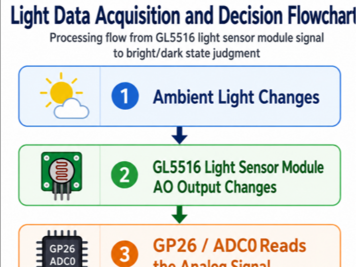
After the system is powered on, the W5100S-EVB-Pico first initializes the photosensitive module, LED module, OLED module and serial port. The program then periodically reads the illumination data from the photosensitive module and compares the reading with a preset threshold.
When it is determined that the environment darkens, the program turns on the LED, and outputs status information such as "The environment is relatively dark, LED has been turned on" on the OLED display and through the serial port; when it is determined that the environment brightens, the program turns off the LED, and updates the information on the OLED display and the serial port synchronously.
It should be noted that the actual threshold, the direction of reading change, and the sampling period shall be subject to the finally generated code and the actual machine test data, and shall not be assumed in advance during case writing.
2. Let Blockless Help You with hardware Selection
For users who are just getting started with hardware projects, the most difficult part is often not writing code, but figuring out which development board to choose, which modules are required, and which pins those modules should be connected to.
Blockless's Beginner mode integrates these issues that originally required separate handling into a single process: users first describe the functions they want to implement, then the plugin analyzes the requirements, recommends development boards and components, and generates interface and pinout schemes. Users do not need to manually complete all hardware configurations from scratch, but they need to understand the recommended results and confirm whether they are consistent with their project objectives and actual hardware.
This chapter will explain how users with different levels of experience can start the model selection process, what recommended results Blockless will provide, and how to re-obtain a suitable new solution when the project requirements change.
2.1 How different users should start the model selection process
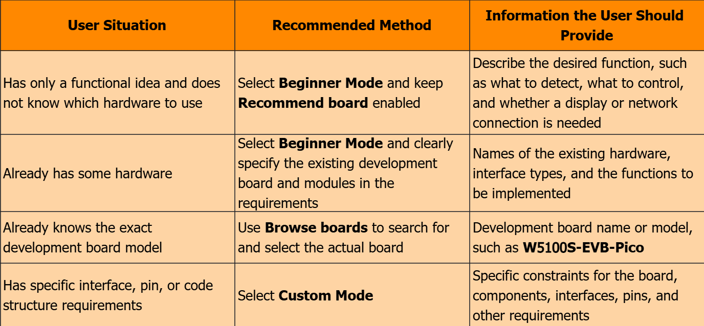
When starting to create a hardware project, different users have varying levels of information at their disposal. Some users only have a functional idea, such as "automatically turn on the lights when the environment gets dark"; some users already have W5100S-EVB-Pico, sensors or display screens ready; and there are also some users who already know which development board they need to use.
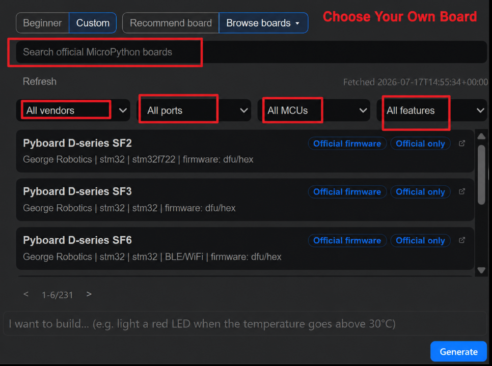
Blockless provides entry points such as Beginner, Custom, Recommend board and Browse boards, allowing users to choose an appropriate starting method based on the information they currently have.
User Situation
Recommended Method
Information the User Should Provide
Has only a functional idea and does not know which hardware to use
Select Beginner Mode and keep Recommend board enabled
Describe the desired function, such as what to detect, what to control, and whether a display or network connection is needed
Already has some hardware
Select Beginner Mode and clearly specify the existing development board and modules in the requirements
Names of the existing hardware, interface types, and the functions to be implemented
Already knows the exact development board model
Use Browse boards to search for and select the actual board
Development board name or model, such as W5100S-EVB-Pico
Has specific interface, pin, or code structure requirements
Select Custom Mode
Specific constraints for the board, components, interfaces, pins, and other requirements
users who only have functional ideas
For example, a user may only know that they "want the lights to turn on automatically when the environment gets dark", but have no idea which development board, sensor or display module to use. In this case, it is recommended to select the Beginner mode and use the Recommend board. Users only need to describe the functions they want to achieve, and Blockless will analyze the requirements and recommend suitable development boards and components.
Users who have already prepared some hardware
If users already have a development board, sensors or display modules, they should specify the existing hardware in the requirements. For example, this case has prepared the W5100S-EVB-Pico, GL5516 photosensitive module, piranha LED, and SSD1306 OLED. In this way, Blockless will generate a solution based on the existing hardware instead of recommending components that the user has not prepared.
Users who already know the model of the development board
If you already know exactly which development board to use, you can use Browse boards to search for and confirm the actual board. For example, the W5100S-EVB-Pico is used in this case, and you can find the corresponding board by searching for Pico. There may be boards with similar names in the search results, so you need to confirm that the name matches the physical board you have.
Users with specific configuration requirements
If users already know clearly which devices, interfaces or pins they need to use, they can also use the Custom mode to further adjust the configuration. For users who are using Blockless for the first time, it is recommended to first complete a full project via the Beginner mode, and then try the Custom mode step by step.
2.2 How Blockless Recommends Development Boards and Components
After a user submits a requirement, Blockless will analyze the functions that the project needs to implement and recommend suitable development boards and components. The recommendation result does not require the user to accept it completely as it is, but rather provides the user with an initial solution that can be confirmed and adjusted.
Recommended Development Boards by Function
When the user does not specify a development board, Blockless will recommend a development board based on the input, output, display and communication requirements in the demand. For example, this case requires reading ambient light, controlling LEDs, and connecting to an OLED, but has no networking requirements, so the plugin recommends the W5100S-EVB-Pico.
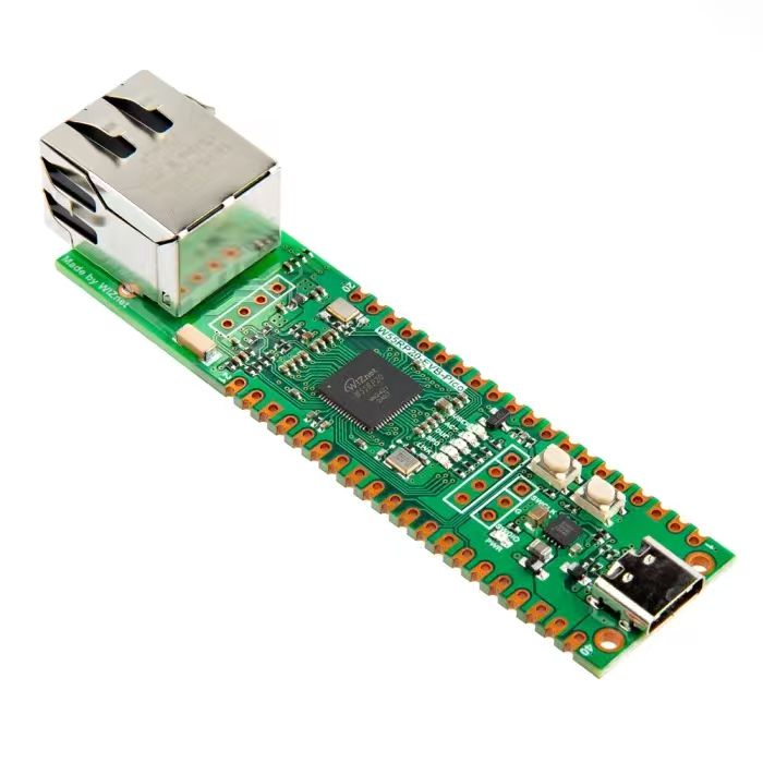
This case selects W5100S-EVB-Pico as the main control, and the main control chip is RP2040.
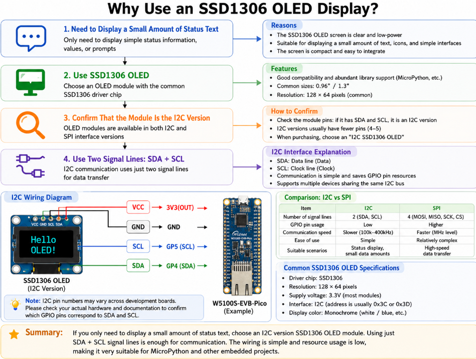
The W5100S-EVB-Pico provides versatile resources including GPIO, I2C, UART, SPI, PWM and ADC. For this specific case, one ADC input channel can be used to read the signal from the photosensitive module, one GPIO output channel can be used to control the LED, and one set of I2C interface can be used to connect the SSD1306 OLED; these resources are already sufficient to meet the current requirements.
The reason for choosing the W5100S-EVB-Pico is not that "it outperforms other development boards", but that it matches the requirements of this use case:
This project is a local light control system that does not require an internet connection;
This project only requires one analog input channel, one digital output channel, and one I2C interface;
Pico supports MicroPython and is suitable for generating and deploying projects via Blockless;
Using a main control with matching resources and requirements helps readers focus on understanding the selection process of ADC, GPIO and I2C.
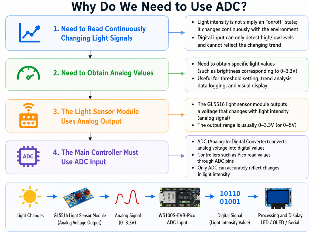
It should be noted that not any GPIO can be used for the ADC input of this board. The ADC function corresponds to specific GPIOs, so in the subsequent pin assignment, the analog output of the photosensitive module must be connected to a pin that supports ADC, instead of arbitrarily selecting a regular GPIO.
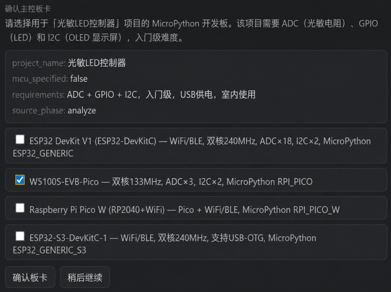
After analyzing the requirements, Blockless first extracts the hardware capabilities required for this project: ADC for reading the signal of the photosensitive module, GPIO for controlling the LED, and I2C for connecting the OLED; the project is powered via USB and used indoors.
Since no specific main controller is specified in the requirements, the page displays mcu_specified: false. Therefore, Blockless has provided multiple eligible development board candidates, including W5100S-EVB-Pico, ESP32 DevKit V1 and ESP32-S3-DevKitC-1.
Recommended Results
This case selects by default the W5100S-EVB-Pico. It is equipped with the ADC, GPIO and I2C interfaces required by this project and supports MicroPython, so it can realize photosensitive detection, LED control and OLED display functions.
Why do other boards still appear on the page?
Blockless does not provide a single fixed answer, but rather lists candidate boards that also meet the basic requirements. Both the ESP32 DevKit V1 and ESP32-S3-DevKitC-1 offer wireless communication capabilities, making them suitable for projects that require Wi-Fi, Bluetooth, remote control or data upload in the future.
How do users need to confirm
If your project only requires local light control and display functions, just like this case, you can confirm the W5100S-EVB-Pico; if your project has additional networking requirements, you should supplement requirements such as "Wi-Fi data upload required" or "mobile phone control required" in the requirement description, and then ask Blockless to re-analyze and select a suitable candidate board. Users do not need to memorize the parameters of each development board in advance, but should learn to inform Blockless of requirements such as "whether networking is required, which inputs and outputs are needed, and whether display is required", and then complete the confirmation based on the candidate solutions provided by the plugin.
What conditions should be considered for master control selection?
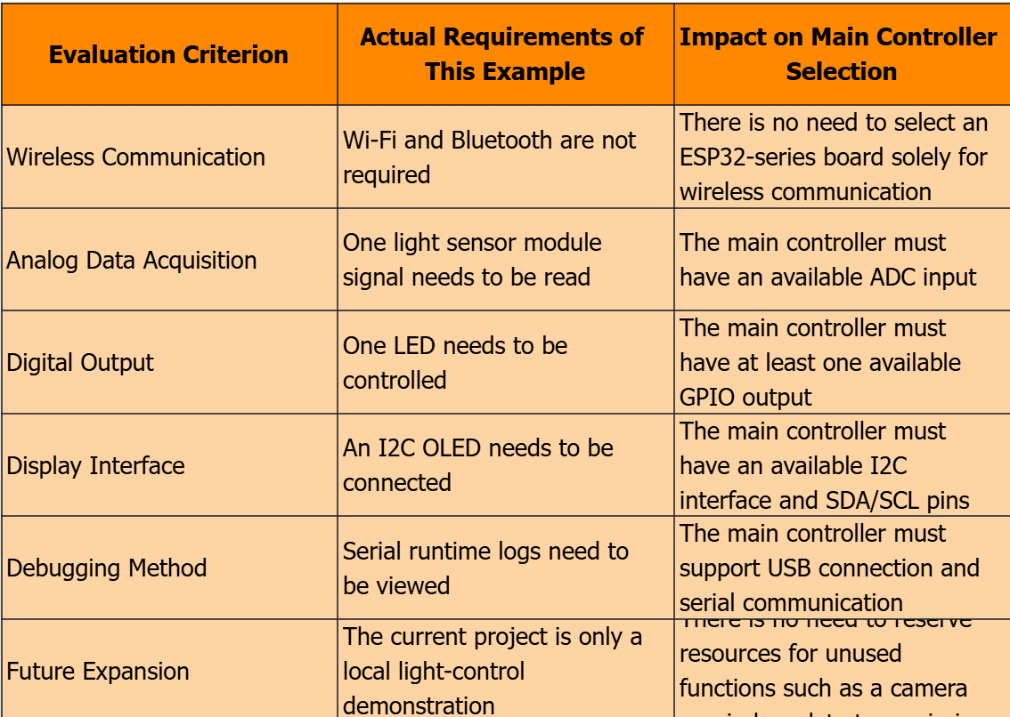
When selecting the main controller, it is recommended to make a judgment from the following six aspects first:
As can be seen from the above analysis, this case does not require a development board with the most functions, but a main controller that can stably provide ADC, GPIO, I2C and USB serial port capabilities.
Confirm the development board based on the existing hardware
If you already have a W5100S-EVB-Pico, you can explicitly specify this development board in your requirements, or manually select it via Browse boards. In this case, Blockless will generate the subsequent component, interface and pin schemes based on the specified board.
The user needs to confirm whether the name of the recommended or selected board matches the physical device in hand; if there is a discrepancy, they should go back to modify the development board instead of proceeding to generate the project.
Identify required components based on functions
After the case inputs requirements such as "read ambient light, automatically control LED, OLED display status", Blockless identifies the GL5516 photosensitive module, piranha LED and SSD1306 OLED.
Verify whether the recommendation results are in line with the actual situation
Before confirming the device, the user should check whether the recommended module matches the hardware in hand. For example, verify that the names of the photosensitive module, LED and OLED are correct, and whether the OLED is the I2C version; if the actually used module is different, click to modify the device list or return to modify the requirements.
2.3 How Blockless Recommends Interfaces and Pins
After the development board and components are confirmed, Blockless will automatically generate an interface and pinout scheme based on the module type. Users do not need to manually assign pins from scratch, but they need to verify that the recommended scheme does not conflict with the actual modules and existing wiring.
Assign a display interface to the OLED
Blockless assigns the SDA and SCL pins of the OLED to GP4 and GP5 respectively, and uses the I2C0 interface for communication. Meanwhile, it allocates a 3V3 power supply and GND pin to the OLED. Users need to confirm that the OLED they have is the I2C version, and connect the SDA, SCL, power and ground wires according to the instructions on the Wiring page.
Assign an input interface to the photosensitive module
Blockless assigns the AO pin of the GL5516 photosensitive module to GP26 to read ambient light changes. Users need to confirm that the AO analog output terminal of the module is actually used instead of other pins.
Assign control pins for the LED
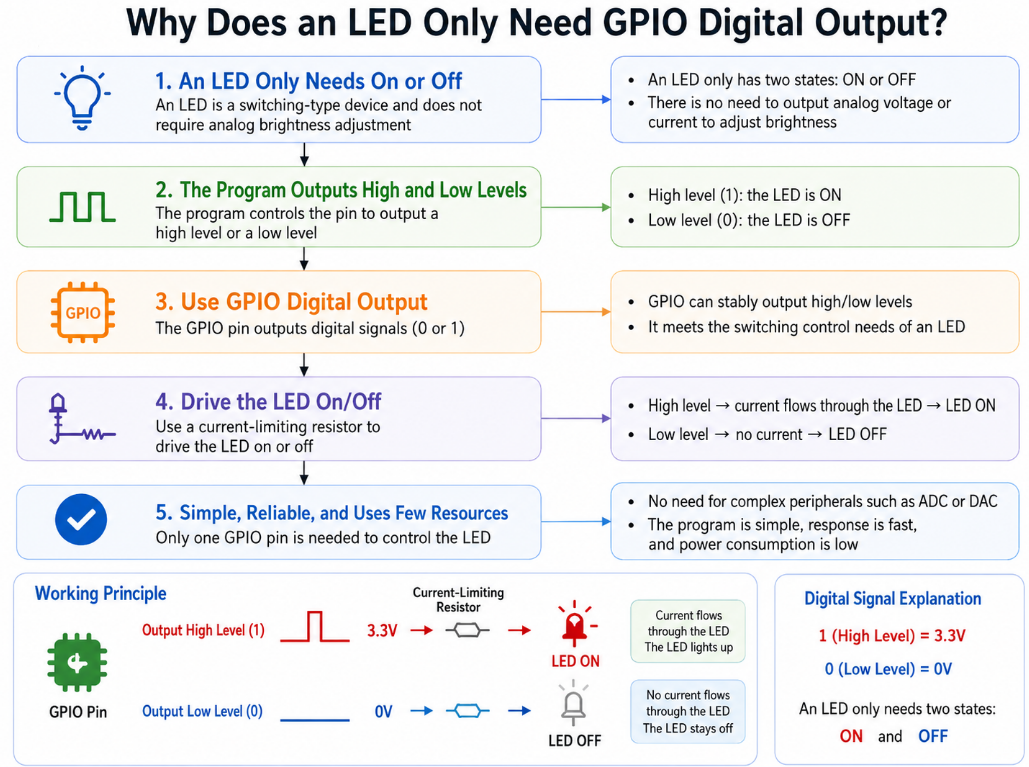
Blockless assigns the positive electrode of the Piranha LED to GP15, and notes that a 220 Ω current-limiting resistor needs to be connected in series; the negative electrode of the LED is connected to GND. Users shall complete the wiring in accordance with the recommended scheme and confirm that the positive and negative directions of the LED are correct.
Confirm whether there is an existing hardware conflict
If other modules are also connected to the project, check whether these modules have already used GP4, GP5, GP15 or GP26. In case of a conflict, you can either return to Blockless to modify the relevant pins, or supplement the information of existing modules and interfaces in the requirements before regenerating the solution.
For first-time users, the most important thing is to complete the wiring according to the recommended results; for users who already have other hardware, the most important thing is to confirm that the pins automatically assigned by the plug-in are not occupied. After the confirmation is completed, you can proceed to generate the project.
2.4 How to re-obtain the solution after requirement changes
The light-controlled LED is merely an example. In actual projects, users' requirements may increase, decrease, or change. In such cases, you should not directly reuse the development board, components, and pins from this example. Instead, you should modify the requirement description and then let Blockless re-analyze and generate a new solution.
Add network connectivity feature
If you want to upload data to the server or control the device via mobile phone or web page, you should specify "Wi-Fi network connection required", "data upload required" or "remote control required" in the requirements. Blockless will re-recommend the development board and project solution based on the new communication requirements.
Add new sensors or actuators
If you need to add temperature and humidity sensors, buzzers, relays or more LEDs, you should supplement the newly added modules and their functions in the requirements. For example, you can write "add temperature and humidity detection, and trigger the buzzer alarm when the temperature is too high". Blockless will re-identify the devices and update the interfaces and pin assignments accordingly.
Replace existing hardware
If the development board, OLED, or sensor you have is different from the one used in this case, please specify the actual model and interface type in your requirements. For example, when using a different development board, do not directly apply the pin configuration of the W5100S-EVB-Pico; instead, reconfirm the wiring information recommended by Blockless.
Modify the control logic
If the project is modified from "turn on the LED when the environment darkens" to "turn on the LED when the environment brightens", or additional functions such as timing control and alarm prompt are added, the requirement description shall also be directly modified accordingly. Blockless will update the generated code logic based on this.
When using Blockless, users do not need to master all hardware solutions in advance, but they need to develop a habit: re-describe the requirements, re-confirm the recommended solution, and re-check the wiring information after the requirements change. Only in this way can we avoid directly applying the device and pin schemes of old projects to new projects.
So far, we have learned how Blockless recommends development boards, components, interfaces and pins based on different user needs. The next chapter will take the light-controlled LED project as an example to demonstrate how to create and generate a project in Blockless.
3. Create a Light-controlled LED Project with Blockless
After completing hardware selection, interface verification and pin planning, the next step is to create a project in Blockless. When creating the project, users should not simply enter "make a light-controlled lamp", but clearly describe the main controller, input module, output module, display requirements and operation logic.
3.1 Start the workflow and select the Beginner mode
In the Activity page of Blockless, first select the Beginner mode, and confirm that the target development board is W5100S-EVB-Pico. Then fill in the project requirements in the requirement input box.
Select Beginner mode
In the project mode area, select Beginner. This mode is suitable for users who are creating a hardware project for the first time, and Blockless will recommend development boards, components, interfaces and pin solutions based on the requirements you input subsequently.
When to Use Beginner Mode
This case uses the Beginner mode, as the goal is to quickly complete the light-controlled LED project, with the initial solution automatically generated by Blockless. Users only need to confirm on the subsequent page whether the recommended result matches the actual hardware.
When to switch to Custom mode
If users already clearly know the development boards, modules, interfaces or pins they need to use and want to manually adjust the project configuration, they can select the Custom mode. For users who are using Blockless for the first time, it is recommended to complete the entire process of the Beginner mode first.
The requirement description should not be overly simplistic. For instance, if you only input "make a light-controlled LED", Blockless cannot determine which main controller to use, whether an OLED is required, whether the sensor should use analog output or digital output, nor can it know whether serial port logging is needed.
Conversely, if the user only knows the functional objectives and has not yet identified specific modules, they can first describe the function, for example, "detect ambient light, turn on the LED when the environment darkens, and display the status", and then let Blockless recommend candidate components and development boards. However, before confirming the solution, manual verification against the hardware actually purchased or already in possession is still required.
3.2 Confirm the device, development board and pin configuration
Click Generate, and Blockless will analyze your requirements and provide corresponding solutions for components, development boards, interfaces and pins in sequence. The key here is not to quickly click "Confirm", but to check whether the plugin's understanding is consistent with the solution determined in Chapter 2.
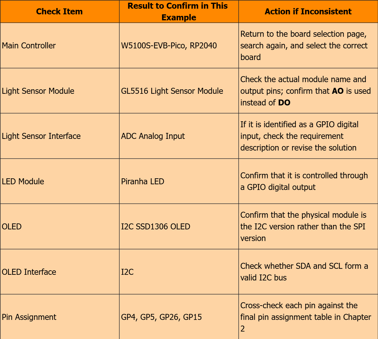
The following contents shall be focused on for verification in this case:
Check Item
Result to Confirm in This Example
Action if Inconsistent
Main Controller
W5100S-EVB-Pico, RP2040
Return to the board selection page, search again, and select the correct board
Light Sensor Module
GL5516 Light Sensor Module
Check the actual module name and output pins; confirm that AO is used instead of DO
Light Sensor Interface
ADC Analog Input
If it is identified as a GPIO digital input, check the requirement description or revise the solution
LED Module
Piranha LED
Confirm that it is controlled through a GPIO digital output
OLED
I2C SSD1306 OLED
Confirm that the physical module is the I2C version rather than the SPI version
OLED Interface
I2C
Check whether SDA and SCL form a valid I2C bus
Pin Assignment
GP4, GP5, GP26, GP15
Cross-check each pin against the final pin assignment table in Chapter 2
Blockless has identified the GL5516 photosensitive module, piranha LED and OLED display, and provided interface recommendations of ADC, GPIO and I2C for them respectively.
Manual confirmation is required at this point: GL5516 uses the ADC analog interface, the piranha LED uses GPIO digital output, and the SSD1306 OLED uses the I2C interface. If the identification result does not match the actual module, you should click "Modify Device List" or return to the requirement input page to revise the description, instead of proceeding to generate an incorrect project.
The scheme displayed on the pin confirmation page is consistent with that in Chapter 2:
OLED SDA connects to GP4;
OLED SCL is connected to GP5;
GL5516 AO is connected to GP26, namely ADC0;
The positive electrode of the piranha LED is connected to GP15, with a 220 Ω current-limiting resistor connected in series;
OLED and GL5516 are powered by 3V3;
All modules are connected to the common GND.
During confirmation, check each item one by one instead of only verifying a single pin. For example, even if the GL5516 is correctly identified, it must be confirmed that its AO is connected to GP26; even if the OLED is displayed as I2C, it must be confirmed that SDA and SCL are connected to GP4 and GP5 respectively.
3.3 Generate the project and check the generation results
After the device, development board, interface and pin scheme are all confirmed to be correct, click Confirm Pin Scheme and Continue, then follow the prompts on the Blockless page to complete the subsequent generation operations.
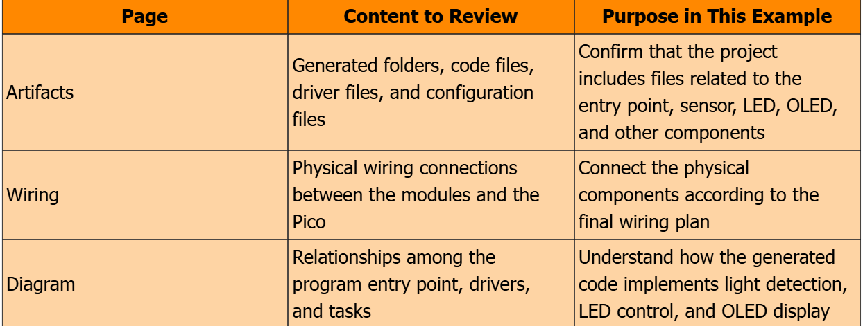
It should be noted that clicking Generate or confirming the solution only indicates that Blockless has started generating the project, and does not mean that the project has completed the real machine verification. After the generation is completed, it is still necessary to check the project files, wiring information, program architecture and deployment results.
After the project is generated, the following three pages shall be focused on for review:
Page
Content to Review
Purpose in This Example
Artifacts
Generated folders, code files, driver files, and configuration files
Confirm that the project includes files related to the entry point, sensor, LED, OLED, and other components
Wiring
Physical wiring connections between the modules and the Pico
Connect the physical components according to the final wiring plan
Diagram
Relationships among the program entry point, drivers, and tasks
Understand how the generated code implements light detection, LED control, and OLED display
So far, Blockless has generated the light-controlled LED project based on the confirmed hardware solution. The next step will be code generation analysis, which will explain how each module jointly completes light detection, threshold judgment, LED control, OLED display and serial port output in combination with the project directory, key files and program logic.
4. Prototype Testing and Results
After completing the Blockless project generation, hardware wiring and deployment, it is necessary to verify whether the system works as required through physical phenomena, OLED display and serial port logs. The test is not only to observe whether the LED is lit, but also to confirm whether the sensor input, program judgment, LED output and OLED display are consistent with each other.
4.1 Pre-test Check
Prior to starting the test, the following checks shall be completed first:
W5100S-EVB-Pico has been connected to the computer via a USB data cable;
The GL5516 photosensitive module, Piranha LED and SSD1306 OLED have been wired in accordance with the Wiring page;
The OLED, photosensitive module and Pico have been properly connected to 3.3 V and GND;
The AO of the photosensitive module has been connected to GP26;
The SDA and SCL of the OLED have been connected to GP4 and GP5 respectively;
The positive electrode of the LED has been connected to GP15 via a 220 Ω current-limiting resistor, and the negative electrode is connected to GND;
The project has been deployed to the development board, and the serial port page can be opened properly.
4.2 Functional Test under Bright and Dark Environments
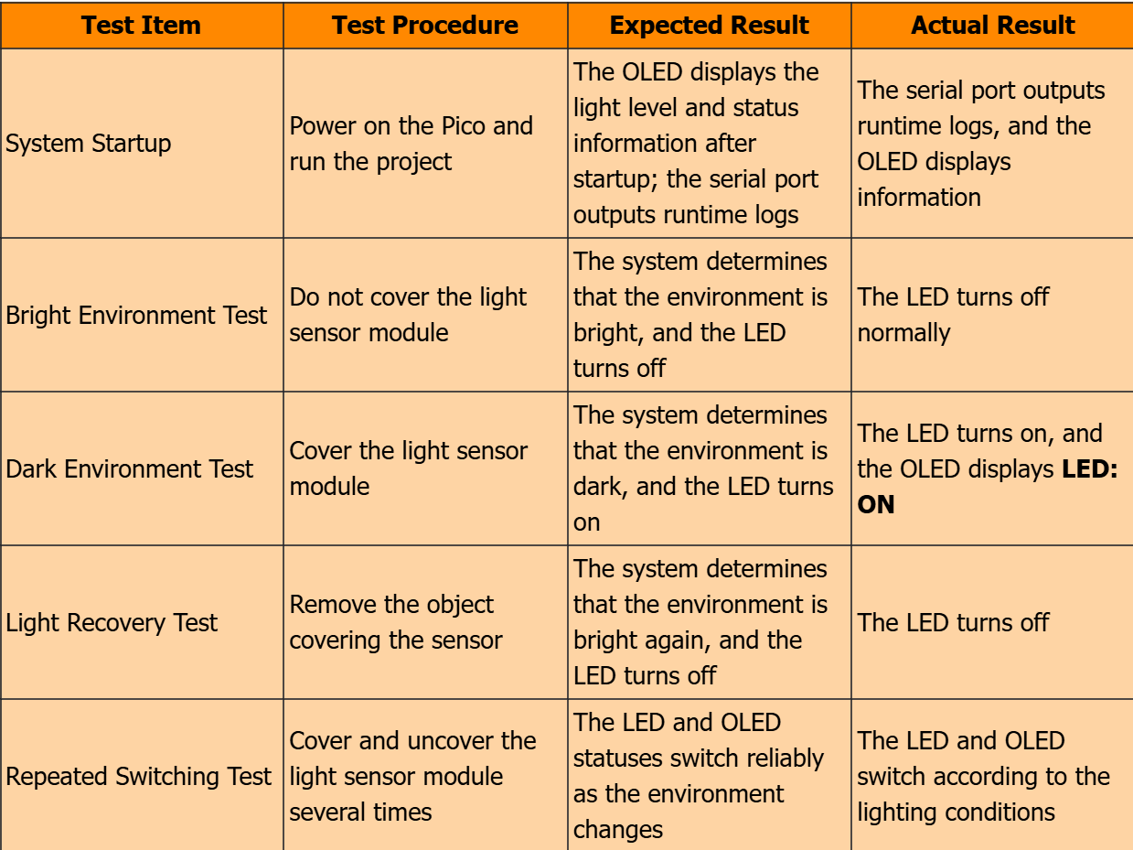
The core testing method of this project is to change the ambient light received by the GL5516 photosensitive module, and observe the changes of the LED, OLED and serial port.
During testing, you can use your palm or an opaque object to cover the photosensitive module to reduce the light intensity received by the module; then remove the covering to allow the module to receive ambient light again.
The test items for this case are as follows.
Test Item
Test Procedure
Expected Result
Actual Result
System Startup
Power on the Pico and run the project
The OLED displays the light level and status information after startup; the serial port outputs runtime logs
The serial port outputs runtime logs, and the OLED displays information
Bright Environment Test
Do not cover the light sensor module
The system determines that the environment is bright, and the LED turns off
The LED turns off normally
Dark Environment Test
Cover the light sensor module
The system determines that the environment is dark, and the LED turns on
The LED turns on, and the OLED displays LED: ON
Light Recovery Test
Remove the object covering the sensor
The system determines that the environment is bright again, and the LED turns off
The LED turns off
Repeated Switching Test
Cover and uncover the light sensor module several times
The LED and OLED statuses switch reliably as the environment changes
The LED and OLED switch according to the lighting conditions
During the test, it can be observed that when the GL5516 photosensitive module is covered, the ambient light intensity decreases, the system turns on the piranha LED, and the OLED displays LED : ON. This indicates that the input signal of the photosensitive module has been read by the Pico, the program has completed the threshold judgment, and the LED output is controlled via GP15.
5. General Model Selection Process and Scheme Expansion
This case uses a light-controlled LED system to demonstrate the project creation process of Blockless, and more importantly, it forms a set of methods that can be migrated to other embedded projects.
5.1 General Process from Requirements to Prototype Verification
When faced with a new embedded requirement, you can conduct the analysis by following the steps below:
Define the project goal
↓
Break down the input, processing, output, and display functions
↓
Determine the interfaces and communication capabilities required by the main controller
↓
Select the main controller, sensors, actuators, and display module
↓
Determine whether each module uses ADC, GPIO, I2C, SPI, or UART
↓
Assign pins and check for conflicts
↓
Enter the complete requirements in Blockless and confirm the solution
↓
Generate the project, complete the wiring, deploy, and test
The core of this process is: clarify the requirements first, then select the hardware; check the interfaces first, then assign the pins; confirm the solution first, then generate the code.
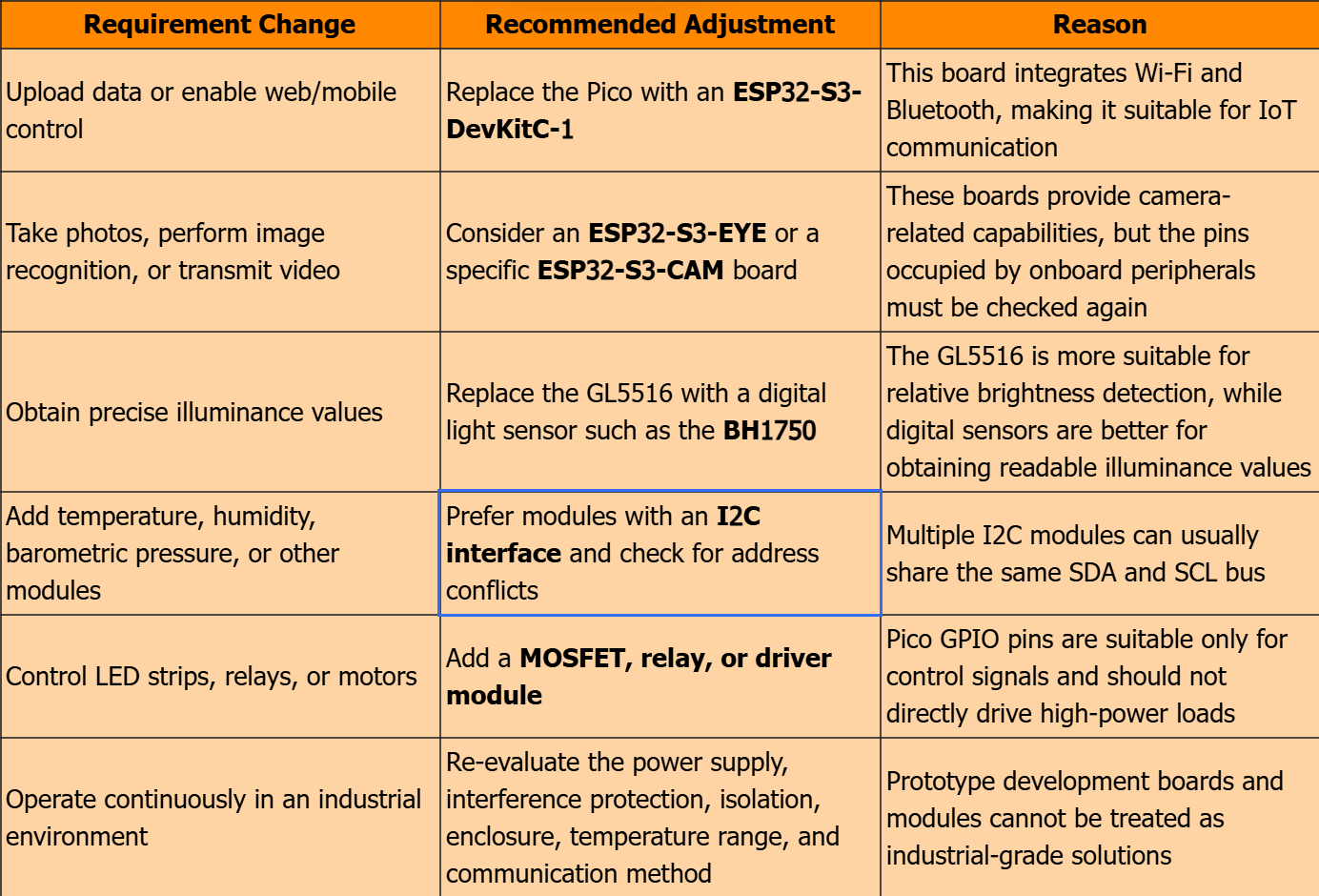
5.2 How to adjust the hardware solution when requirements change
For the same "light-controlled LED" project, the hardware selection should also be adjusted accordingly after the requirements change.
Requirement Change
Recommended Adjustment
Reason
Upload data or enable web/mobile control
Replace the Pico with an ESP32-S3-DevKitC-1
This board integrates Wi-Fi and Bluetooth, making it suitable for IoT communication
Take photos, perform image recognition, or transmit video
Consider an ESP32-S3-EYE or a specific ESP32-S3-CAM board
These boards provide camera-related capabilities, but the pins occupied by onboard peripherals must be checked again
Obtain precise illuminance values
Replace the GL5516 with a digital light sensor such as the BH1750
The GL5516 is more suitable for relative brightness detection, while digital sensors are better for obtaining readable illuminance values
Add temperature, humidity, barometric pressure, or other modules
Prefer modules with an I2C interface and check for address conflicts
Multiple I2C modules can usually share the same SDA and SCL bus
Control LED strips, relays, or motors
Add a MOSFET, relay, or driver module
Pico GPIO pins are suitable only for control signals and should not directly drive high-power loads
Operate continuously in an industrial environment
Re-evaluate the power supply, interference protection, isolation, enclosure, temperature range, and communication method
Prototype development boards and modules cannot be treated as industrial-grade solutions
5.3 Items Requiring Manual Confirmation When Using Blockless
Blockless can quickly generate development boards, components, interfaces, pins and code solutions based on natural language requirements
But engineers still need to take responsibility for the actual hardware.
When using Blockless, manual confirmation shall be focused on the following key points:
Whether the recommended development board meets the networking, performance and interface requirements of the project;
Check whether the recommended device is consistent with the actual module in hand;
whether the module actually uses analog output, digital output, I2C or SPI;
Whether the pin configuration complies with interface specifications such as ADC, GPIO, and I2C;
Whether the module power supply voltage, common ground and load driving method are safe;
Whether the generated code is consistent with the physical wiring and the final requirements;
Can the test results prove that the project has been truly completed?
5.4 Project Summary
Based on the W5100S-EVB-Pico, GL5516 photosensitive module, piranha LED module and SSD1306 OLED, this case realizes the functions of automatically turning on the LED when the environment darkens, automatically turning off the LED when the environment brightens, and displaying the system status on the OLED and the serial port.
More importantly, this case demonstrates the complete process of an embedded project, covering requirement analysis, hardware selection, interface judgment, pin allocation, Blockless project generation, and real-machine verification. When dealing with different projects in the future, readers can first re-analyze the requirements following the method in this case, then select appropriate main controllers, modules and interfaces, instead of directly copying the existing wiring schemes.