



Practical Application of One‑Wire Communication: Full Breakdown of DHT11 Device Principles, Protocol
This paper introduces DHT11 single-wire communication timing, 40-bit data format, MicroPython driver with pulse capture and checksum, and Pico hardware test, pl
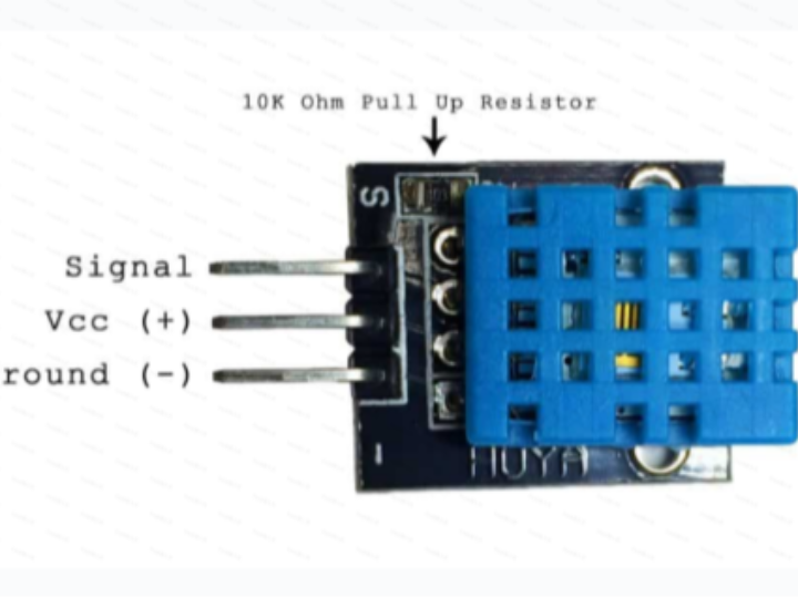
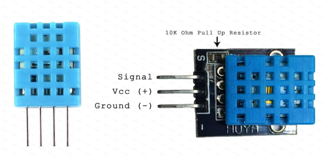
The DHT11 digital temperature and humidity sensor is a temperature and humidity composite sensor with calibrated digital signal output. It uses dedicated digital module acquisition technology and temperature/humidity sensing technology to ensure high reliability and excellent long-term stability. The sensor includes a capacitive humidity sensing element and an NTC temperature measuring element, connected to a high-performance 8-bit microcontroller.
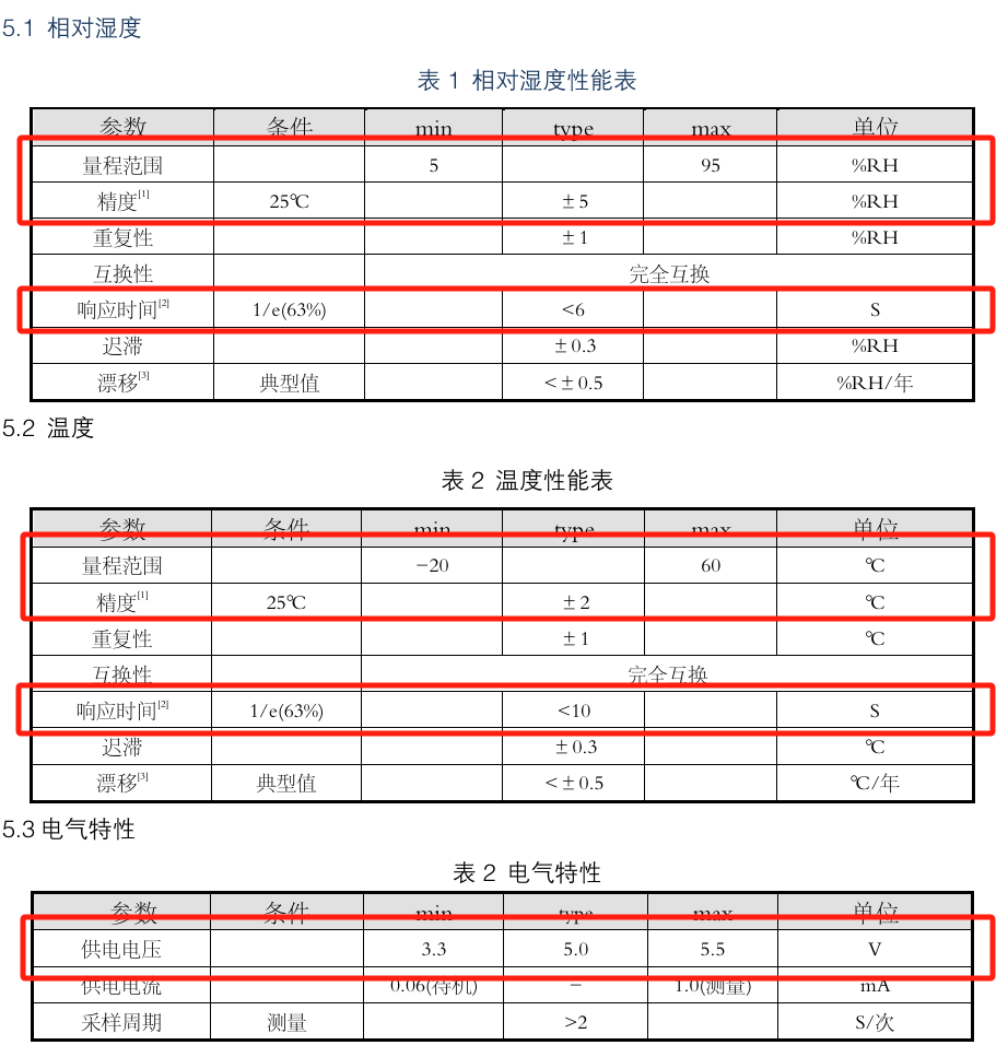
The main parameters are as follows, with the key parameters marked in red:
1. DHT11 Sensor Communication Protocol Analysis
1.1 Data Format of 1-Wire Transmission
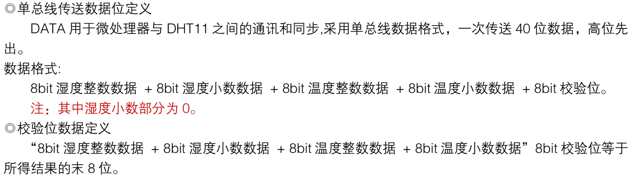
The 1-Wire data format is defined as follows:
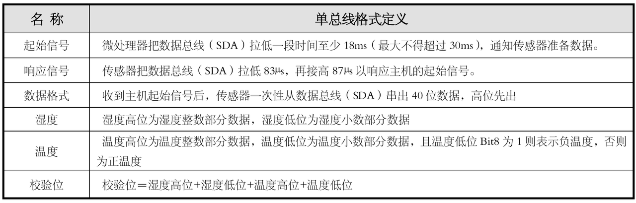
Among them, the data format part is humidity data + temperature data + data checksum. The integer and decimal parts of the temperature and humidity data each occupy 8 bits. In the transmitted data, the MSB comes first, in big-endian order. The checksum is the 8th bit of the sum of the temperature and humidity data:
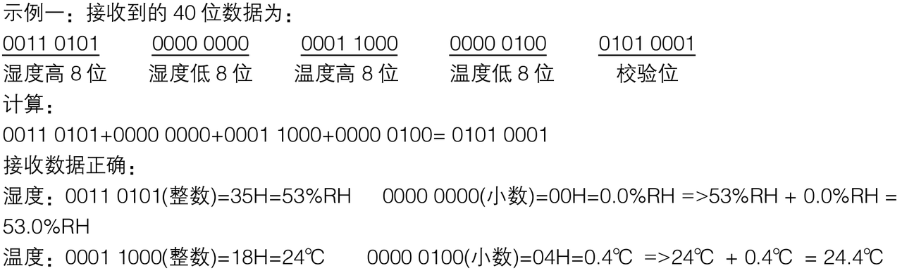
When the checksum data is incorrect, it means an error occurred in data reception. The data obtained this time should be discarded and the next data received.
Note that the DHT11 sensor temperature measurement range is -20°C to 60°C. When the transmitted temperature data is negative, the highest bit of the decimal part of the temperature data, i.e., the high bit of the low 8 bits of the data, is set to 1:

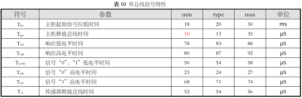
1.2 1-Wire Communication Timing and Electrical Characteristics
After the microcontroller sends a start signal, the DHT11 switches from low-power mode to high-speed mode. After the host's start signal ends, the DHT11 sends a response signal, sends 40 bits of data, and triggers one data collection. The signal transmission is shown in the figure:

1.3 Steps for the Microcontroller to Read the DHT11 Sensor
Power-on delay of the sensor; the idle state remains at high level:

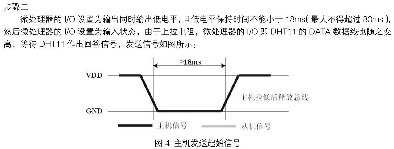
The host calls the slave and waits for a response:
The slave responds, and the host IO port switches from output to input state, waiting for data reception:
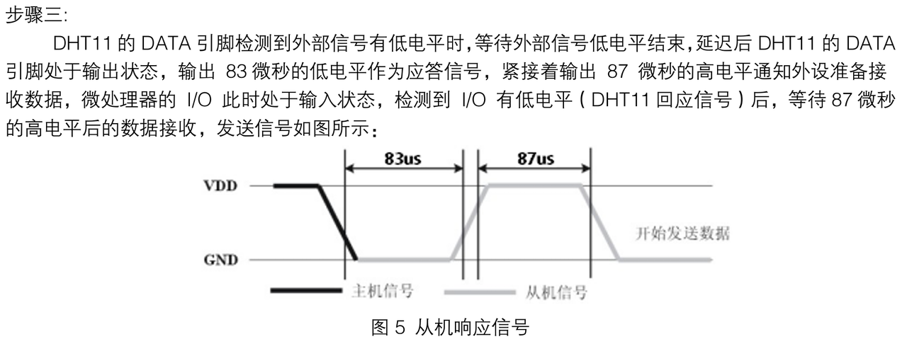
The host receives data bit by bit:

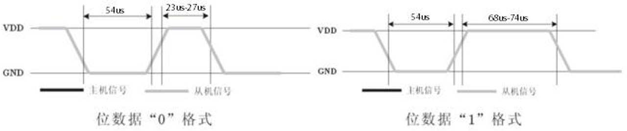
The slave releases the bus and ends communication:

2. DHT11 Sensor Driver Code
Here, let's first briefly describe our method for reading the DHT11 sensor temperature and humidity data:
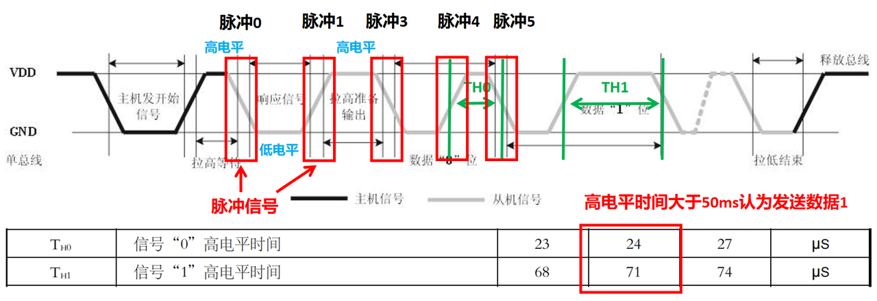
After the host sends the start signal, the host data pin switches to input state and releases the bus. From then on, all level state changes on the bus are controlled by the slave. We use the host data pin to read the high/low level changes. Here, we define one high/low level change as one pulse, and record how long each pulse signal maintains its level after the level changes. By comparing the high-level holding time with TH0 and TH1, we determine whether the data bit sent by the DHT11 sensor is 0 or 1. 40 bits of data correspond to 80 data pulses. Starting from the fourth pulse (inclusive), the high-level holding time after every two pulses can be used as a flag to determine whether the data bit sent by the DHT11 sensor is 0 or 1.
Here, we first define two custom exception classes to throw exceptions when errors occur during DHT11 data reading:
# Custom exception class: checksum error
class InvalidChecksum(Exception):
"""
InvalidChecksum exception class, used to indicate an exception caused by a checksum error.
This exception is thrown when data verification fails, usually used to detect data integrity, such as CRC check errors or other checksum errors.
Attributes:
message (str): exception message, describing the reason for the verification failure.
"""
pass
# Custom exception class: data pulse count error
class InvalidPulseCount(Exception):
"""
InvalidPulseCount exception class, used to indicate an exception caused by an incorrect data pulse count.
This exception is usually thrown when the number of pulse signals does not match expectations, for example, an abnormal pulse count during signal decoding.
Attributes:
message (str): exception message, describing the reason for the pulse count error.
"""
passThen a class named DHT11 is defined for interacting with the DHT11 temperature and humidity sensor, defining some class-related variables. In the class constructor, some instance variables are initialized, including the data bus pin connected to the DHT11 sensor, the time of the last data read, and variables for storing temperature and humidity data.
# DHT11 temperature and humidity sensor class
class DHT11:
"""
DHT11 class, used to read DHT11 temperature and humidity sensor data through the GPIO interface.
This class encapsulates communication with the DHT11 sensor and provides methods for obtaining temperature and humidity.
When using this class, a GPIO pin needs to be provided for communication with the sensor, and the sensor data can be read.
Attributes:
pin (int): the GPIO number connected to the DHT11 data pin.
_last_measure (int): the time of the last data read, in microseconds.
_temperature (float): temperature data, in degrees Celsius.
_humidity (float): humidity data, in percentage.
Methods:
measure(): read DHT11 sensor data and update the temperature and humidity values.
humidity(): get the currently measured humidity value (unit: %RH).
temperature(): get the currently measured temperature value (unit: ℃).
"""
# Class-related variables of the DHT11 sensor class:
# Maximum count value for unchanged pin level
MAX_UNCHANGED = const(100)
# Interval between two data reads, in microseconds, 200000 microseconds, i.e., 200 milliseconds
MIN_INTERVAL_US = const(200000)
# High-level holding time, in microseconds, 50 microseconds
# When DHT11 sends data 1, the high-level holding time is greater than 50us (typical value is 71us)
# When DHT11 sends data 0, the high-level holding time is less than 50us (typical value is 24us)
HIGH_LEVEL = const(50)
# Expected number of pulses, i.e., the 4 pulses generated by the slave response after initialization + the high/low level pulses corresponding to the 40 data bits output by DHT11
EXPECTED_PULSES = const(84)
def __init__(self, pin: int):
"""
Initialize the DHT11 sensor.
Args:
pin (int): the GPIO number connected to the DHT11 data pin.
Returns:
None
"""
# Initialize instance variables; all are private variables inaccessible from outside
self._pin = pin
# Record the time of the last data read
self._last_measure = time.ticks_us()
self._temperature = -1
self._humidity = -1Then a method named measure is defined for reading temperature and humidity data. First, it checks whether enough time has passed for the next measurement; if not, it returns directly. Then it sends an initialization signal to the slave and waits for the slave's response. Next, it captures the duration sequence of the high/low level pulses sent by the slave and converts it into a 5-byte array. Finally, it calculates the checksum and updates the temperature and humidity data.
def measure(self) -> None:
"""
Read DHT11 sensor data and update the temperature and humidity values.
Args:
None
Raises:
InvalidChecksum: if the data checksum is incorrect.
InvalidPulseCount: if the data pulse count is incorrect.
"""
# Get the current time
current_ticks = time.ticks_us()
# Check whether enough time has passed for the next measurement; if not, return directly
if time.ticks_diff(current_ticks, self._last_measure) < DHT11.MIN_INTERVAL_US and (
self._temperature > -1 or self._humidity > -1
):
return
# Send the initialization signal to call the slave
self._send_init_signal()
# After the slave responds and sends data, the host pin switches to input mode
# Get the duration sequence of the high/low level pulses sent by the slave
pulses = self._capture_pulses()
# Determine whether the data sent is 0 or 1 according to the high-level holding time of each data bit sent by DHT11
# Convert the 40-bit data sequence into a 5-byte array output
buffer = self._convert_pulses_to_buffer(pulses)
# Calculate the checksum; if the checksum is incorrect, throw an InvalidChecksum exception
self._verify_checksum(buffer)
# Calculate the humidity data, i.e., humidity integer part + decimal part
self._humidity = buffer[0] + buffer[1] / 10
# Calculate the temperature data, i.e., temperature integer part + decimal part
self._temperature = buffer[2] + buffer[3] / 10
# Update the time of the last data read to the current time
self._last_measure = time.ticks_us()The method execution flow is:
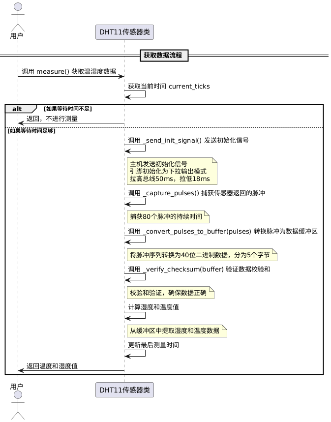
The measure method mainly calls the following methods:
_send_init_signal method: send the initialization signal to call the slave
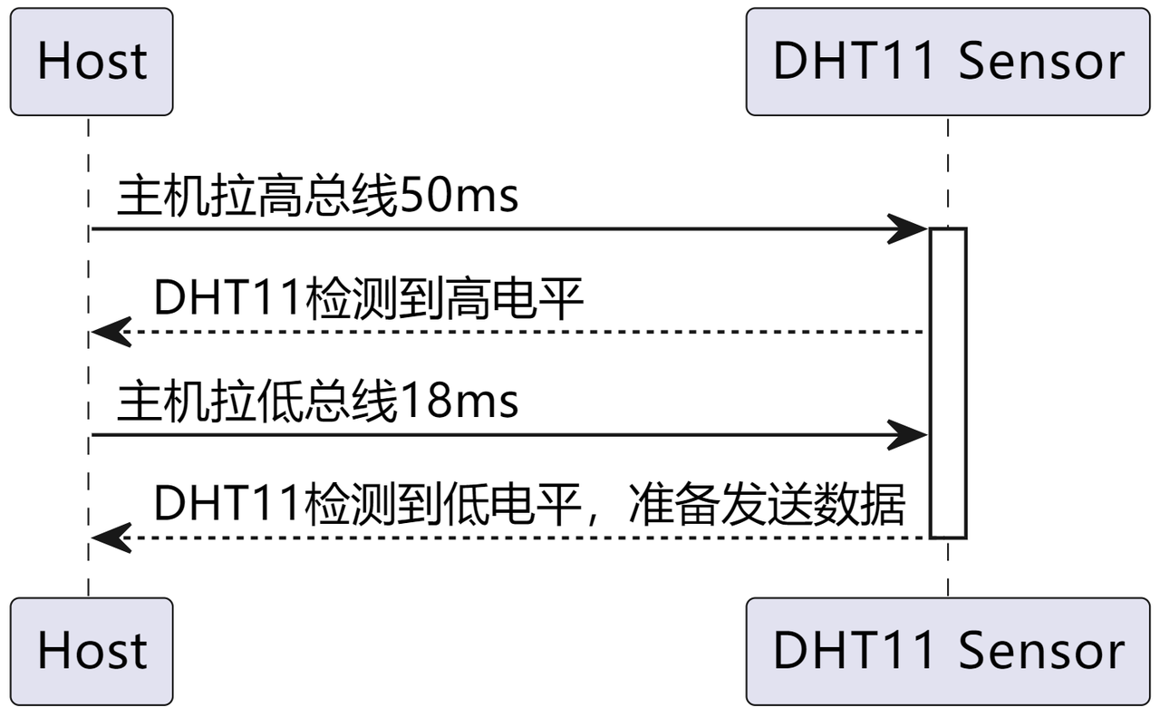
# Send the initialization signal
def _send_init_signal(self) -> None:
"""
Send the initialization signal to call the slave.
Args:
None
Returns:
None
"""
# The host pin is in pull-down output mode
self._pin.init(Pin.OUT, Pin.PULL_DOWN)
# The host pulls the bus high for 50ms; at this time, the DHT11 pin is in input state to detect external signals
self._pin.value(1)
time.sleep_ms(50)
# The host pulls the bus low for 18ms, sending the initialization signal to call the slave
self._pin.value(0)
time.sleep_ms(18)_capture_pulses method: capture the duration sequence of the 80 pulses returned by the DHT11 sensor
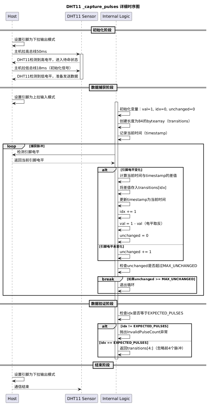
# Capture the duration sequence of the 80 pulses returned by the DHT11 sensor
# Use the @micropython.native decorator to compile the method into machine code to improve running efficiency
.native
def _capture_pulses(self) -> bytearray:
"""
Capture the duration sequence of the 80 pulses returned by the DHT11 sensor.
Returns:
bytearray: the sequence of pulse high/low level durations.
Raises:
InvalidPulseCount: if the number of captured pulses is incorrect.
"""
# Convert the pin to pull-up input mode
pin = self._pin
pin.init(Pin.IN, Pin.PULL_UP)
# Temporary variable recording the pin level
val = 1
# Counter variable for high/low level pulses
idx = 0
# Create an empty array to store 84 pulses
# Among them:
# The first 4 pulses are generated by the slave response
# The last 80 pulses are data bits
transitions = bytearray(DHT11.EXPECTED_PULSES)
# Variable recording the number of times the pin level remains unchanged
unchanged = 0
# Record the current time
timestamp = time.ticks_us()
# Exit the loop when the number of times the pin level remains unchanged exceeds DHT11.MAX_UNCHANGED
while unchanged < DHT11.MAX_UNCHANGED:
# Check whether the pin level has changed
if val != pin.value():
# When idx is greater than DHT11.EXPECTED_PULSES, it means the number of captured pulses is incorrect
# Throw an InvalidPulseCount exception
if idx >= DHT11.EXPECTED_PULSES:
raise InvalidPulseCount(
"Got more than {} pulses".format(DHT11.EXPECTED_PULSES)
)
now = time.ticks_us()
# The transitions binary sequence records the duration of the pulse sequence
transitions[idx] = now - timestamp
timestamp = now
# idx increments
idx += 1
# val is equivalent to an inversion operation
val = 1 - val
unchanged = 0
else:
# The pin level has not changed; increase the count of unchanged pin level by 1
unchanged += 1
# After data reception is complete, the host switches to pull-down output mode to end communication
pin.init(Pin.OUT, Pin.PULL_DOWN)
# Check whether the number of received pulses is the expected number of pulses
if idx != DHT11.EXPECTED_PULSES:
# If not, throw an InvalidPulseCount exception
raise InvalidPulseCount(
"Expected {} but got {} pulses".format(DHT11.EXPECTED_PULSES, idx)
)
# Return the last 80 bytes of the captured pulse duration sequence
# Ignore the first 4 bytes, i.e., the 4 pulses generated by the slave response
return transitions[4:]_convert_pulses_to_buffer method: convert the captured pulse sequence into a 5-byte array
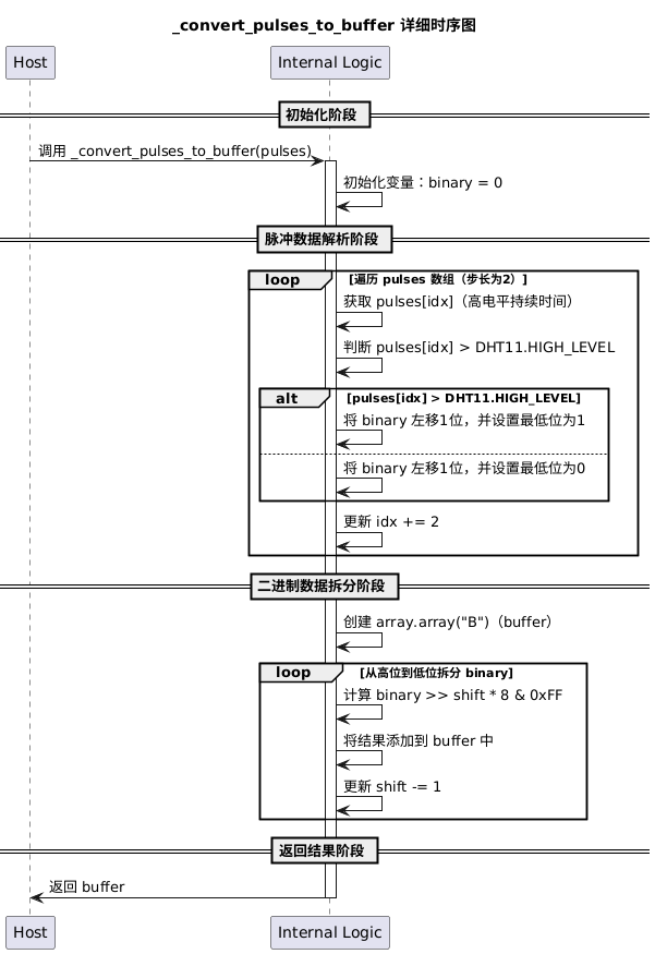
# Use the @micropython.native decorator to compile the method into machine code to improve running efficiency
.native
def _convert_pulses_to_buffer(self, pulses: bytearray) -> array.array:
"""
Convert the captured pulse sequence into a 5-byte array.
Args:
pulses (bytearray): the binary array corresponding to the pulse sequence.
Returns:
array.array: 5-byte array, i.e., humidity data integer value, humidity data decimal value, temperature data integer value, temperature data decimal value, checksum.
"""
# Convert the last 80 bytes of the captured pulse duration sequence into corresponding binary data
binary = 0
# Determine whether the sent binary data is 0 or 1 according to the high-level holding time
# When DHT11 sends data 1, the high-level holding time is greater than 50us (typical value is 71us)
# When DHT11 sends data 0, the high-level holding time is less than 50us (typical value is 24us)
# range(0, len(pulses), 2) means starting from index 0, incrementing by 2 each time until reaching the length of the pulses list
# This code traverses all elements at odd indexes in the pulses list
for idx in range(0, len(pulses), 2):
# Shift the current binary value left by 1 bit, and compare the element at the corresponding index in the pulses list with DHT11.HIGH_LEVEL:
# If it is greater than DHT11.HIGH_LEVEL, add 1 to binary
# Otherwise, add 0 to binary
# This process is equivalent to concatenating the binary data in the pulses list together to form a 40-bit binary number
binary = binary << 1 | int(pulses[idx] > DHT11.HIGH_LEVEL)
# Split the 40-bit binary number into 5 bytes and add them to the buffer array
# Create an array with elements of unsigned byte type
buffer = array.array("B")
# The shift variable represents the number of bits of the binary number to extract
# range(4, -1, -1) means starting from 4, decrementing by 1 each time until -1
# A reverse loop from 4 to 0 is used, which means extracting data from the highest bit to the lowest bit
for shift in range(4, -1, -1):
# Shift binary right by shift*8 bits, then AND with 0xFF to take the lowest 8 bits
# Get an integer between 0 and 255 and add it to the buffer list
buffer.append(binary >> shift * 8 & 0xFF)
return buffer_verify_checksum method: verify the checksum
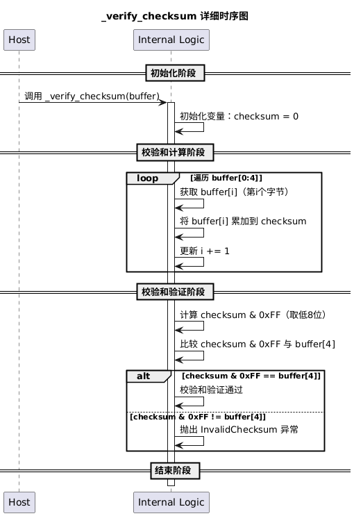
# Use the @micropython.native decorator to compile the method into machine code to improve running efficiency
@micropython.native
def _verify_checksum(self, buffer: array.array) -> None:
"""
Verify the checksum.
Args:
buffer (array.array): the array corresponding to the 40-bit data sent by DHT11.
Returns:
None
Raises:
InvalidChecksum: if the checksum verification fails.
"""
checksum = 0
for buf in buffer[0:4]:
# Accumulate the checksum
checksum += buf
# Compare the low 8 bits of the received data checksum with buffer[4], the checksum sent by the DHT11 slave
if checksum & 0xFF != buffer[4]:
# If they are not equal, throw an InvalidChecksum exception
raise InvalidChecksum()For obtaining the temperature and humidity data, we define two methods here, decorated with the @property decorator, so that we can call these methods like accessing object properties without explicitly calling them. These two methods actually call the measure() method to obtain data:
# Get humidity data
# @property is a decorator used to convert a method into a property accessor
@property
def humidity(self) -> float:
"""
Get the humidity data.
This method uses the @property decorator, so it can be called like accessing an object property without explicitly calling the method.
Args:
None
Returns:
float: the currently measured humidity value (unit: %RH).
Raises:
InvalidChecksum: if the data checksum is incorrect.
InvalidPulseCount: if the data pulse count is incorrect.
"""
self.measure()
return self._humidity
# Get temperature data
@property
def temperature(self) -> float:
"""
Get the temperature data.
This method uses the @property decorator, so it can be called like accessing an object property without explicitly calling the method.
Args:
None
Returns:
float: the currently measured temperature value (unit: ℃).
Raises:
InvalidChecksum: if the data checksum is incorrect.
InvalidPulseCount: if the data pulse count is incorrect.
"""
self.measure()
return self._temperature3. Application Experiment
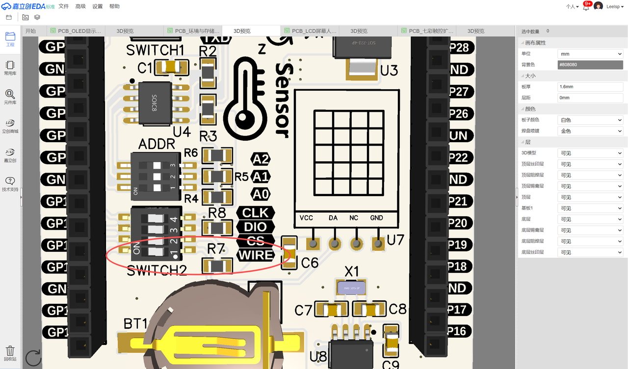
First, we need to insert the Fengya One Board - Environment and Storage Acquisition Board into the Fengya One Board - Universal Compatible Expansion Board, and turn on the WIRE option of the SWITCH2 DIP switch on the Fengya One Board - Environment and Storage Acquisition Board:
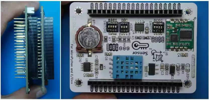
The pins used are shown in the following table:
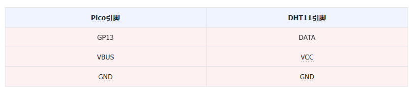
Here, we use GP13 to connect to the DHT11 data bus, and connect a 4.7K pull-up resistor to the data bus. It should be noted that:
When reading the temperature and humidity values, you need to read continuously 2 times to obtain real-time data; each value read is actually the result of the previous measurement
Reading the sensor at intervals greater than 2 seconds gives accurate data; continuous multiple reads are not recommended
Long-term exposure to sunlight or strong ultraviolet radiation will degrade sensor performance
Avoid placing the component in condensing, dry, or acidic gas environments for a long time
The relative humidity of gas is greatly affected by temperature; when measuring relative humidity at different times, the temperature should be kept similar
The following code can be found in the elegance-devkit v1\Demo\37 OneWire_DHT11 folder in our resource package.
In the main program section, we first declare two global variables for storing temperature and humidity data:
# ======================================== Global variables ============================================

# Humidity data
humidity = 0.0
# Temperature data
temperature = 0.0
In the initialization configuration, we instantiate the pin used for the data line:
# ======================================== Initialization configuration ==========================================


# Delay to wait for device initialization
time.sleep(3)
# Print debug information
print('FreakStudio : Using OneWire to read DHT11 sensor')

# Delay 1s to wait for the DHT11 sensor to complete power-on
time.sleep(1)
# Initialize the 1-Wire communication pin, pull-down output
DHT11_PIN = Pin(13, Pin.OUT, Pin.PULL_DOWN)
# Initialize the DHT11 instance
dht11 = DHT11(DHT11_PIN)
In the main program section, we periodically read the temperature and humidity data:
# ======================================== Main program ============================================

while True:
    # Read temperature and humidity data
    temperature = dht11.temperature
    humidity = dht11.humidity
    # Print the temperature and humidity data
    print("temperature: {}℃, humidity: {}%".format(temperature, humidity))
    # Wait 2 seconds
    utime.sleep(2)
After flashing the code to the Raspberry Pi Pico and opening the remote port, you can see the Raspberry Pi Pico outputs the following:
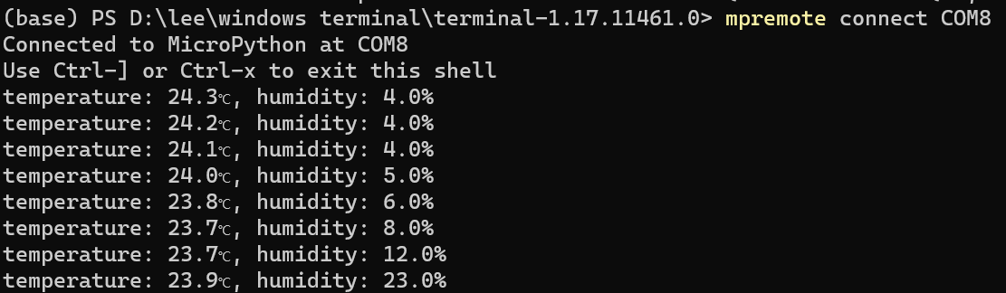
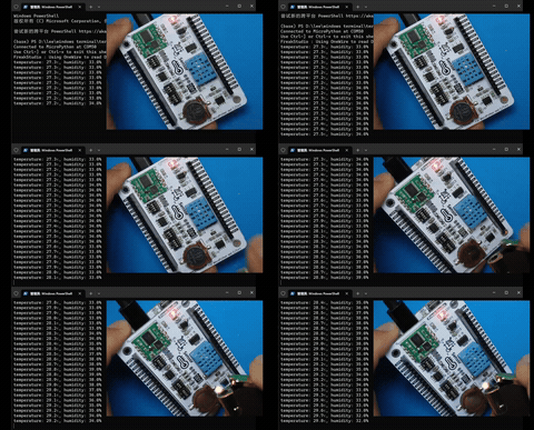
While the DHT11 sensor is running, we use a lighter to burn next to the sensor:
This content cannot be displayed outside Feishu documents for now
We can see that the DHT11 sensor temperature changes slightly and very slowly. In fact, the DHT11 sensor is not suitable for measuring absolute temperature and absolute humidity, but is suitable for measuring relative temperature and relative humidity. It has the following disadvantages:
Low accuracy: the accuracy of the DHT11 temperature and humidity sensor is not as good as some high-end sensors; its temperature accuracy is +2℃, and humidity accuracy is ±5%RH.
Long response time: the response time of the DHT11 temperature and humidity sensor is long, and it takes some time to output stable data, making it unsuitable for application scenarios with high real-time requirements.
Limited transmission distance: the transmission distance of the DHT11