PIO Quick Start: On‑Board LED Blink — Principles & Code Walkthrough
This example uses RP2040‑PIO in MicroPython to blink Pico’s onboard LED via state‑machine without CPU‑loop blocking.
COMPONENTS
PROJECT DESCRIPTION
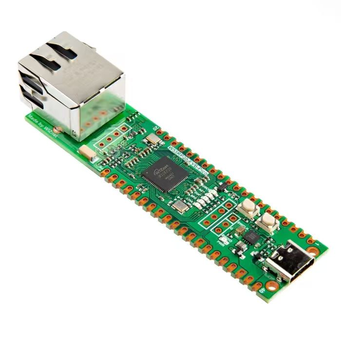
【Preliminary Note】The original hardware example in this article was written based on the RP2040. The actual hardware used in this hands-on demonstration features the W55RP20 as the main controller chip. The circuit logic and UF2 flashing operation principles are universally applicable, with only the main controller model differing. The original chip model mentioned in the circuit descriptions below is provided for reference purposes only.
PIO controls the on-board LED to blink
The following code can be found in the elegance-devkit v1\Demo\29 PIO_LED folder of the resource package we provide.
We first use PIO to control the onboard LED of the Pico to blink, and the sample code is as follows:
Importing Modules: First, the necessary modules are imported, including machine for handling hardware operations, time for processing time-related tasks, and the rp2 module, which is a specific function in MicroPython for the Raspberry Pi Pico RP2040 chip.
Function: Defines a function named blink, which is a PIO program used to control the blinking of the LED. This function uses the @rp2. asm_pio decorator to define the PIO program, and sets the initial state, frequency and pins of the program.
Initialization configuration: a finite-state machine object named sm is created, which loads the previously defined blink function, sets its frequency to 2000Hz, and assigns pin 25 as the corresponding pin.
Main Program: In the main program section, first start the finite-state machine sm to make it start executing the blink function, so as to control the LED to blink. Then wait for 5 seconds, and finally shut down the finite-state machine sm to stop the LED from blinking.
Among them, the blink function is a PIO program, which is designed to change the state of the LED at each iteration. Specifically, it sets the output pin to a high level, holds it for a period of time (implemented by the nop instruction), then sets the pin to a low level and holds it for another period of time. This process repeats continuously, creating the blinking effect of the LED.
finite-state machine sm is responsible for executing blink function. When the finite-state machine is activated (sm. active (1)), it will start executing the blink function; when the finite-state machine is deactivated (sm. active (0)), it will stop executing the blink function, and the configured frequency determines the blinking speed of the LED.
Here, the header and tail of the PIO program are as follows:
wrap_target()
...
wrap()  # 程序跳转到wrap_target()处
We can also use the label tag and the jmp instruction as an alternative:
label('loop')
...
jmp('loop') # 程序跳转到loop处
The difference between the two is that the jmp instruction requires one clock cycle of processing time when executed, while wrap takes no time at all.
We use the set instruction to set the pin level:
set(pins, 1)  # 高电平
set(pins, 0)  # 低电平
Here, `pins` is a name that `pioasm` automatically interprets, representing the pins to be written by the `set` instruction; we specify the base pin of `pins` via the `set_base` parameter of `rp2. StateMachine ()`(`pins` is a tuple of multiple pins, and `set_base` corresponds to the first element of `pins`), which here is GPIO25.
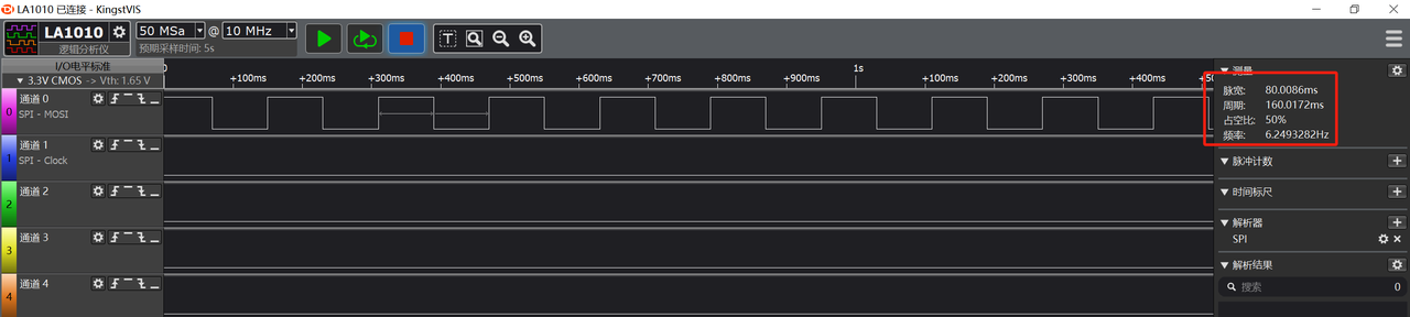
Each complete blinking cycle consists of 320 clock cycles (160 clock cycles for high level and 160 for low level respectively), and the frequency of the finite-state machine is 2000 Hz, so each cycle takes 0.16 seconds, corresponding to an LED blinking frequency of 6.25 Hz:
set (pins, 1)/ set (pins, 0) Instruction: The instruction itself consumes 1 clock cycle, with a latency of 31 clock cycles, totaling 32 clock cycles consumed.
nop () Instruction: Each nop () consumes 1 clock cycle, plus an additional latency of 31 clock cycles, so each nop () consumes a total of 32 clock cycles, and 4 nop () s consume a total of 128 clock cycles.
High level part: set (pins, 1) 4 instances of nop ()= 32 + 128 = 160 clock cycles.
Low level part: set (pins, 0) 4 instances of nop ()= 32 + 128 = 160 clock cycles.
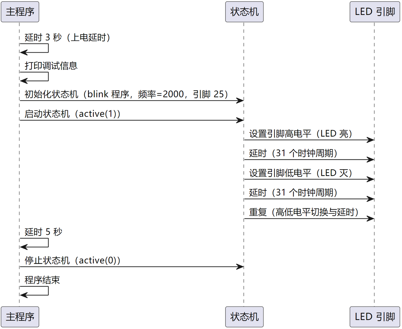
The overall flow of the program is shown in the following figure:
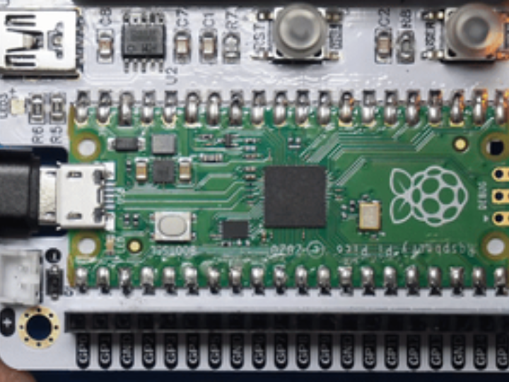
Burn the program into the Pico, and you will see the onboard LED on the Pico blink for 5 seconds and then stop blinking:
We modify the output pin to GP28, and the input command is as follows:
sm = rp2.StateMachine(0, blink, freq=2000, set_base=Pin(28))
sm.active(1)
Here, we use a logic analyzer to observe the output waveform, and it can be seen that the waveform frequency is indeed around the calculated 6.25 Hz: