Pico Potentiometer ADC Practice: LED Control & SerialPlot Waveform Capture
Pico potentiometer ADC hands‑on practice
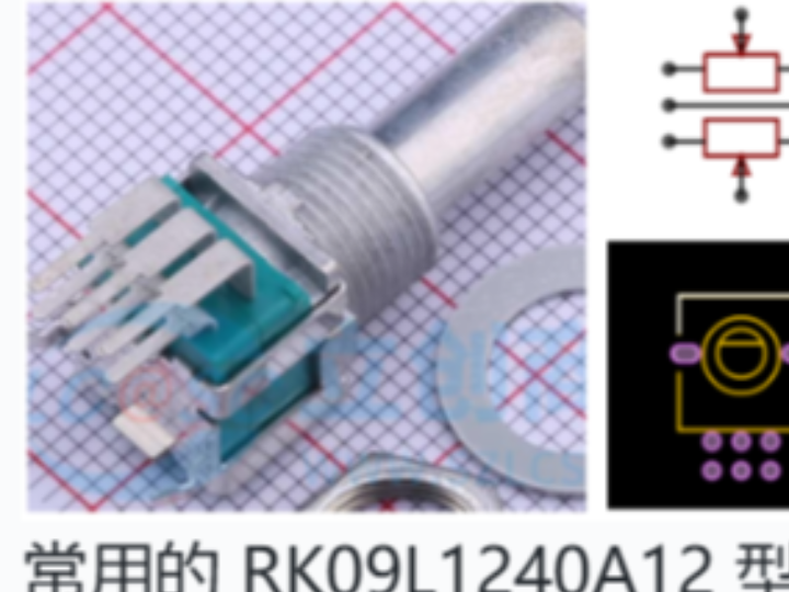
Analog potentiometers are common components in electronic equipment used to adjust voltage or current. They change resistance value by physical rotation, thus altering output‑signal strength. Simply put, a potentiometer is an adjustable resistor with three pins. The two outer pins connect to the two ends of the resistive element. The middle pin (wiper contact) can move to change its contact position along the resistor. When you rotate the potentiometer, resistance between the middle pin and each outer pin changes. This adjusts voltage division and gives control over output signals.
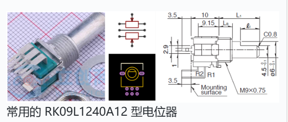
Common RK09L1240A12‑type potentiometer
In this experiment we periodically sample the voltage from an analog potentiometer, adjust onboard LED brightness according to the measured voltage value, and transmit voltage readings over serial port for waveform visualisation using the SerialPlot serial‑plotting tool.
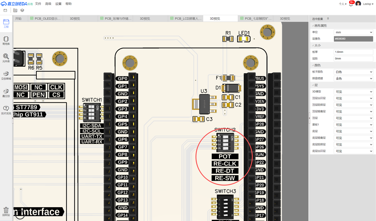
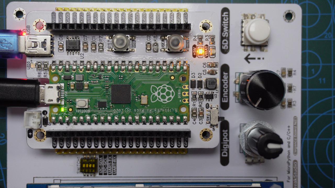
Insert the Elegance‑One Universal Compatible Expansion Board onto the Elegance‑One LCD Human‑Machine‑Interface Board. Toggle the POT option of the SWITCH2 DIP switch on the LCD‑HMI board. Physical connection photos:
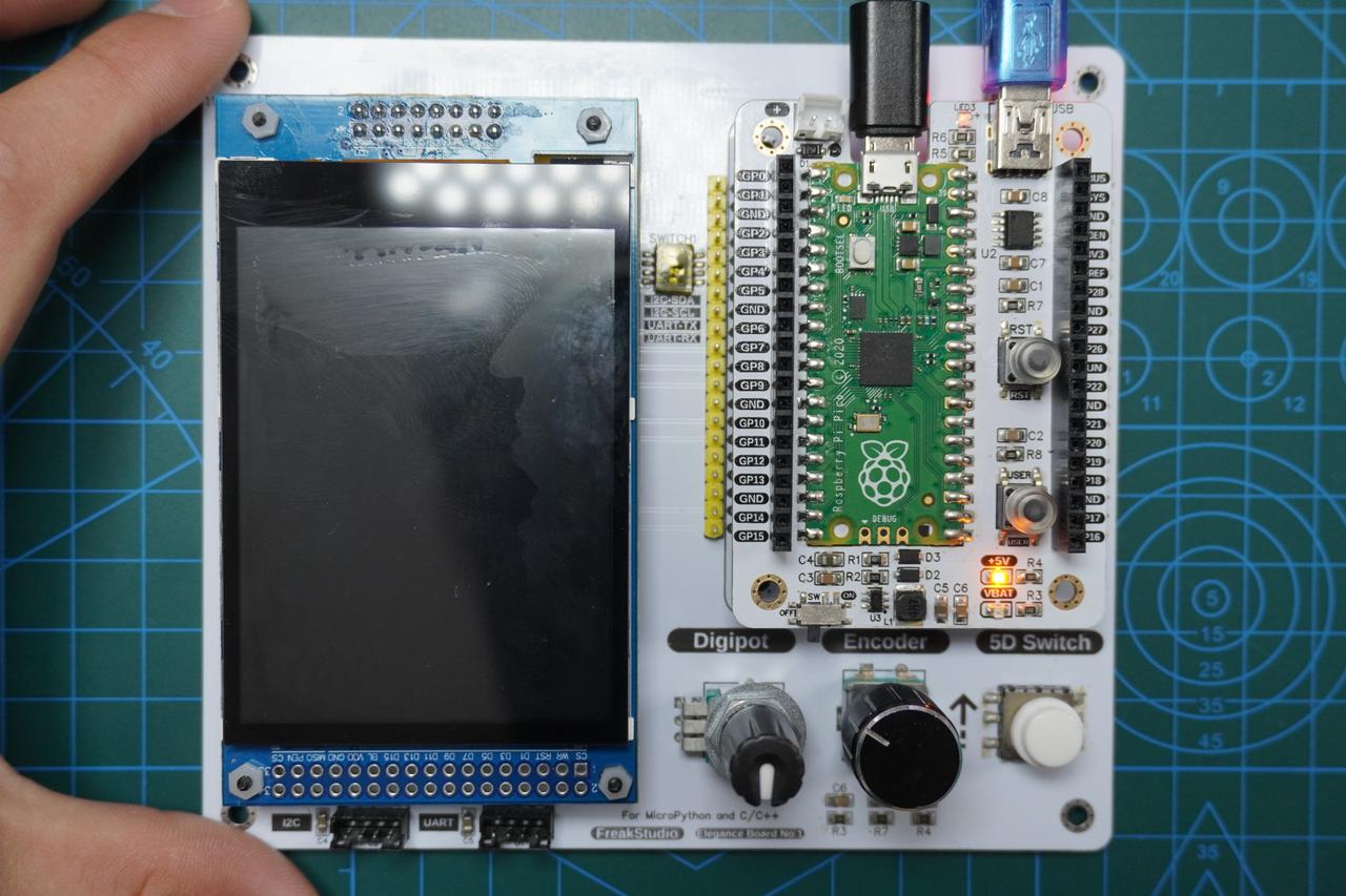
Connect a MiniUSB cable to the serial port on the Elegance‑One Universal Compatible Expansion Board. GP0 and GP1 are the default hardware UART0 pins of Raspberry Pi Pico.
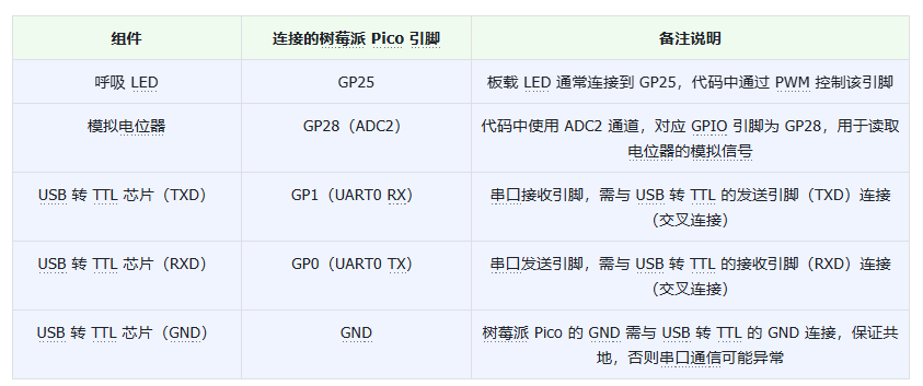
Device wiring table:
Source code is located in the resource package under elegance‑devkit v1\Demo\58 ADC_Potentiometer.
Sample code:
# Python env   : MicroPython v1.23.0
# -*- coding: utf-8 -*-
# @Time    : 2024/8/27 11:33 AM
# @Author  : Li Qingshui
# @File    : main.py
# @Description : ADC experiment, read potentiometer voltage
# ======================================== Import related modules ========================================
# Import hardware‑related modules
from machine import ADC, Timer, Pin, PWM, UART
# Import time‑related modules
import time
# Import module for accessing MicroPython internal structures
import micropython
# ======================================== Global variables ============================================
# ======================================== Function definitions ============================================
# User‑defined callback function
def user_callback(value: float) -> None:
    """
    User‑defined callback function for printing sampled analog potentiometer voltage.
    Args:
        value (float): Sampled voltage value from analog potentiometer.
    Returns:
        None
    """
    global LED, uart
    # Print sampled potentiometer voltage
    print("Analog potentiometer value is %f" % value)
    # Adjust LED duty cycle
    LED.duty_u16(int(value/SimulatedPotentiometer.conversion_factor))
    # Format float value to two decimal places and send over UART
    formatted_value = "{:.2f}".format(value)
    uart.write(str(formatted_value)+'\r\n')
# ======================================== Custom classes ============================================
# Custom potentiometer class
class SimulatedPotentiometer:
    """
    Potentiometer class for reading analog‑potentiometer voltage via ADC pin and updating data periodically with timer.
    This class encapsulates ADC and timer initialization. It provides methods to start / stop sampling and read current voltage.
    User‑defined callback function can be supplied to process sampled voltage values.
    Attributes:
        conversion_factor (float): Voltage conversion factor to convert raw ADC reading to real voltage.
        adc (ADC): ADC instance for reading raw potentiometer data.
        timer (Timer): Timer instance for periodic sampling.
        freq (int): Timer frequency in Hz.
        value (float): Currently sampled voltage value.
        callback (Optional[Callable[[float], None]]): User‑supplied callback for processing voltage readings.
    Methods:
        __init__(self, adc_id: int, freq: int = 100, callback=None):
            Initialize potentiometer instance.
        start(self):
            Start potentiometer sampling.
        _timer_callback(self, timer: Timer):
            Timer callback for reading and converting potentiometer voltage.
        stop(self):
            Stop potentiometer sampling.
        get_value(self) -> float:
            Return current potentiometer voltage value.
    """
    # Voltage conversion factor
    conversion_factor = 3.3 / (65535)
    def __init__(self, adc_id: int, freq: int = 100, callback=None) -> None:
        """
        Initialize potentiometer class instance.
        Args:
            adc_id (int): ADC pin index, must be between 0‑2.
            freq (int): Timer frequency, default 100Hz.
            callback (Optional[Callable[[float], None]]): User callback invoked after sampling completes.
        Raises:
            ValueError: Raised if adc_id is out of 0‑2 range.
        """
        # Input argument validation
        if adc_id > 2 or adc_id < 0:
            raise ValueError("adc_id must be 0~2")
        # Initialize ADC pin and timer
        self.adc = ADC(adc_id)
        self.timer = Timer(-1)
        self.freq = freq
        # Sampled voltage value
        self.value = 0
        # Reference to user‑defined callback
        self.callback = callback
    def start(self) -> None:
        """
        Start potentiometer sampling.
        Args:
            None
        Returns:
            None
        """
        # Start periodic timer and attach callback
        self.timer.init(period=int(1000/self.freq), mode=Timer.PERIODIC, callback=self._timer_callback)
    def _timer_callback(self, timer: Timer) -> None:
        """
        Timer callback: read and convert potentiometer voltage.
        Args:
            timer (Timer): Timer object instance.
        Returns:
            None
        """
        # Read ADC raw value and convert to voltage
        self.value = self.adc.read_u16() * SimulatedPotentiometer.conversion_factor
        # Invoke user‑supplied callback with sampled voltage
        micropython.schedule(self.callback, self.value)
    def stop(self) -> None:
        """
        Stop potentiometer sampling.
        Args:
            None
        Returns:
            None
        """
        # De‑initialize timer
        self.timer.deinit()
    def get_value(self) -> float:
        """
        Return current potentiometer voltage reading.
        Args:
            None
        Returns:
            float: Current potentiometer voltage value.
        """
        return self.value
# ======================================== Initialization ==========================================
# Power‑on stabilization delay
time.sleep(3)
# Print debug message
print("FreakStudio : Analog potentiometer experiment")
# Configure breathing‑LED PWM pin
LED = PWM(Pin(25), freq=100, duty_u16=0)
# Create potentiometer instance, use ADC2‑GP28, 100Hz timer frequency, attach user_callback
potentiometer = SimulatedPotentiometer(2, 100, user_callback)
# Create UART object with baudrate 115200
uart = UART(0, 115200)
# Configure UART parameters: 115200 baud, 8 data bits, no parity, 1 stop bit, tx=GP0, rx=GP1, timeout 100ms
uart.init(baudrate  = 115200,
          bits      = 8,
          parity    = None,
          stop      = 1,
          tx        = 0,
          rx        = 1,
          timeout   = 100)
# ======================================== Main program ===========================================
# Start potentiometer sampling
potentiometer.start()
# Run sampling for 20 seconds
time.sleep(20)
# Stop potentiometer sampling
potentiometer.stop()
# Fetch and print final potentiometer reading
print("Final Potentiometer value:", potentiometer.get_value())
We define class SimulatedPotentiometer to encapsulate potentiometer‑sampling logic. The class reads potentiometer voltage from the designated ADC pin and performs periodic sampling driven by hardware timer.
In main program, potentiometer.start() launches sampling. The timer triggers callbacks at 100 Hz.
On each timer event, _timer_callback executes: it reads current ADC voltage and stores result into self.value, then invokes user‑provided user_callback and passes the voltage value. user_callback does the following work: ‑ Adjust LED brightness proportionally to potentiometer voltage ‑ Format voltage value to two‑decimal‑place string and send it over serial port
After running for 20 seconds, timer is stopped, final potentiometer reading is fetched and printed.
Before flashing firmware, configure SerialPlot serial‑plotting software:

- Configure serial‑port parameters In
Porttab, select correct COM port (exampleCOM4), set baud rate 115200, data bits 8, stop bits 1, no parity. - Click Open button After verifying settings, click
Openbutton at top‑right corner to open serial port.

- Select data format Switch to
Data Formattab, chooseASCIIformat. For single‑channel data stream, keep comma as default data delimiter.
Flash code and open serial terminal. Output:
When rotating potentiometer knob, voltage numbers in terminal update continuously and onboard LED brightness changes accordingly.
SerialPlot displays real‑time waveform. Right‑click and drag box over waveform region of interest:
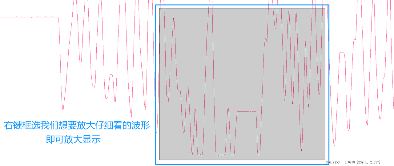
Selected area will be zoomed‑in for detailed inspection:
You can save received data into CSV file during runtime:
Operation steps:
- Before receiving data, go to
Recordtab and pressRecordbutton. Choose target folder and create new CSV file or directly input filename with.csvextension. - Keep
Write header linechecked, so CSV first line contains column headers for later data analysis. Other optional settings:Auto increment file name: Append number suffix automatically to avoid overwriting existing files.Record while paused: Keep logging data even when plot is paused.Stop recording when port closed: Automatically terminate recording upon serial‑port closure.
- Press
Recordbutton again to finish recording.
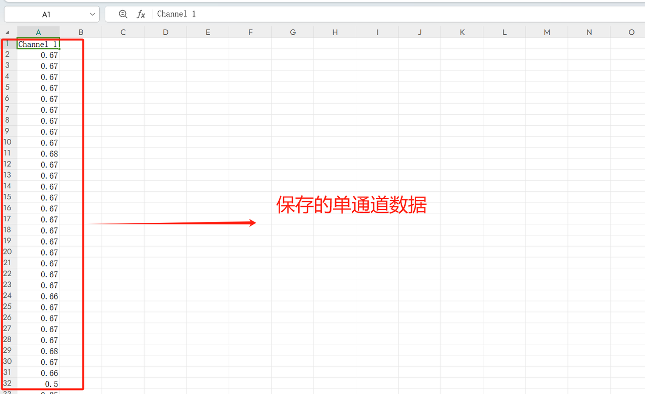
Saved potentiometer voltage CSV data preview: