Pico PIO Assembly Syntax Deep‑Dive: Identifiers, Instructions & Pseudo‑Instructions
pioasm syntax covers identifiers, data types, expressions, labels, instructions with side‑set/delay, and the nop pseudo‑instruction for RP2040 PIO assembly.
COMPONENTS
PROJECT DESCRIPTION
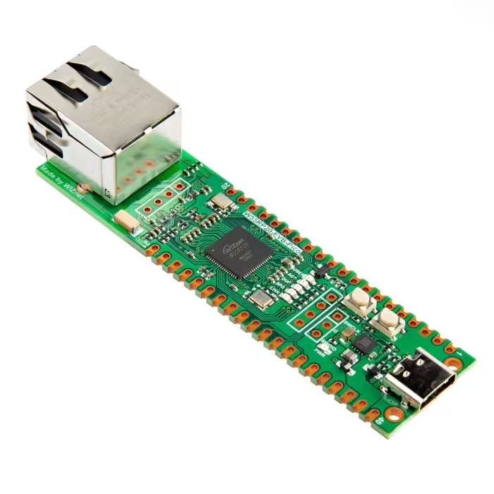
【Preliminary Note】The original hardware example in this article was written based on the RP2040. The actual hardware used in this hands-on demonstration features the W55RP20 as the main controller chip. The circuit logic and UF2 flashing operation principles are universally applicable, with only the main controller model differing. The original chip model mentioned in the circuit descriptions below is provided for reference purposes only.
PIO Assembly Syntax
The PIO assembler (pioasm) is a tool that converts PIO assembly source files into executable machine code, and the assembly code it outputs can be integrated into applications for the RP2040, including C/C++ programs built with the SDK and MicroPython programs; one of the core components of PIO assembly syntax is identifiers, which are used to define program structures, constants, configuration parameters, etc. , and serve as the foundation for writing PIO assembly programs.
1. Identifier
An identifier is a special instruction in PIO assembly used to define constants, program names, memory offsets, and configuration parameters. It is unrelated to register operations and only serves to control the program structure and compile behavior. The following presents the syntax, functions and usage rules of each identifier:
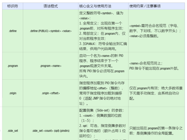
identifier
Syntax Format
Core Meaning and Usage
Usage Restrictions / Notes
.define
.define (PUBLIC) <symbol> <value>
Define the integer symbol <symbol> with the value <value>: 1. Global definition: Appears before the first. program and takes effect for all programs; 2. Local definition: within. program, it only takes effect for the current program; 3. Add PUBLIC: The symbol will be output to the assembly result for calling by user code.
<symbol>Must comply with the naming convention (letters, numbers, underscores, and cannot start with a number); <value> must be an integer.
.program
.program <name>
Start a new PIO program named <name>, which terminates at the next. program directive or the end of the source file. All PIO instructions must be written within the. program block.
<name>The naming convention shall be the same as above; PIO instructions cannot appear outside of .program.
.origin
.origin <offset>
The offset address < offset > (integer) at which the specified program is loaded into the PIO instruction memory is often used to specify that the program is loaded at offset 0 (the absolute address adapted to the JMP instruction).
Only valid within .program; in most scenarios, there is no need to specify manually, and it is automatically assigned by the system.
.side_set
.side_set <count> (opt) (pindirs)
Configure the parameters of the side-set: 1. <count>: Number of bits in the side set data (1~5); 2. opt: Optional, specifies that the side set parameter pair is optional for the instruction (additionally occupies 1 delay bit); 3. pindirs: Optional, specifies that the side set acts on the GPIO direction register (PINDIR) instead of the level register (PIN).
It can only appear before the first instruction of. program; it is the global configuration for side set operations.
.wrap_target
. wrap_target (placed before the instruction)
Marks the starting position for the program's reentry execution: when the program triggers a reentry, execution resumes from the instruction following this identifier.
Only valid within. program; each program can only be used once; If not specified, it will return to the beginning of the program.
.wrap
. wrap (placed after the instruction)
Marks the trigger position for the program's wrap execution: after the instruction preceding this identifier is executed, the program wraps back to the position marked by. wrap_target.
Only valid within. program; Each program can only be used once; If not specified, the return point is located immediately after the last instruction of the program.
.lang_opt
.lang_opt <lang> <name> <option>
Specify options for a specific language generator for the program (such as specifying parameters for the C generator and configuring settings for the MicroPython generator).
Only valid within. program; <lang> refers to the language type (e. g. C, Python).
.word
.word <value>
Stores the 16-bit integer <value> as an instruction into the PIO instruction memory (for manually inserting machine code).
Only valid within. program; <value>is a 16-bit integer (compliant with the machine code format of PIO instructions).
2. Data Types
The data types in PIO assembly are mainly used to define integer constants and specify the target addresses of branch conditions, supporting multiple numerical representation forms and custom symbols. The specific types and their descriptions are as follows:
data type
Description
Example
Typical Applications
integer
Decimal integer value, supporting both positive and negative numbers
3、-7、24
Define the delay period and the initial value of the counter
hex
Hexadecimal value, starting with 0x
0xf (equivalent to decimal 15), 0x10
Indicates hardware register addresses and bitmasks
binary
Binary value, starting with 0b
0b1001 (corresponding to decimal 9)
Indicates GPIO pin combinations and bit operation values
symbol
Symbols (constants) defined by. define
First. define LED_PIN 2, then use LED_PIN
Improve code readability to facilitate unified modification
<label>
The label in the program corresponds to the offset of the instruction in memory
bitloop:(label), jmp bitloop
Branch target address of the JMP instruction
( <expression> )
Evaluable expression with parentheses (parentheses are mandatory)
(5 + 3)、(0x10 - 2)
Complex numerical calculation
3. Expressions
Expressions are used to perform arithmetic and bitwise operations in combination with pioasm values; the operation result is an integer, which can be used as the value of a data type. The specific supported operations and their descriptions are as follows:
Expression Syntax
Description
Example
operation result
<expr> + <expr>
the sum (addition) of two expressions
3 + 5、0x2 + 0x3
8、0x5
<expr> - <expr>
The difference (subtraction) between two expressions
10 - 4、(5 + 2) - 3
6、4
<expr> * <expr>
The product (multiplication) of two expressions
4 * 6、0b10 * 3
24、6
<expr> / <expr>
The quotient of two expressions (integer division, with the fractional part discarded)
7 / 2、10 / 3
3、3
- <expr>
Negative value (negation) of an expression
-5、-(3 + 2)
-5、-5
:: <expr>
Bitwise NOT of an expression (note the use of two colons)
:: 0b1001
0b0110
<value>
Any valid value (as the basis of an expression)
5、LED_PIN
Corresponding value
4. Notes
Comments are used to add descriptive text to code and will not be compiled by the assembler. PIO assembly supports three comment formats to meet different commenting needs:
Annotation Form
Syntax Format
Description
Example
Line Comment (//)
// Comment content
Everything from // to the end of the line is a comment, which is compatible with C/C++ style
set x, 23 // Initialize the loop counter
Line Comment (;)
; Comment content
Everything from ; to the end of the line is treated as a comment, which is compatible with the traditional assembly style
pull; pull data from the TX FIFO
Block comment (/* */)
/* Multi-line comment content */
Multi-line comments start with /* and end with */, compatible with C language style
/* This is a multi-line comment<br>used to illustrate the timing logic of WS2812 */
5. Tags
A label is essentially just an automatic. define, with its value set to the offset of the current program instruction.
The format of the tag is as follows:<symbol>: or PUBLIC <symbol>:.
The tag must start at the beginning of a line.
Labels defined as PUBLIC can be accessed from user code in the same manner as PUBLIC. define directives.
.program example
PUBLIC entry_point: ; 公共标签,供外部代码访问
    set x, 10       ; 指令偏移量0
loop:               ; 普通标签,对应偏移量1
    jmp x-- loop    ; 跳转到loop标签
    jmp entry_point ; 跳转到entry_point标签
In the above example, entry_point has a value of 0 (corresponding to the first instruction), and loop has a value of 1 (corresponding to the second instruction).
6. Instructions
All PIO assembly instructions follow a unified syntax format, support side-set and delay configuration, and serve as the standard specification for PIO instruction programming:
The meanings of the respective parameters are as follows:
parameter
Meaning and Constraint Rules
<instruction>
PIO assembly instructions and their corresponding operands (such as pull, out y, 1, jmp loop) form the core part of the instruction set.
side <side_set_value>
Optional / Mandatory Parameters: 1. Prerequisite: The number of side set bits must be configured via. side_set first, otherwise this parameter will be invalid; 2. Optionality: If. side_set is specified as opt, the field is optional; if not specified, the field is mandatory; 3. Value: The number of bits of side_set_value must be consistent with the number of bits configured by. side_set.
[<delay_value>]
Optional parameters: 1. Value range: The default is 0~31 (5 bits); if the side set is enabled, the number of bits will be reduced (the bits occupied by the side set are deducted from the delay bits); 2. Function: the number of clock cycles for delay after the instruction is executed; if not specified, there will be no delay.
Examples are as follows:
.program example
.side_set 1 ; 配置1位侧集(必选参数)
    pull side 0       ; 侧集值0,无延时
    out y, 1 side 1 [5] ; 侧集值1,延时5个周期
    jmp loop [3]      ; 无侧集(错误,因为.side_set未指定opt,侧集是必选)
    jmp loop side 0 [2] ; 侧集值0,延时2个周期
loop:
    nop side 1 [0]    ; 无操作,侧集值1,无延时
7. Pseudo-instructions
Pseudo-instructions are syntactic sugars provided by pioasm. They are not natively supported by PIO hardware, but are converted by the assembler into equivalent native instructions to simplify programming. Currently, pioasm provides only one pseudo-instruction:
nop Pseudo-instruction: The assembler will convert nop into the native instruction mov y, y (which assigns the value of the Y register to itself without any side effects).
It can be applied in the following scenarios:
Side set coordination operation: when no core instruction needs to be executed, nop is used to trigger the side set control GPIO;
Add delay: executing nop takes up 1 clock cycle, which can be used for fine-tuning the timing;
Placeholder: Fill the instruction memory and adjust the program offset.
.program example
.side_set 1
    nop side 1 [5] ; 无操作,侧集值1,延时5个周期(总耗时6个周期:1个指令周期+5个延时周期)
    nop [3]        ; 无操作,无侧集(若.side_set未指定opt则错误),延时3个周期