This tweet explains RP2040 interrupt architecture, IRQ allocation, NMI mechanism and NVIC priority rules.
COMPONENTS
PROJECT DESCRIPTION
【Preliminary Note】The original hardware example in this article was written based on the RP2040. The actual hardware used in this hands-on demonstration features the W55RP20 as the main controller chip. The circuit logic and UF2 flashing operation principles are universally applicable, with only the main controller model differing. The original chip model mentioned in the circuit descriptions below is provided for reference purposes only.
1. Interrupt
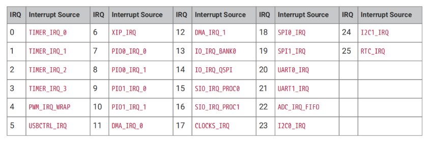
Each core (Core0 and Core1) has an independent NVIC, which acts as a dedicated "interrupt dispatcher" and can receive 32 interrupt signals. However, the RP2040 only uses the first 26 of these (IRQ0 to IRQ25), while the remaining IRQ26 to IRQ31 are reserved (though they can also be forcibly triggered). When a peripheral (such as a timer or UART) triggers an urgent task, it sends a signal to the corresponding IRQ, and the NVIC then schedules the core to process it.
On the RP2040, only the lower 26 IRQ signals are connected to the NVIC, while IRQs 26 to 31 are not tied to any peripheral. By writing to bits 26 to 31 in the NVIC ISPR register, the core can still be forced to enter the corresponding interrupt handler.
The interrupt vector table of the RP2040 is shown below. This table acts as a "task list for IRQs", where each IRQ number corresponds to a specific "source of urgent tasks":
For example, IRQ0 corresponds to "IRQ of Timer 0"(meaning Timer 0 has timed out), and IRQ20 corresponds to "IRQ of UART0"(meaning UART0 has received data). Once the core sees the IRQ number, it can immediately identify which peripheral has sent an "urgent call" and then invoke the corresponding handler.
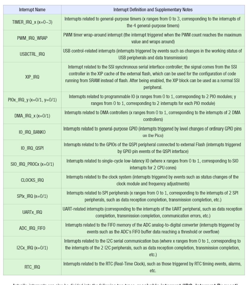
The meanings of the respective interrupts are as follows:
Interrupt Name
Interrupt Definition and Supplementary Notes
TIMER_IRQ_x (x=0~3)
Interrupts related to general-purpose timers (x ranges from 0 to 3, corresponding to the interrupts of the 4 general-purpose timers)
PWM_IRQ_WRAP
PWM timer wrap-around interrupt (the interrupt triggered when the PWM count reaches the maximum value and wraps around)
USBCTRL_IRQ
USB control-related interrupts (interrupts triggered by events such as changes in the working status of USB peripherals and data transmission)
XIP_IRQ
Interrupt related to the SSI synchronous serial interface controller; the signal comes from the SSI controller in the XIP cache of the external flash, which can be used for the configuration of code running from SRAM instead of flash. After being enabled, the XIP block can be used as a normal SSI peripheral.
PIOx_IRQ_y (x=0/1, y=0/1)
Interrupts related to programmable IO (x ranges from 0 to 1, corresponding to 2 PIO modules; y ranges from 0 to 1, corresponding to 2 interrupts for each PIO module)
DMA_IRQ_x (x=0/1)
Interrupts related to DMA controllers (x ranges from 0 to 1, corresponding to the interrupts of 2 DMA controllers)
IO_IRQ_BANK0
Interrupts related to general-purpose GPIO (interrupts triggered by level changes of ordinary GPIO pins on the Pico)
IO_IRQ_QSPI
Interrupts related to the GPIOs of the QSPI peripheral connected to external Flash (interrupts triggered by GPIO pin events of the QSPI interface)
SIO_IRQ_PROCx (x=0/1)
Interrupts related to single-cycle low-latency IO (where x ranges from 0 to 1, corresponding to SIO interrupts for 2 CPU cores)
CLOCKS_IRQ
Interrupts related to the clock system (interrupts triggered by events such as status changes of the clock module and frequency adjustments)
SPIx_IRQ (x=0/1)
Interrupts related to SPI peripherals (x ranges from 0 to 1, corresponding to the interrupts of 2 SPI peripherals, such as data reception completion, transmission completion, etc.)
UARTx_IRQ
UART-related interrupts (corresponding to the interrupts of the UART peripheral, such as data reception completion, transmission completion, communication errors, etc.)
ADC_IRQ_FIFO
Interrupts related to the FIFO memory of the ADC analog-to-digital converter (interrupts triggered by events such as the ADC's FIFO buffer data reaching a threshold or overflow)
I2Cx_IRQ (x=0/1)
Interrupts related to the I2C serial communication bus (where x ranges from 0 to 1, corresponding to the interrupts of the 2 I2C peripherals, such as data reception completion, transmission completion, etc.)
RTC_IRQ
Interrupts related to the RTC (Real-Time Clock), such as those triggered by RTC timing events, alarms, etc.
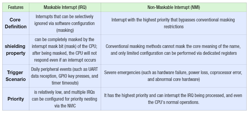
Actually, interrupts can also be divided into the following two types: maskable interrupt (IRQ, Interrupt Request) and non-maskable interrupt (NMI, Non Maskable Interrupt), the core difference between the two lies in "whether they can be selectively ignored by the CPU", which is summarized in the table below:
特性
可屏蔽中断(IRQ)
不可屏蔽中断(NMI)
核心定义
可以通过软件配置(掩码)选择性忽略的中断
优先级最高、突破常规屏蔽限制的中断
屏蔽性
能被 CPU 的中断屏蔽位(掩码)完全屏蔽,屏蔽后即使中断发生,CPU 也不会响应
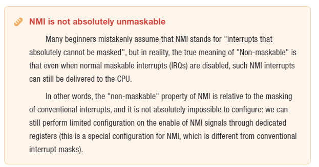
常规屏蔽手段无法屏蔽(名称的核心含义),仅能通过专门的寄存器进行有限配置
触发场景
日常的外设事件(如 UART 收数据、GPIO 按键、定时器超时)
严重的紧急事件(如硬件故障、掉电、协处理器出错、核心硬件异常)
优先级
较低,多个 IRQ 可通过 NVIC 设置优先级嵌套
最高,可打断正在处理的 IRQ,甚至 CPU 的常规操作
Simply put:
Maskable interrupt (IRQ) is a "routine-level" interrupt, for example, the notification alert when a WeChat message arrives on your phone (you can enable Do Not Disturb to block it);
A non-maskable interrupt (NMI) is an "urgent-level" interrupt, such as the alert triggered when a mobile phone detects that its battery is about to run out — this alert will pop up forcibly even if Do Not Disturb mode is enabled.
The 26 system interrupts of the Raspberry Pi Pico (such as TIMER_IRQ, UART_IRQ, GPIO_IRQ, etc.) will undergo two-step processing before being merged with kernel interrupts into a single NMI signal that is fed into the corresponding CPU core. The entire process can be understood as "interrupt filtering and merging":
Step 1: Masking (selectively ignoring some system interrupts): First, 26 system interrupts go through masking processing — which is equivalent to setting a "do not disturb switch" for these interrupts. You can configure the mask register to select "which system interrupts to temporarily ignore even if they occur". For example, you can set to "mask UART_IRQ", then even if the UART receives data, this interrupt will not enter the subsequent processing flow.
Step 2: Perform an OR operation with the kernel interrupt to merge them into an NMI: After being masked, the remaining "non-ignored system interrupts" will undergo an OR operation with the CPU's internal kernel interrupts (such as more severe internal exceptions like power loss, coprocessor operation errors, and hardware faults) — if any one of these interrupts occurs, the result will be "interrupt present". Eventually, these scattered interrupt signals are merged into a unified NMI signal and fed into the CPU core.
The core objective of this process is to: uniformly encapsulate all urgent events requiring top-priority processing into NMI signals, so as to ensure that the CPU can prioritize responding to these critical events.
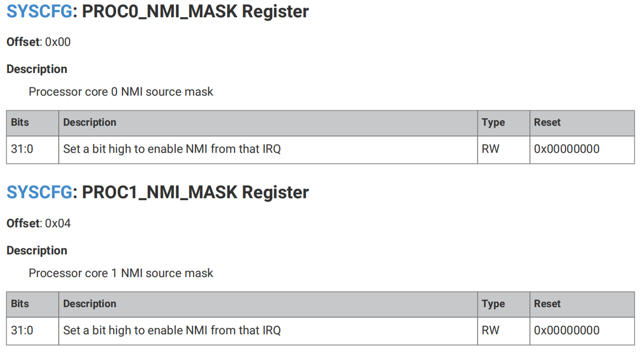
The Raspberry Pi Pico provides dedicated configuration registers for each of the two CPU cores (Core0, Core1). These registers belong to the Syscfg register block (with a base address of 0x40000000) and are used to control the enabling of NMI signals:
PROC0_NMI_MASK Register: Corresponds to Core0 core and is used to configure the NMI signal enable of Core0;
PROC1_NMI_MASK Register: Corresponds to Core1 core and is used to configure the NMI signal enable of Core1.
The core function of these two registers is to precisely control which merged NMI signals can actually be delivered to the corresponding core. For example, you can use the PROC0_NMI_MASK register to set the rule that "only NMI signals related to hardware faults are delivered to Core0, while other NMI signals are temporarily masked". This is a special configuration for NMI, and it is also the only way to "filter" NMI signals.
The bits of the two registers[31:0](32 bits in total) correspond one-to-one to the 32 system IRQs (interrupts) of the Raspberry Pi Pico:
The n -th bit (e. g. bit0, bit5) corresponds to "IRQ n "(e. g. bit0 corresponds to IRQ0, bit5 corresponds to IRQ5).
Function of each bit: Setting a certain bit to 1 (high level) means "enabling the IRQ corresponding to this bit as the NMI interrupt source of the current kernel"; setting it to 0 means "disabling this IRQ as an NMI source".
Its operating characteristics include:
Read/Write Permission (Type: RW): The current value of the register can be read via code, and its bit values can also be modified.
Reset Value (Reset: 0x00000000): After the chip is powered on, all bits default to 0, which means no IRQ is configured as an NMI source by default and manual configuration is required to take effect.
2. NVIC Controller
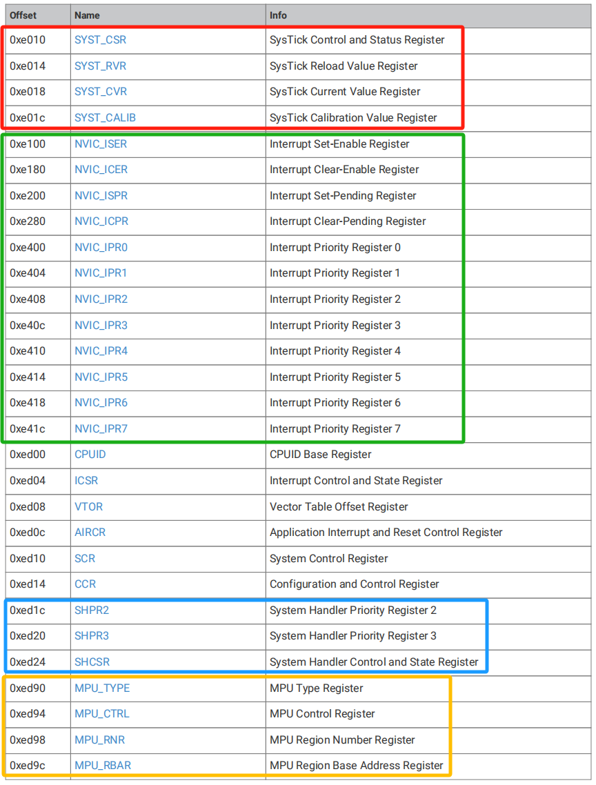
The base address of the registers related to the NVIC interrupt vector controller is PPB_BASE= 0xe0000000, which is a register set in the Raspberry Pi Pico that controls "internal peripherals directly interacting with the core"; these internal peripherals (such as the SysTick timer and NVIC interrupt controller) are core components tightly coupled with the CPU core, responsible for basic functions including core timing, interrupt scheduling, and memory protection.
Special attention: All registers under PPB_BASE can only be read and written in "word (32-bit)" mode (byte/half-word operations are not allowed), and are stored in "little-endian" order (i. e., the lower byte of data is stored at the lower memory address).
Wherein:
The area within the red box contains dedicated registers for SysTick (System Tick Timer);SysTick is a basic timer built into the CPU core, which is commonly used to generate timer interrupts, implement delay functions and other similar features.
The area within the green box contains NVIC (Nested Vectored Interrupt Controller) key registers, which correspond to the previously mentioned "interrupt dispatcher" function and are responsible for interrupt enabling, pending, and priority configuration;
The registers of the system handler inside the blue box are responsible for managing the priority and status of "system-level interrupts"(such as NMI, hard faults);
The content inside the yellow box is the registers of MPU (Memory Protection Unit). The MPU is a component designed to "protect memory regions"(for example, preventing programs from illegally accessing a specific memory segment).
The Raspberry Pi Pico interrupt NVIC supports nested interrupts in hardware: a low-priority interrupt can be preempted by a high-priority interrupt (or another exception such as a hard fault), and the low-priority interrupt will resume once the high-priority exception is completed.
When multiple IRQs are triggered simultaneously, the core processes them in order of "urgency". The NVIC priority level of the RP2040 is 2 bits, which corresponds to 4 types of NVIC interrupt configurations, and the priority is judged in two layers:
NVIC dynamic priority: Each IRQ can be assigned 4 priority levels (0 to 3) via registers, where a smaller number indicates a higher urgency level (for example, level 0 is the highest priority and will be processed before level 1);
IRQ Number Priority: If two IRQs have the same NVIC priority, the IRQ number will be the deciding factor — the smaller the number, the higher the urgency (for example, IRQ0 has a higher priority than IRQ1).
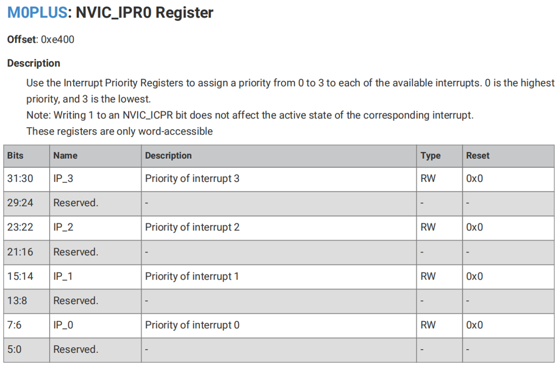
You can use the NVIC_IPRx register (where x ranges from 0 to 7) to set the priority of each interrupt to a value between 0 and 3, with 0 being the highest priority and 3 being the lowest.
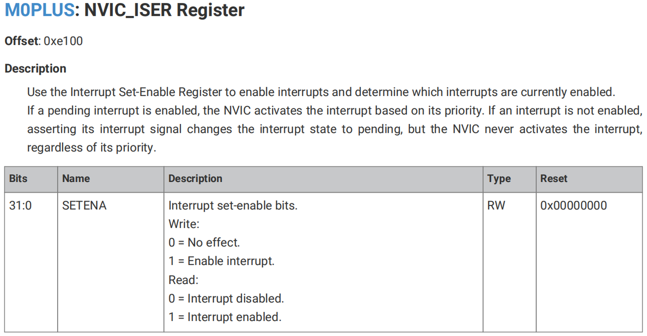
We can use the NVIC_ISER register to enable interrupts or check whether an interrupt is enabled. If an interrupt that is currently pending (meaning a low-priority interrupt has been preempted by a higher-priority interrupt) is enabled, the NVIC controller will activate the interrupt according to its priority. If an interrupt is not enabled, asserting its interrupt signal will set the interrupt to the pending state, but the NVIC will not activate the interrupt regardless of its priority.
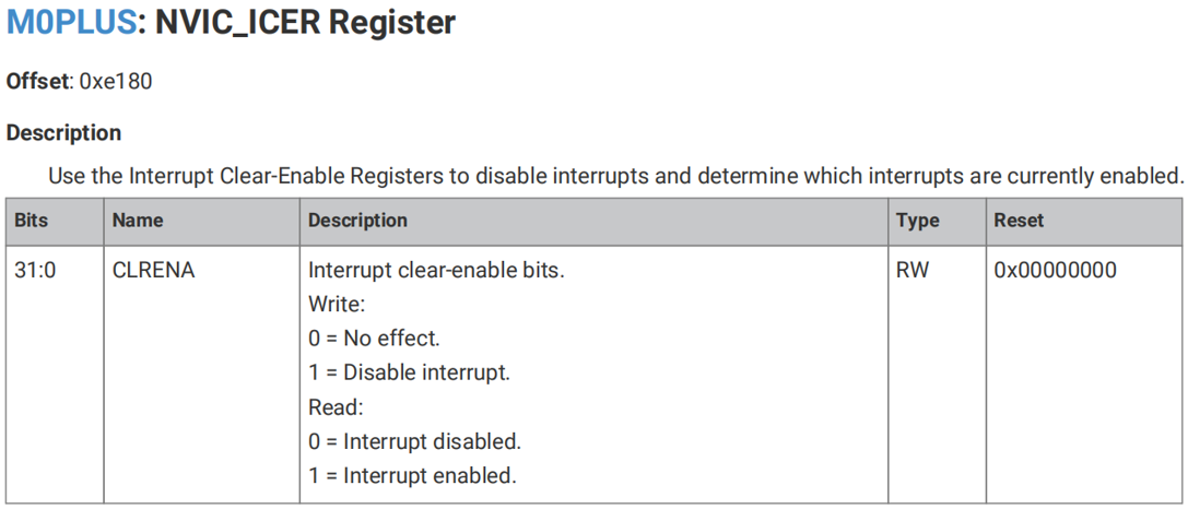
Similarly, we can use the NVIC_ICER register to disable interrupts or check whether an interrupt is disabled.
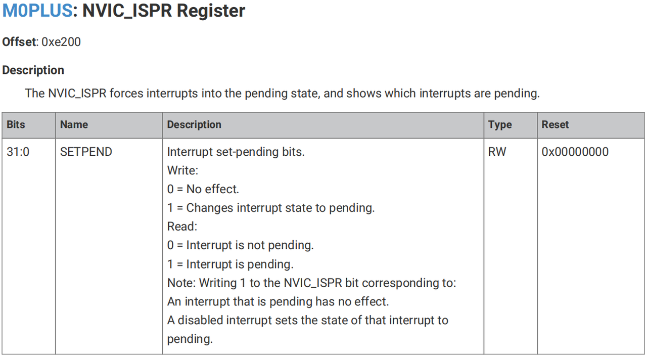
We can use the NVIC_ISPR register to force an interrupt into pending state or check whether an interrupt is pending.
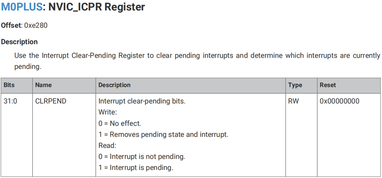
Similarly, we can use the NVIC_ICPR register to clear the pending status of an interrupt or check whether an interrupt is pending.