One‑of‑a‑Kind Guide: MicroPython Storage & File‑System Internals, Beginner‑Friendly Complete Tutoria
Beginner‑friendly complete guide covering MicroPython memory layout, Flash/SRAM partitions, VFS, block‑devices, FAT and LittleFS underlying working principles
- Storage Areas in MicroPython
When learning MicroPython, understanding storage areas is equivalent to knowing where your programs "live" and which "cabinet" holds different pieces of data. Knowing data‑storage rules helps you avoid memory overflow and mysterious data corruption, and also lets you grasp underlying program‑execution logic.
Two essential beginner‑level concepts:
Flash Think of it as a computer hard drive. Data survives power loss, read‑write speed is relatively slow. Used for long‑term persistent content. MicroPython firmware and user program code are stored here.
SRAM (Static Random‑Access Memory) Think of it as computer RAM. All data is lost after power‑off, but read‑write speed is extremely fast. Used for temporary, frequently‑changing runtime data.
MicroPython storage layout resembles memory models seen in traditional languages such as C/C++. It has two major storage groups: Flash and SRAM, each containing functional sub‑sections with dedicated responsibilities.
Content inside Flash is comparable to movies burned onto an optical disc. It normally stays unchanged and persists through power cycles. It holds static content:
Code Section Stores program code including bytecode or compiled machine instructions plus underlying interpreter code. Read‑only and unmodified during runtime.
Read‑Only Data Section Holds constant values such as string literals e.g. "hello MicroPython", module‑level constants e.g. MAX_NUM = 100. Data remains unchanged while the program runs and may be reused throughout execution. For example the string "hello" used multiple times only occupies one copy inside this section to save space.
SRAM behaves like temporary scratch‑paper on a desk. Contents may be modified freely and vanish on power loss. It holds temporary runtime‑changing content:
Data Section Stores global variables of the MicroPython interpreter, accessible across the whole program from startup until power‑down or program termination. For instance total = 0 defined at outermost program scope resides in the data section. Modifications from any function operate on this single copy.
Heap Section The most flexible area within SRAM. Dedicated for MicroPython dynamic objects and dynamically‑allocated data: examples include lists [1,2,3], dictionaries {"name":"XiaoMing"}, instances of custom classes e.g. class Car: ...; my_car = Car(), plus local variables inside functions. The interpreter allocates heap memory on demand via its memory allocator e.g. creating a new list carves out heap space for that list. A built‑in Garbage Collector (GC) automatically reclaims heap memory belonging to unreferenced objects such as unused lists, preventing memory exhaustion.
Stack Section Handles function‑call‑related operations: recursive invocations and local variables inside functions e.g. variable num in def calc(): num=10; print(num). Total stack capacity is limited and varies according to hardware SRAM size. Stack size adjusts dynamically with function calls and returns. Space is allocated for function local variables on function entry and released when the function returns. Risk warning: Excessively deep recursion such as infinite recursion fills stack capacity and triggers stack‑overflow crashes, analogous to writing past the physical edge of scratch‑paper.
- File Systems in MicroPython
2.1 Concept and Composition of File Systems
A file system is the structure and set of methods used by operating systems to manage files on storage media such as hard disks, solid‑state drives and flash memory. It handles file creation, reading, writing, deletion plus directory organisation so users and applications can store and retrieve data in structured fashion.
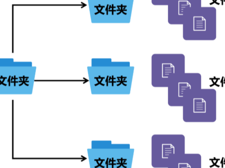
You may visualise a file system as organisational rules for storage devices like USB flash drives or embedded boards: similar to rules for drawer compartments that define which compartment holds documents and which holds photos. The file system governs where files are kept, how to locate them and efficient storage strategies.
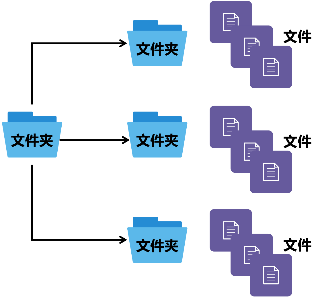
Typical file‑system capabilities:
File management: create, read, write and delete files.
Directory management: create, read and delete directories.
Storage management: allocate storage space for files and track storage usage.
FAT is one straightforward file‑system variant widely deployed on embedded hardware.
Fundamental concept:
Cluster The minimum allocation unit of a file system. Storage media is divided into many equal‑sized compartments called clusters. One file occupies one or more clusters. Even very small files consume at minimum one full cluster.
Taking the FAT file system as example, a complete file system consists of these components:
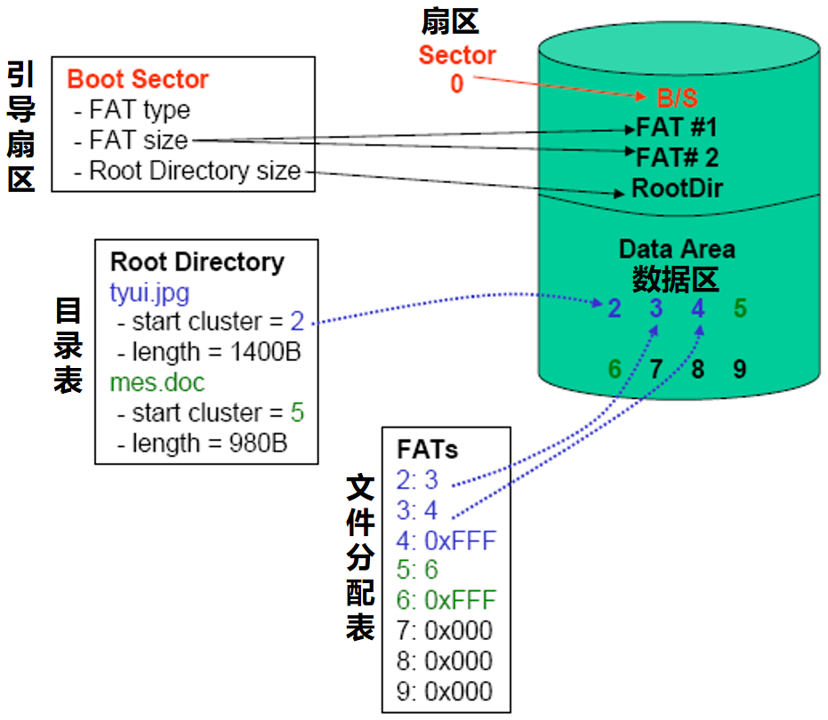
File systems divide storage space into clusters. A cluster contains one or more sectors, where the sector represents the smallest physical storage unit. Cluster sizes differ across file‑system implementations. For FAT12/FAT16 common cluster sizes are 512 Byte, 1 KB, 2 KB or 4 KB.
Boot Sector The instruction manual for the file system, the very first block of storage media. It records: File‑system type (FAT12 / FAT16 / FAT32). Bytes per cluster, location of FAT tables, root‑directory size. Hardware reads this boot‑sector information during power‑on before it can interpret remaining stored files.
Directory Table File inventory list, corresponding to Root Directory. It stores key metadata for each file: Filename e.g. tyui.jpg, mes.doc. File size e.g. tyui.jpg is 1400 B. Starting‑cluster number indicating which cluster holds the beginning of file data. When locating a file you first consult this inventory to retrieve its name, size and starting‑cluster index.
File Allocation Table (FAT) Cluster navigation map represented as an array. Since a single large file may span multiple clusters, FAT records which cluster follows each existing cluster. Table entry meanings: 0x0000: cluster is free / available. 0xFFFF: final cluster belonging to a file (end marker). 0xFF7F: bad cluster which cannot store data.
Example for tyui.jpg starting from cluster 2: FAT entry for cluster 2 points to 3. Cluster 2 is followed by cluster 3. FAT entry for cluster 3 points to 4. Cluster 3 is followed by cluster 4. FAT entry for cluster 4 equals 0xFFFF. Cluster 4 is the final cluster. Therefore tyui.jpg resides inside clusters 2, 3, 4.
For mes.doc starting from cluster 5: FAT entry for cluster 5 points to 6. Cluster 5 is followed by cluster 6. FAT entry for cluster 6 equals 0xFFFF. File terminates. mes.doc occupies clusters 5 and 6.
Data Area Actual payload storage area. Real file contents such as image bytes for tyui.jpg and document content for mes.doc are saved inside clusters belonging to this region. Directory‑table and FAT metadata provide navigation; raw file data lives within these clusters.
Common file‑system types include FAT (FAT12, FAT16, FAT32), NTFS, ext, LittleFS and others. FAT is popular for embedded use cases due to simple design, easy implementation and low overhead. However: Maximum supported individual‑file size is limited; FAT16 for instance caps files at 2 GB. Fragmentation may occur as files are created / erased: file data spreads across disjoint clusters and slows access performance. There exists no native permission or security mechanism; files may be freely modified with limited recovery options after corruption.
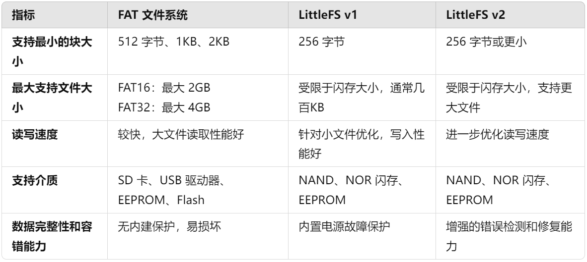
Three file‑system variants are most frequently used within MicroPython: FAT, LittleFS v1 and LittleFS v2.
2.2 VFS Virtual File System
Two foundational beginner‑friendly definitions for understanding VFS:
Abstraction Layer Acts as a universal translator. Regardless of underlying "dialect" i.e. different file‑system implementations, it exposes one consistent set of application‑level APIs.
Block Device Generic term for storage hardware such as SD‑cards or on‑board flash chips. Reads and writes operate in fixed‑size blocks; this hardware forms the carrier underneath any file system.
VFS (Virtual File System) is a MicroPython module delivering file‑system support for embedded targets. It is an abstraction layer providing uniform file‑system APIs: Applications can invoke identical functions to interact with diverse underlying file‑systems (FAT, SPIFFS, LittleFS) without implementation‑specific code changes. In short: whether you target FAT on SD‑card or LittleFS on board flash, VFS supplies identical operation functions for reading / writing files, removing the requirement to learn new commands for each storage medium.
Users may mount different file‑systems onto specific paths and unmount them when needed. Mounting may be visualised as attaching an access‑point: mount SD‑card under /sd path, then all operations targeting /sd interact with the SD‑card. Unmount safely removes this access‑point to prevent data corruption.
Example workflow: mount SD‑card FAT to /sd, mount SPIFFS to /spiffs. Both are managed through identical file‑operation APIs. Using the VFS module you may also create software‑emulated block‑devices e.g. virtual RAM‑disk.
VFS mount and unmount functions:
vfs.mount(fsobj, mount_point, *, readonly): attach storage access‑point
Description: attach a file‑system object (FAT / LittleFS) onto a specific system path e.g. /sd. Subsequent file operations on that path target the storage.
Parameter explanation: fsobj: target file‑system object such as FAT / LittleFS instance or raw block‑device object like SD‑card object. mount_point: access‑point path e.g. '/' for root directory or '/sd' for SD‑card dedicated mount‑point. readonly (optional): True for read‑only access; default False enables read‑write.
Exception note: raises OSError(EPERM) if mount‑point is already occupied by another mounted device.
vfs.umount(mount_point): safely detach access‑point
Description: detach previously‑mounted file‑system. For example unmount SD‑card before physical removal to avoid data loss.
Parameter: supply mount‑point path string e.g. '/sd' or original mounted file‑system object.
Exception note: raises OSError(EINVAL) if the given mount‑point has nothing mounted.
VFS itself is only the manager. You must instantiate concrete file‑system objects (FAT / LittleFS) before calling mount. Below are the available file‑system implementation classes.
File‑system classes for constructing FAT, LittleFS v1, LittleFS v2 etc:
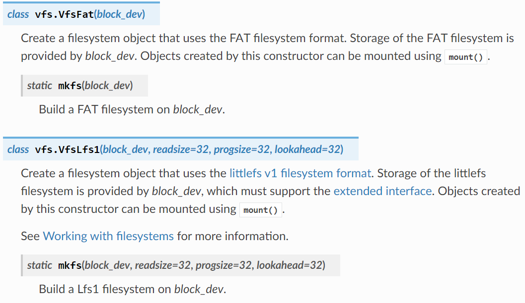
vfs.VfsFat(block_dev): create FAT file‑system object
Purpose: generate FAT‑managed storage object, commonly used for SD‑cards. block_dev represents underlying block‑device such as SD‑card instance.
mkfs method: performs formatting. Example vfs.VfsFat.mkfs(sd_dev) formats SD‑card sd_dev as FAT so files may be stored.
vfs.VfsLfs1(block_dev, ...) / vfs.VfsLfs2(...): create LittleFS file‑system object
LittleFS is a lightweight embedded‑oriented file‑system better suited for small flash chips than FAT; available in v1 and v2 revisions.
Purpose: generate LittleFS‑managed storage object; block_dev is target block‑device such as on‑board flash.
Optional parameters: readsize / progsize configure read / program block‑size; beginners may keep default value 32. The v2‑specific mtime option enables file‑modification timestamp recording.
mkfs method: example vfs.VfsLfs2.mkfs(flash_dev) formats on‑board flash flash_dev into LittleFS v2.
vfs.VfsPosix(root=None): access host‑computer file‑system (debug‑only)
Purpose: when MicroPython runs on PC host, this class accesses the host computer filesystem. root accepts host‑side path e.g. 'C:/test'. Omitted argument uses current working directory.
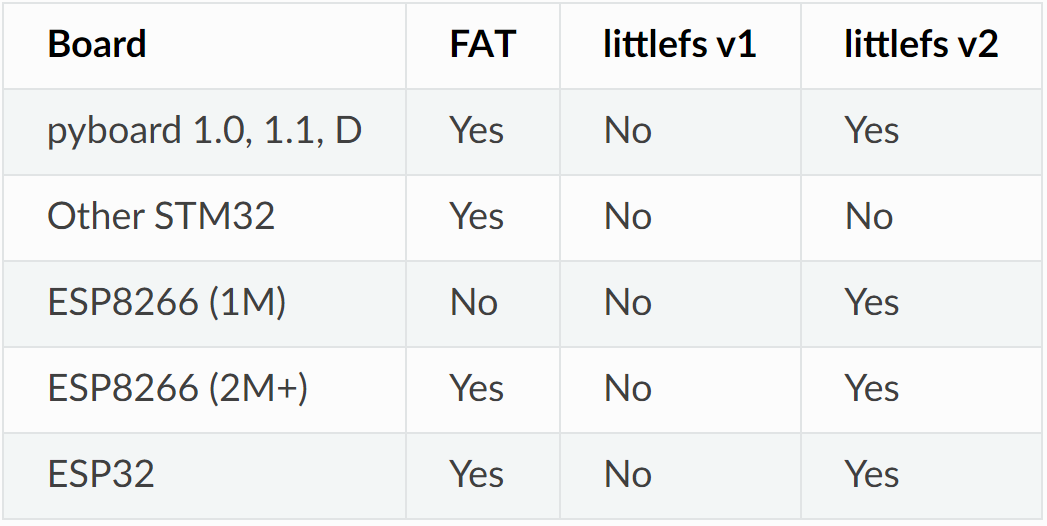
Table showing built‑in file‑systems present inside default MicroPython firmware for different chips:
2.3 Block Devices
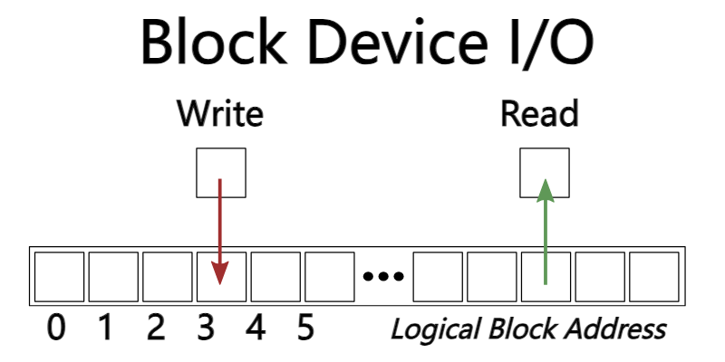
File systems sit on top of block devices. A block‑device divides storage space into fixed‑size blocks supporting random‑access operations: each block possesses unique logical address and may be independently read or written. In brief: block‑devices store data inside blocks. File‑systems organise these blocks into files and directories for convenient end‑user access.
Storage space is split into uniform‑size blocks e.g. 1 KB per block, each assigned unique logical‑block address such as 0, 1, 2, 3…. Read‑write operations specify target block‑address directly e.g. write block 3, read block 8; you are not forced to scan sequentially starting from block 0. File‑systems (FAT, LittleFS etc.) map these raw blocks onto files and directories. One file may occupy blocks 3, 4, 5; the file‑system maintains metadata recording which blocks belong to that file.
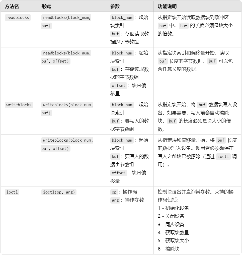
MicroPython does not supply concrete block‑device implementation code, but provides abstract base class vfs.AbstractBlockDev. This abstract template defines mandatory methods such as read‑block and write‑block, comparable to answer‑sheet format specification. Only classes conforming to this interface are recognised as valid block‑devices where you can build file‑systems.
Concrete block‑device classes must implement the methods shown below: