MicroPython RS485: MAX13487 Master-Slave Communication Project
This tutorial covers RS485 fundamentals, MAX13487 chip, and a MicroPython RS485 implementation on Raspberry Pi Pico.
COMPONENTS
PROJECT DESCRIPTION
【Preliminary Note】The original hardware example in this article was written based on the RP2040. The actual hardware used in this hands-on demonstration features the W55RP20 as the main controller chip. The circuit logic and UF2 flashing operation principles are universally applicable, with only the main controller model differing. The original chip model mentioned in the circuit descriptions below is provided for reference purposes only.
Tweet
1. Basic Knowledge of RS485 Communication
The RS-232 Communication Protocol has the following drawbacks, which make it difficult to apply in long-distance and industrial scenarios:
High signal level: The signal level of RS-232 is typically around ±12V, and may even reach ±15V; such a high level can easily damage the chips in the interface circuit. If connection to low-voltage TTL circuits (e. g., 5V or 3.3V) is required, a level conversion circuit must be used to protect the device and achieve signal matching.
Low transmission rate: The baud rate of RS-232 is relatively low. Especially in asynchronous transmission scenarios, its maximum rate is only 20Kbps, which is far from meeting the requirements of modern high-speed communication, particularly in application scenarios that require fast data exchange.
Poor anti-interference performance: RS-232 adopts a single-ended signal transmission mode, where a signal loop is formed by one signal line and one common ground line. This structure is susceptible to common-mode interference, which degrades signal quality and results in weak anti-noise performance, a drawback that becomes particularly pronounced during long-distance transmission.
Limited transmission distance: The standard specifies that the maximum transmission distance of RS-232 is 50 feet (approximately 15 meters). In practice, the transmission distance generally does not exceed 50 meters; beyond this distance, the signal will attenuate significantly, making it impossible to guarantee the reliability of communication.
Therefore, subsequent engineers developed the RS-485 Communication Protocol. Compared with the RS-232-C interface, RS-485 has significant advantages in terms of transmission distance, anti-interference capability, multi-device communication and other aspects:
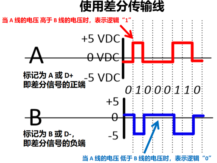
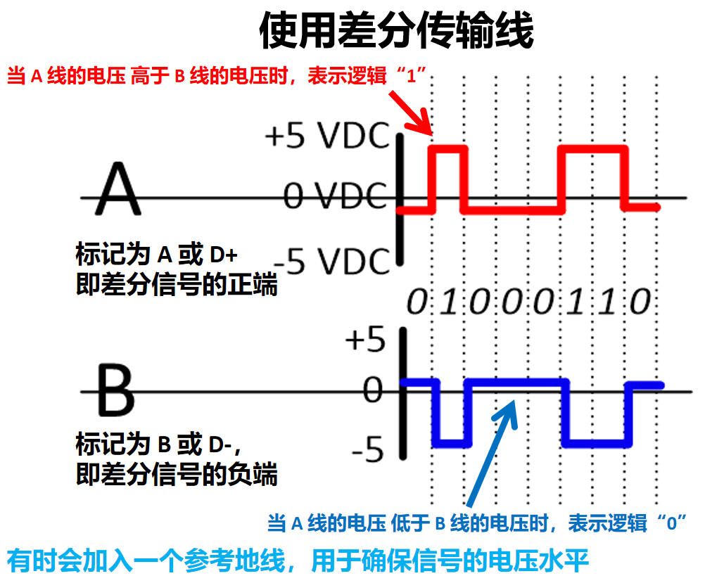
Differential Signal Transmission: RS-485 uses two signal lines (A and B) to represent "0" and "1" through voltage difference; this differential transmission method can effectively resist electromagnetic interference and ensure stable communication in noisy environments.
Multi-point communication: RS-485 allows multiple devices to be connected to the same bus. Typically, it supports 32 transmitters and 32 receivers, and even more devices can be connected via repeaters, which makes RS-485 highly suitable for scenarios requiring interconnection of multiple devices.
Long-distance transmission: The maximum transmission distance of RS-485 can reach 1200 meters (approximately 4000 feet), and the transmission speed is inversely proportional to the distance; as the transmission distance decreases, the data transmission rate can be increased, up to a maximum of 10 Mbps.
Unlike RS-232 or TTL, RS-485 operates in half-duplex mode in most applications, meaning that only one device can transmit data at a time while all other devices remain in the receiving state, thus an additional protocol is required to coordinate communication between devices.
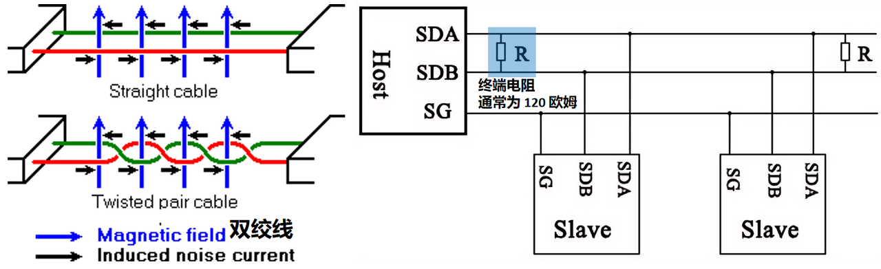
The typical topology of the RS485 bus is that multiple devices are connected in series on a single trunk line; each device is equipped with an independent transmitter and receiver, and shares a pair of communication lines (A and B). We usually use twisted-pair cables to reduce electromagnetic interference and noise. Meanwhile, for long-distance or high-speed transmission, terminal resistors (typically 120 ohms) are usually added at both ends of the bus to avoid signal reflection and interference.
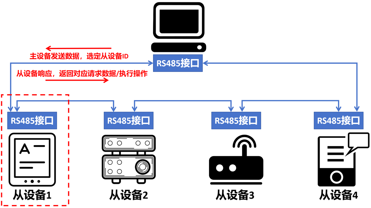
In the master-slave architecture of RS-485 communication, different devices can be divided into two roles:
Master Device (Master): responsible for controlling the entire communication process, initiating data requests, and sending commands and data to slave devices
Slave Devices: Each slave device has a unique device ID (address) and passively responds to the requests from the master device during communication. Only when the master device sends a matching address to it will the slave device process the data and send a response as required.
The communication process can be summarized as follows:
Master device data transmission: The master device transmits data via the RS-485 bus, which contains the address of the target slave device (slave device ID) and specific data; both line A (+ signal) and line B (- signal) are connected to all slave devices simultaneously.
Slave Listening: All slave devices monitor the data streams on lines A and B, and check the address information sent by the master device
Slave device selection: When a slave device detects that the address in the transmitted data packet matches its own slave device ID, it will receive the data packet and perform corresponding processing.
Slave Device Response: If the Communication Protocol requires the slave device to return data (such as status information, sensor data, etc.), the slave device will send response data to the master device; RS-485 is generally half-duplex, which means only one device can transmit data at the same time, so the transmission of response data needs to be carried out according to a predetermined timing sequence
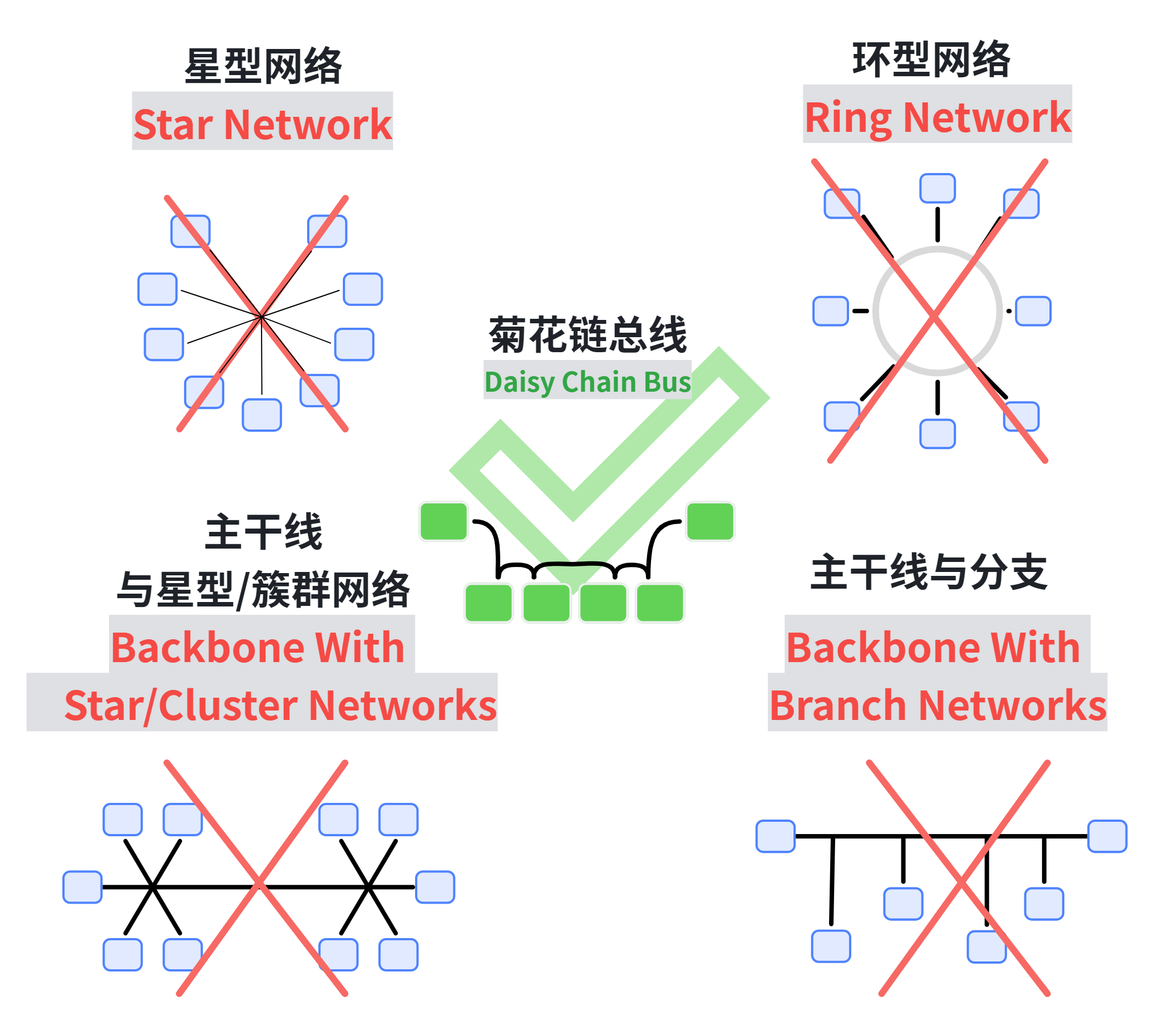
Network topology recommendation and avoidance diagram
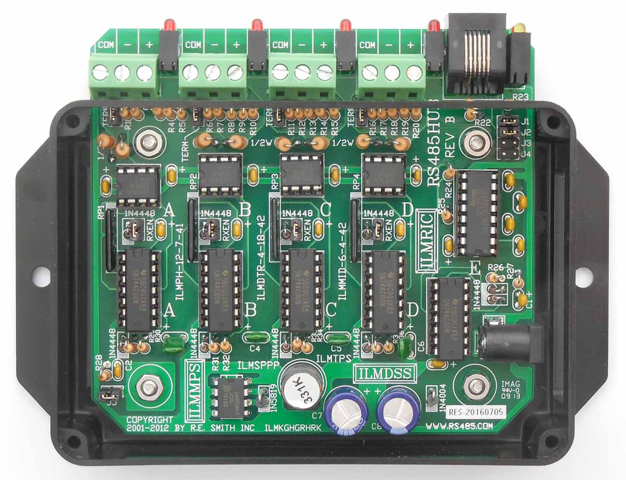
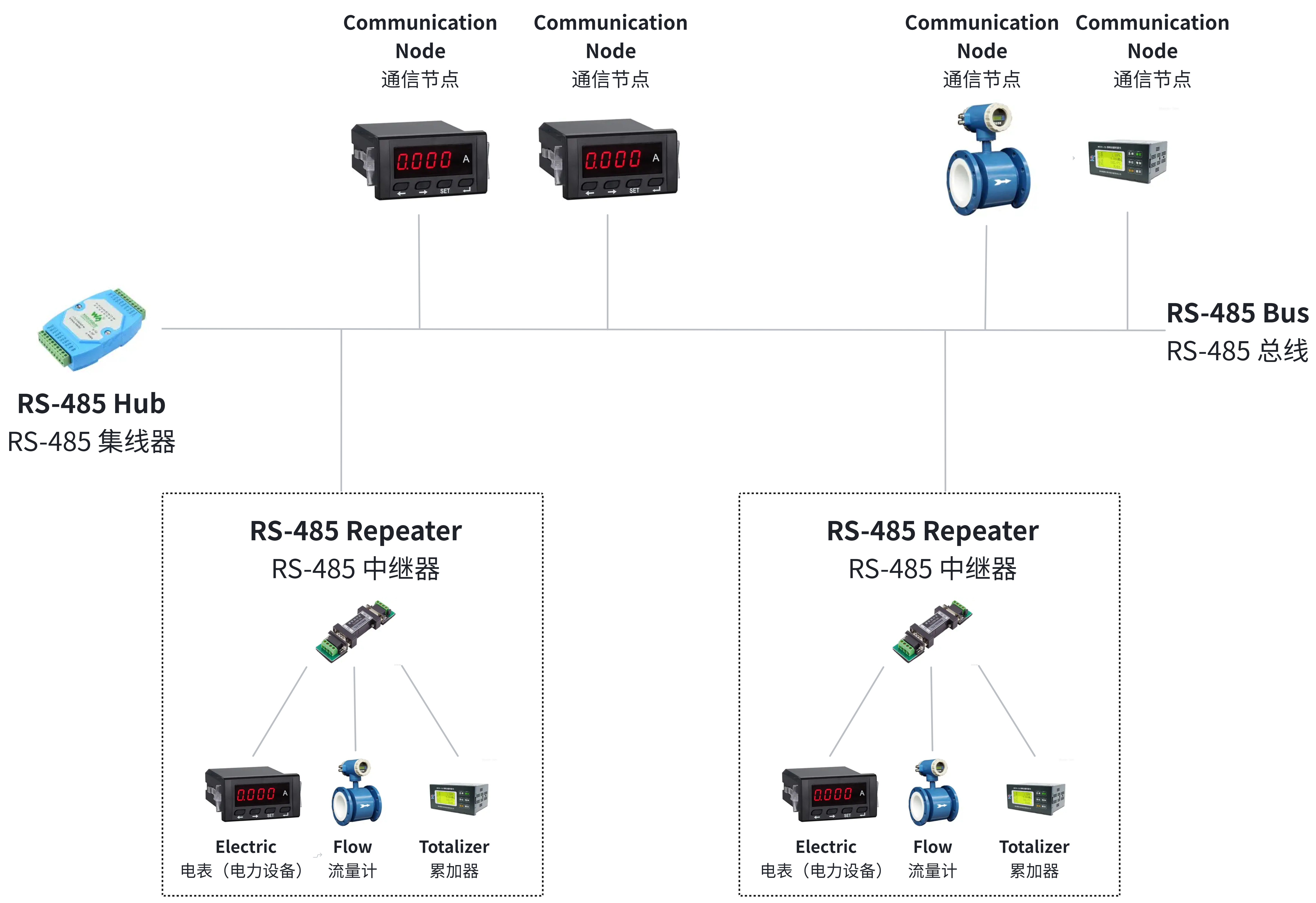
With the exception of the daisy-chain bus (which connects devices in series one after another to form a single-path communication link), other topologies are not recommended for use in RS485 communication, as they will cause severe signal reflection and interference problems. If a topology such as a star topology has to be used, an RS-485 hub or repeater must be used to avoid signal reflection and interference:
RS485 Hub
Schematic Diagram of RS485 Hub Connection
When using RS485 communication, it is imperative to note that RS-485 signal lines and power lines must not be routed together in bundles. This is because power lines generate strong electromagnetic interference, which will interfere with the signal lines transmitting data; meanwhile, the RS-485 bus requires single-point grounding, meaning there can only be one grounding point on the bus. If multiple grounding points occur, potential differences between ground wires will be caused, which will further trigger common-mode interference and affect the stability of communication.
RS485 communication also supports full-duplex data transmission, in which TX and RX have separate lines for communication, but in this case, slave devices cannot communicate directly with each other and must transmit data via the master device.
2. Introduction to the MAX13487 Chip
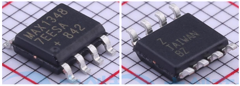
The MAX13487E is a high-performance, half-duplex RS-485/RS-422 compatible transceiver featuring ±15kV electrostatic discharge (ESD) protection, supporting both automatic transmit/receive control function and power-down mode, with a maximum supported communication rate of 500kbps. It also enables hot-swapping under power-on conditions to prevent data errors, and allows up to 128 transceivers to be connected to the same bus.
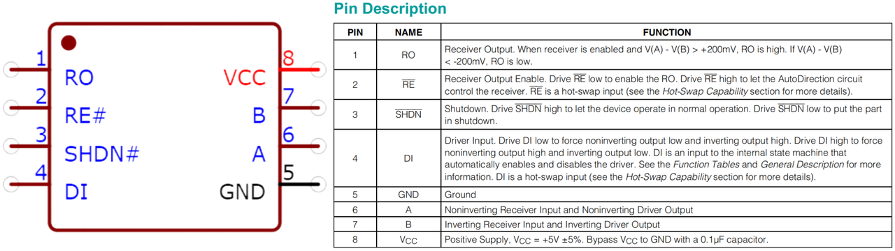
The functions of its pins are shown as follows:
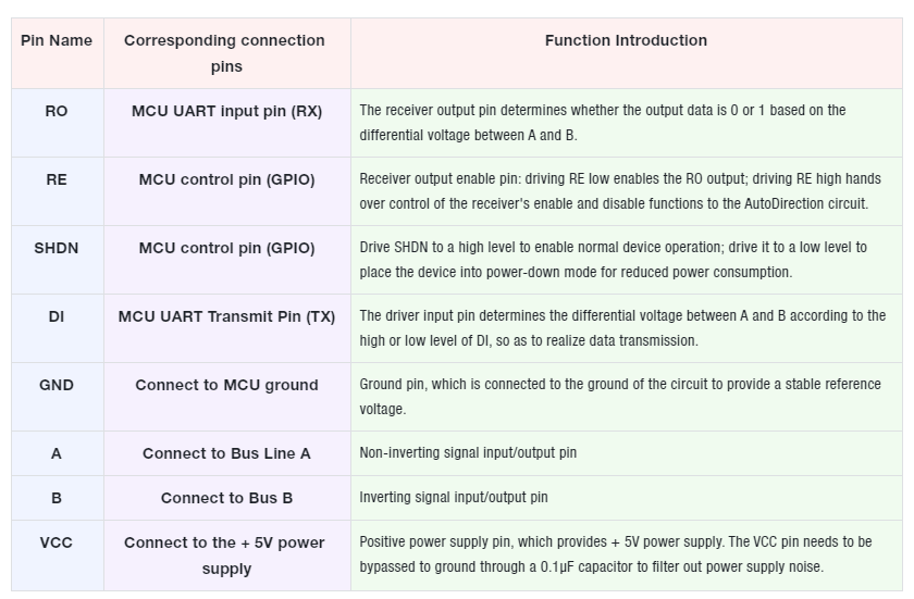
In the table below, we will provide a detailed explanation:
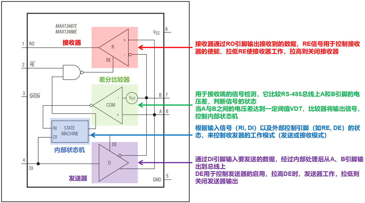
The internal structure of the MAX13487E chip is shown as follows:
The main working units are the internal finite-state machine, transmitter, differential comparator and receiver. Together with the external pull-up and pull-down resistors for the A-phase and B-phase signals, the MAX13487 chip can easily implement the automatic transceiving function by monitoring the voltage difference on the data input (DI pin) and the differential signal lines (pins A and B), without the need for users to use additional GPIO pins to control transceiving.
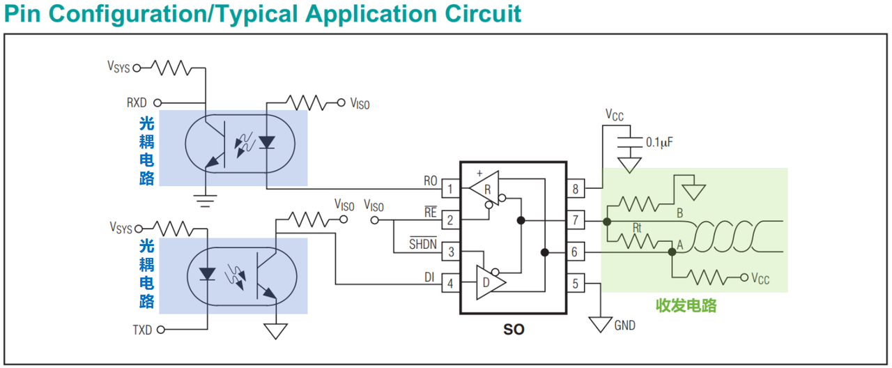
The typical application circuit of the MAX13487E chip is shown in the following figure:
Among them, the TXD pin and RXD pin of the UART corresponding to the MCU are connected to the RO and DI pins of the MAX13487 chip through an optocoupler isolation unit; the RE and SHDN pins of the MAX13487 chip are both connected to a high level, which disables the power-down mode and activates the automatic transceiving function. A termination resistor is connected to the differential signal input/output pins to match the impedance of the communication bus; meanwhile, the A pin is connected to the power supply via a pull-up resistor, and the B pin is connected to ground via a pull-down resistor, thereby generating a small differential voltage to ensure that the voltage of the A pin is higher than that of the B pin, so that the bus can maintain a logic "1"(i. e., A > B) when idle.
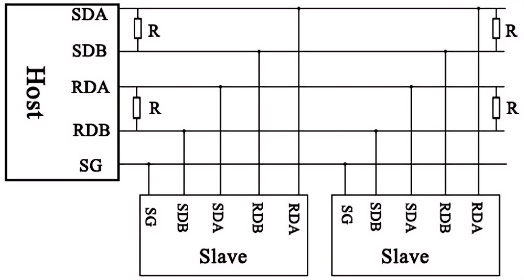
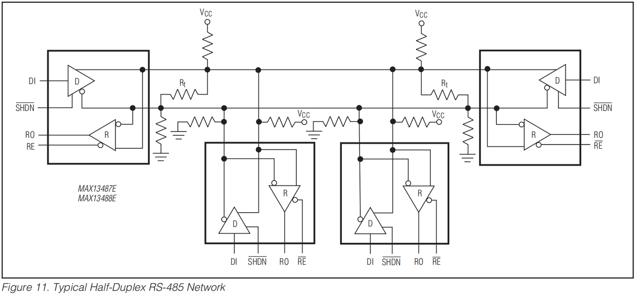
When multiple devices use the MAX13487 chip for RS485 communication, their connection topology is shown as follows:
All devices are connected together via a pair of differential signal lines (A and B), and termination resistors are typically installed at both ends of the bus.
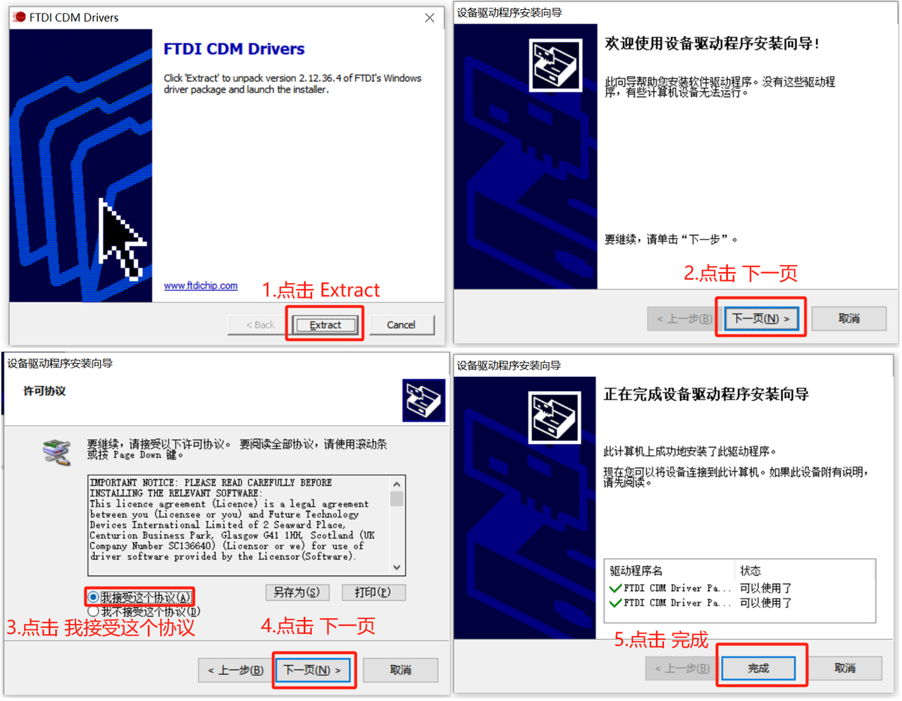
Here, we use a USB-to-485 adapter to enable communication between the Raspberry Pi Pico with an externally connected MAX13487 chip and the host computer. This USB-to-485 adapter adopts the FT232 chip, for which we need to install the corresponding driver. In addition to downloading the corresponding driver from FTDI's official website:
https://ftdichip.com/drivers/vcp-drivers/
can also be found in the resource package we provide:
Double-click with the left mouse button and follow the steps below to install:
3. Application Experiment
Here, in the following code, we implement the communication between the Raspberry Pi Pico's externally connected MAX13487 chip and the host computer.
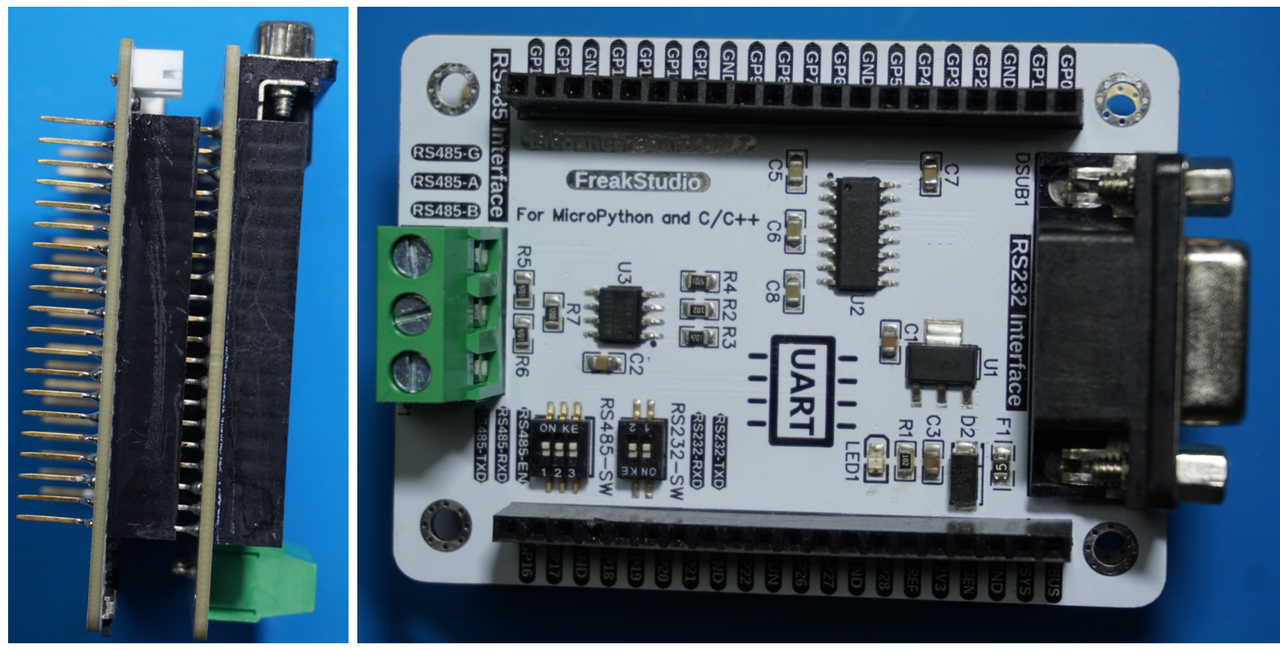
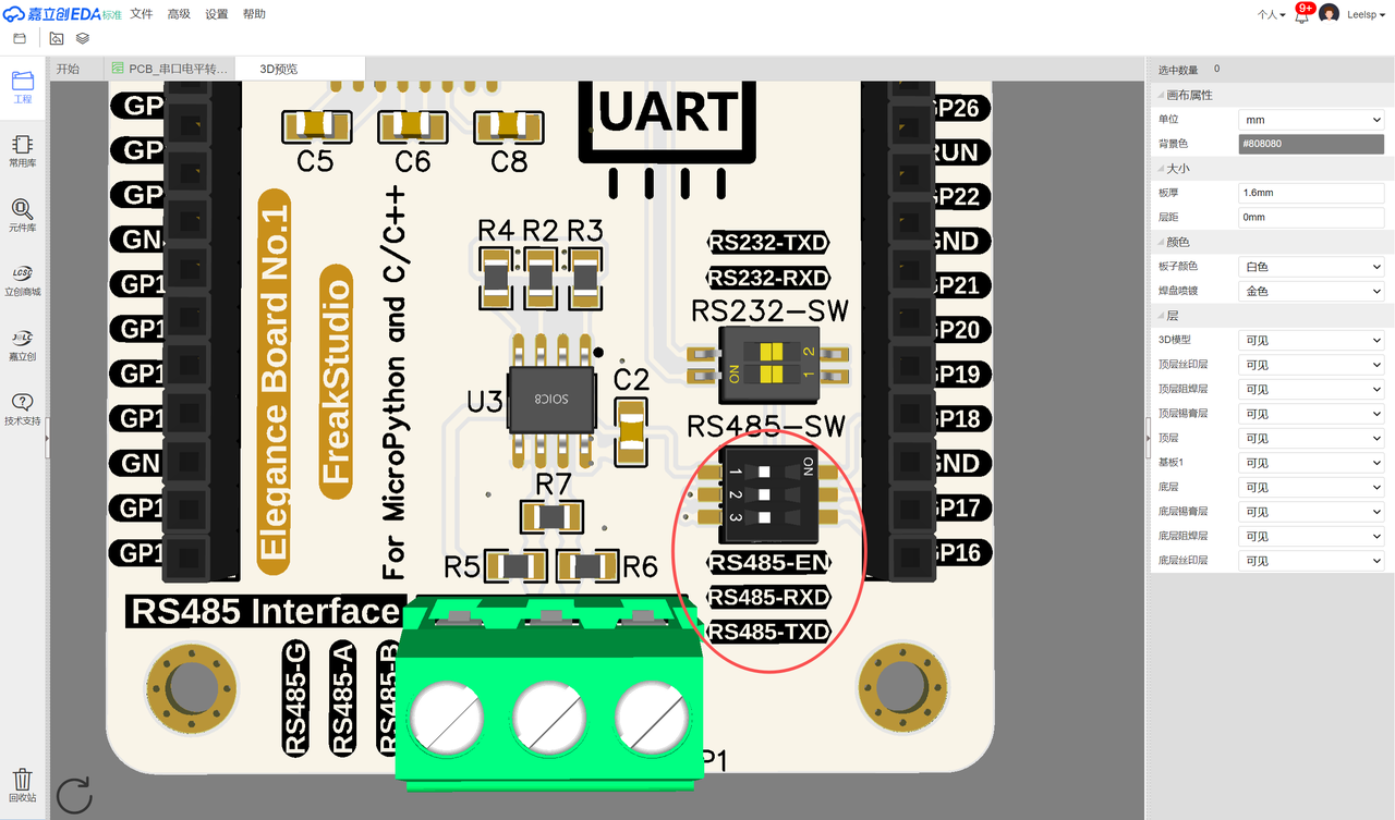
In the following experiment, we need to insert the Fengya No. 1 Board - Grove Interface expansion board into the Fengya No. 1 Board - Serial Port Level Conversion Board, and at the same time turn on the RS485-SW DIP switch RS485-TXD, RS485-RXD and RS485-EN options. We use the serial peripheral 0 to connect with the MAX13487 chip on the Fengya No. 1 Board - Serial Port Level Conversion Board, and set the receiving pin of the Raspberry Pi Pico to GPIO17, and the transmitting pin to GPIO16:
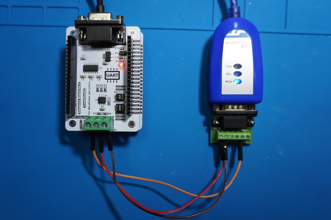
Next, we will Fengya No. 1 Board - Serial Port Level Conversion Board 's RS485 Interface port RS485-A and RS485-B pins to the adapter' s T/R+ and T/R- pins, connect the GND pins of both devices at the same time, and connect the adapter to the computer via the USB port. The physical connection diagram is shown below:
In the following routine, we control the RS485 module to send and receive data via the serial port, and switch the working mode through the transmit-receive control pin to ensure the normal transmission of data streams.
The sample code is as follows, located in the folder of the supporting materials: elegance-devkit v1\Demo\12 UART_RS485:
In the code above, we have customized a RS485Communication class to implement RS485 communication. This class uses the device ID to verify whether the received data is the content sent by itself, and the working principle of its core method is as follows:
When transmitting data, set the control pin to high level to switch the MAX13487 chip to transmit mode; then combine the device ID and data into a message and send it. After the transmission is completed, wait for 100 milliseconds to ensure that the data is sent, and then switch back to receive mode.
When receiving data, decode the received data, split it by lines, iterate through each message, and separate the device ID and message content; if the sender ID does not match the local device ID, print the received message.
Here, the reason why the device ID is used to identify the message source and decode the received data is not only that RS485 communication is usually applied in a master-slave communication scenario with one master and multiple slaves, but also to avoid the echo effect in RS-485 communication, which is an interference caused by signal reflection during transmission. This may lead to the situation that after a device sends RS485 data, it receives the previously sent data when receiving data.
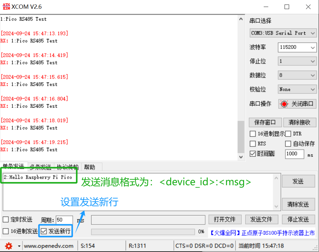
Burn the code, open the terminal, launch the serial port assistant, set it to character display mode, and select "Send New Line" when transmitting data:
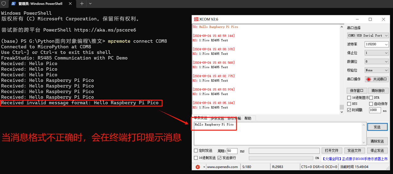
It can be observed that the Raspberry Pi Pico periodically sends data to the computer. When we send data from the computer to the Pico, please note that the format should be as follows:
<设备ID>:<数据内容>\r\n
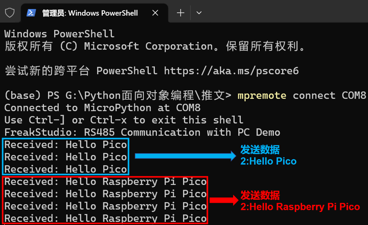
Here, the data we send is: 2: Hello Raspberry Pi Pico.
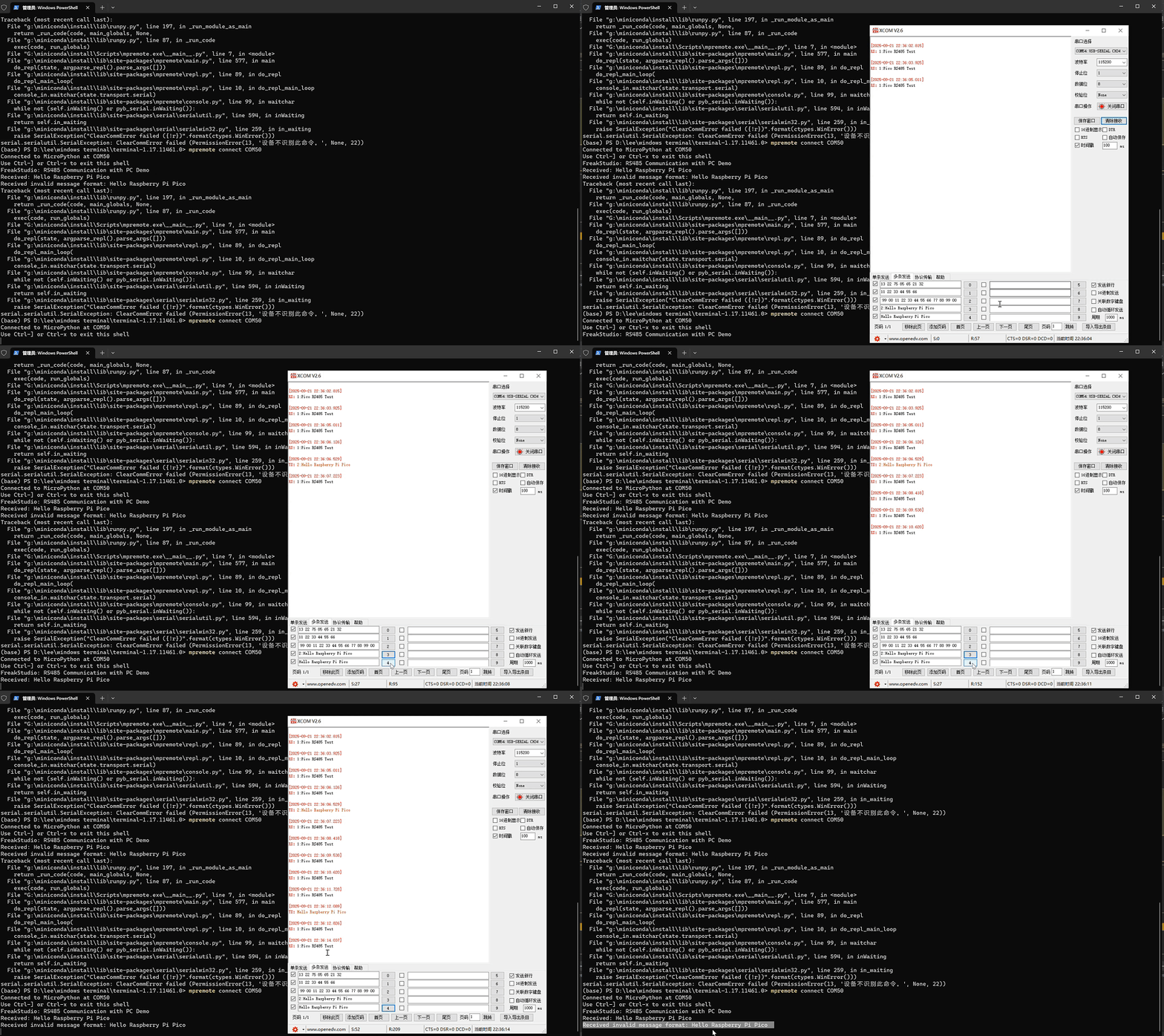
It can be seen that the Raspberry Pi Pico receives successfully. If the format of the data we send is incorrect, the Raspberry Pi Pico will throw an exception and print the corresponding data in the terminal: