MicroPython RS232: XON/XOFF Flow Control & Overflow Solutions
This tutorial introduces RS232 standards, MAX3232 level conversion, and implements an RS232 communication class with XON/XOFF software flow control on Raspberry
COMPONENTS
PROJECT DESCRIPTION
【Preliminary Note】The original hardware example in this article was written based on the RP2040. The actual hardware used in this hands-on demonstration features the W55RP20 as the main controller chip. The circuit logic and UF2 flashing operation principles are universally applicable, with only the main controller model differing. The original chip model mentioned in the circuit descriptions below is provided for reference purposes only.
Tweet
1. Fundamentals of RS232 Communication
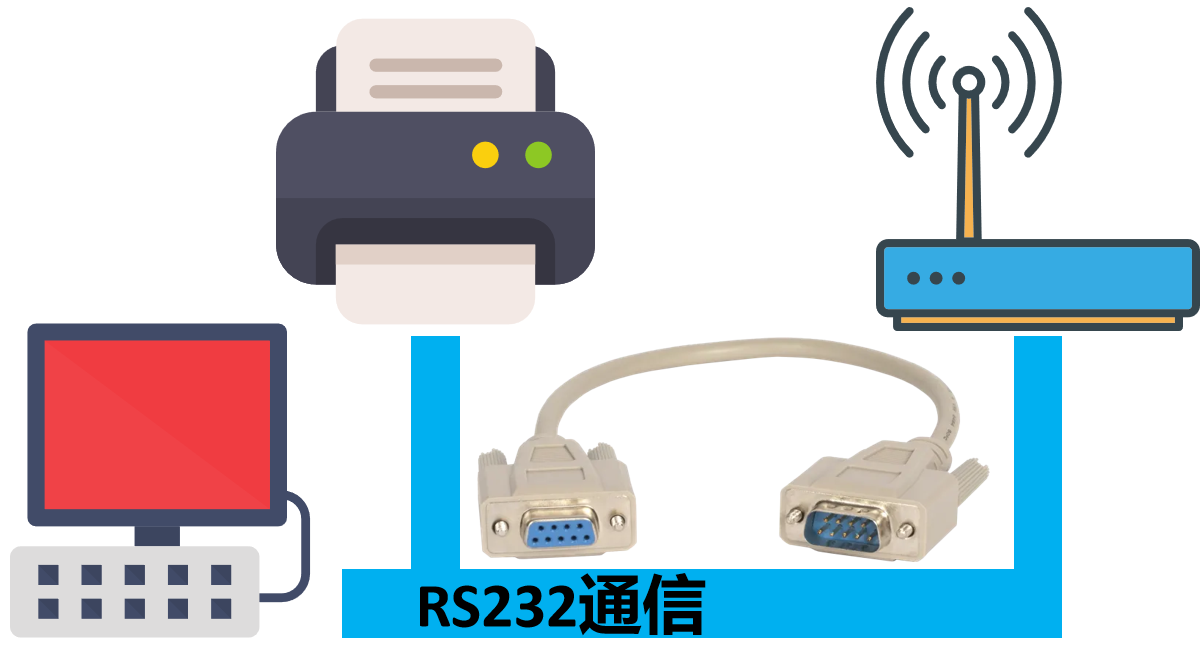
RS-232 is a widely used serial Communication Protocol, originally defined by the Electronic Industries Association (EIA) in the 1960s, which is applied for data transmission between computers and external devices such as modems, printers, sensors and the like.
As we mentioned earlier when discussing the serial port communication protocol layer, the RS-232 standard and the TTL electrical standard we use in serial communication only differ in terms of the logic level standards applied, while they are identical in terms of the specific serial port protocols, including the data packet structure, error detection and correction, as well as rate matching and synchronization for serial communication.
RS-232: It uses high-level and low-level signals. The standard defines the high level as + 3V to + 25V and the low level as -3V to -25V. Due to its relatively high signal level, RS-232 is suitable for long-distance transmission.
TTL-UART: It uses TTL level, where the high level is typically + 2.5V to + 5V (usually 5V) and the low level is 0V; TTL signal level is suitable for short-distance communication.
2. Introduction to MAX3232 Chip
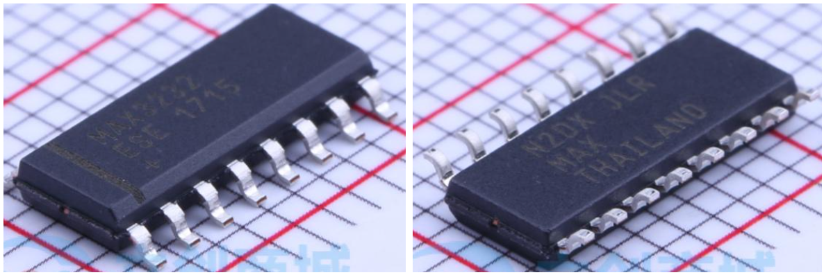
Here, we use the MAX3232 chip to convert TTL level (0V to + 5V) to the RS-232 standard level (±3V to ±25V). The MAX3232 is a commonly used RS-232 to TTL (or CMOS) level converter chip, which supports a data transmission rate of up to 250kbps and two channels of RS-232 to TTL (or CMOS) level conversion, and is often used for serial communication between microcontrollers and devices such as computers, modems, and printers.
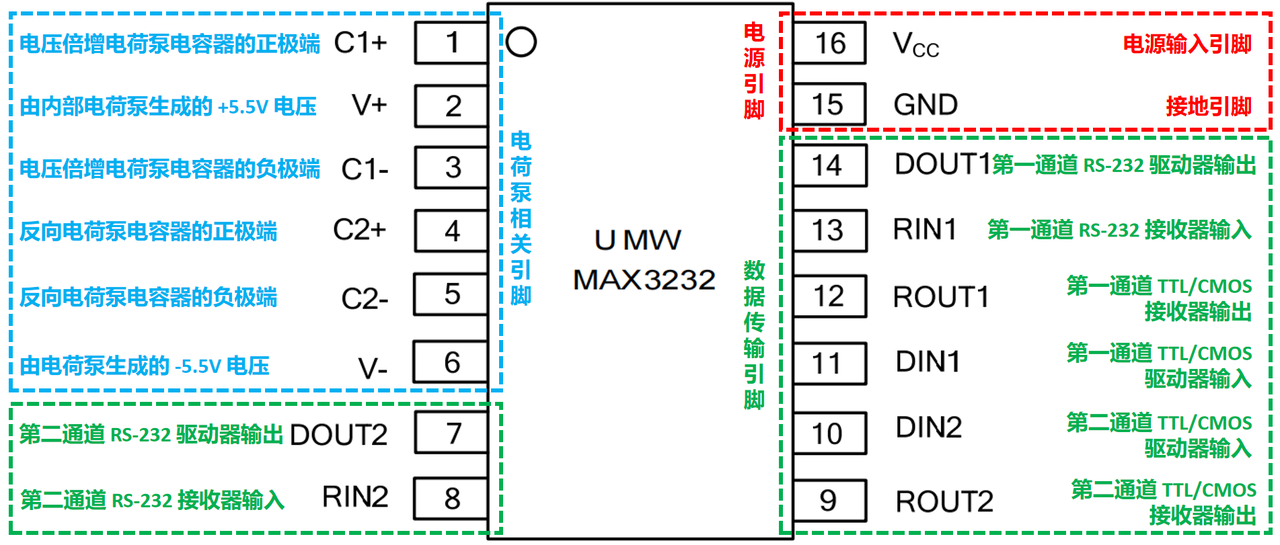
The pin names and functions of the MAX3232 chip are as follows:
They are divided into the following three categories according to their functions:
Charge Pump Related Pins: These pins are used for the operation of the internal charge pump, which generates the required voltages (+ 5.5V and -5.5V) via external capacitors to provide appropriate levels for the RS-232 driver.
Power and Ground Pins: Supply power and ground for the MAX3232 to ensure normal operation of the chip, with a supply voltage range from + 3.0V to + 5.5V.
Data transmission pins: Used for level conversion between TTL/CMOS and RS-232, including RS-232 receiver input and output as well as TTL/CMOS driver input and output.
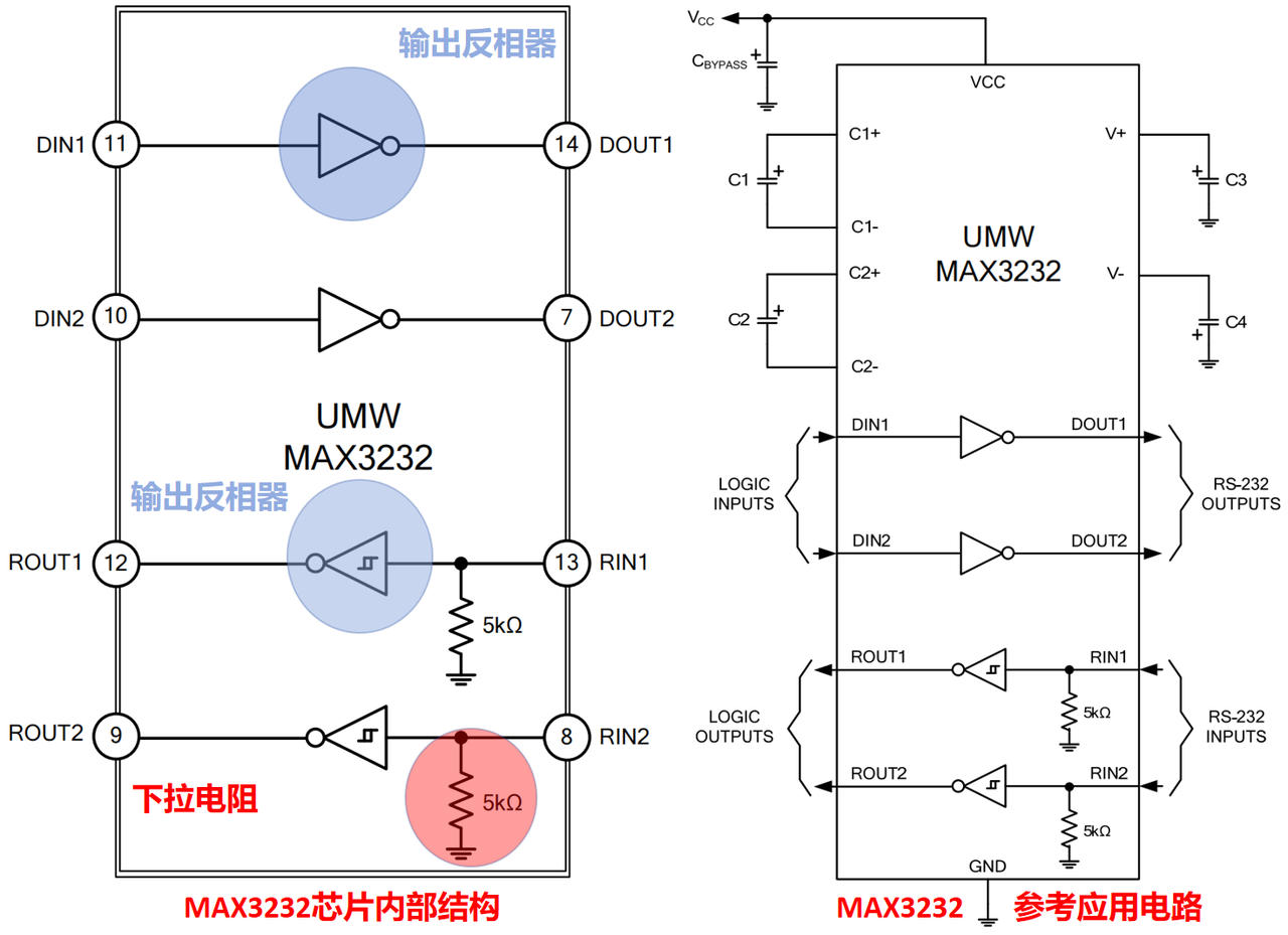
Its working principle can be simply summarized as follows: the MAX3232 converts the input low voltage (e. g., 3.3V or 5V) into high voltages that comply with the RS-232 standard (typically + 5V to + 15V and -5V to -15V) through its built-in charge pump circuit and inverters.
Internal Structure and Reference Circuit of the MAX3232 Chip
Here, the capacitance value required for the operation of the internal charge pump is correlated with the supply voltage:
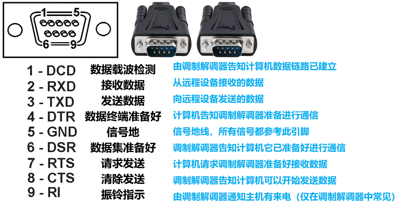
RS-232 communication typically uses DB9 connectors, which feature 9 pins, each serving a specific function in RS-232 communication. The pin numbers and corresponding functions are listed below:
Here, we only use DB9 the RXD, TXD and GND pins of the interface.
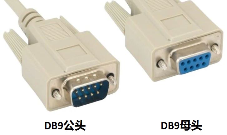
There are two types of DB9 connectors:
Male connector: with 9 protruding metal pins
Female connector: features 9 small holes to receive the pins of the male connector
3. USB to RS232 Adapter
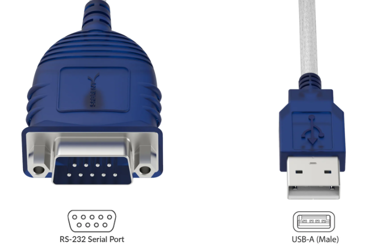
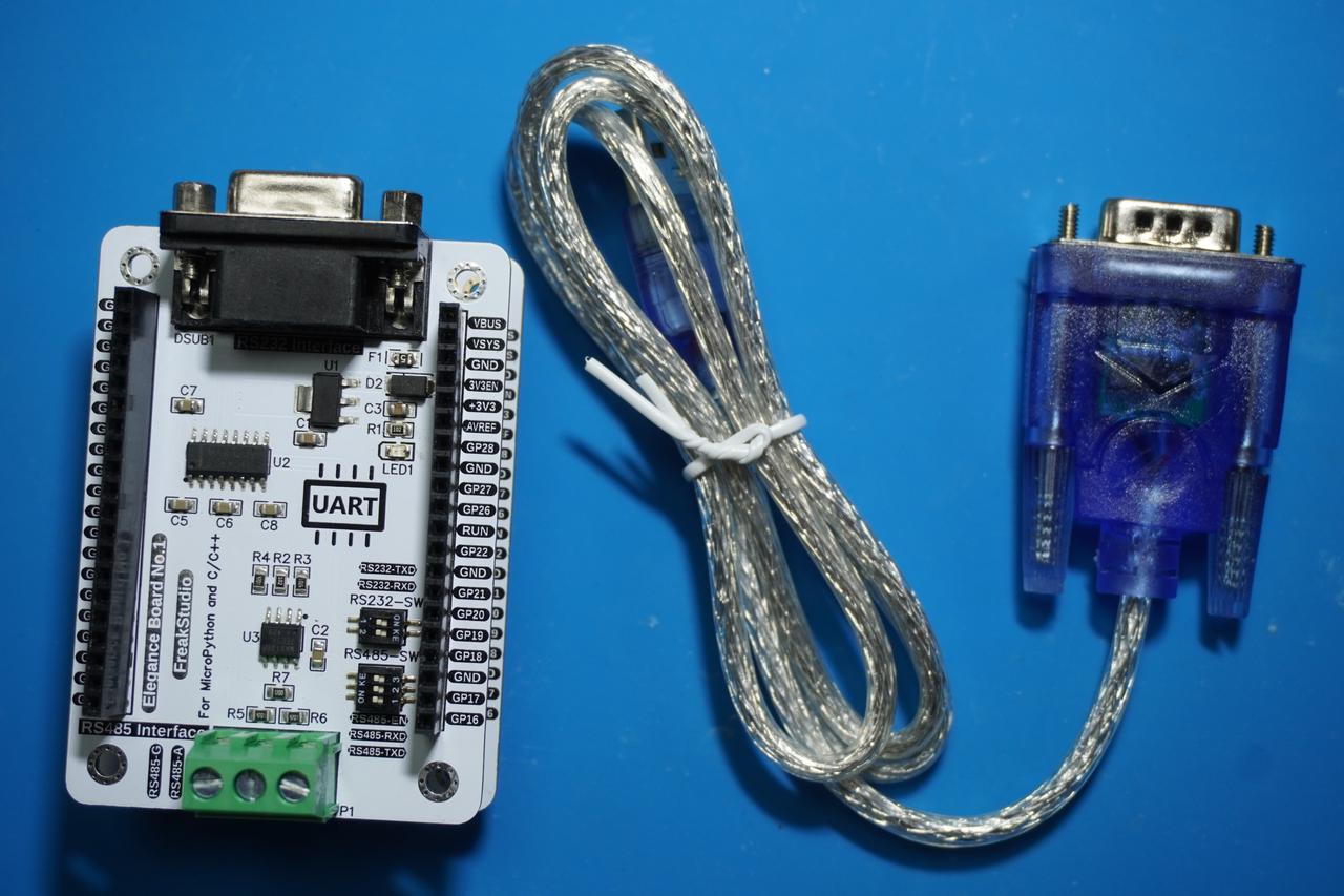
Typically, the serial port of a computer or device uses a DB9 female connector, while one end of a serial cable is a DB9 male connector; the DB9 connector used on our development board is a female type. On modern computers, DB9 connectors have long been phased out, but virtual serial ports (implemented via USB-to-serial conversion) remain functional, and we can use a USB-to-DB9 adapter to enable communication between a microcontroller and a computer over the RS232 protocol.
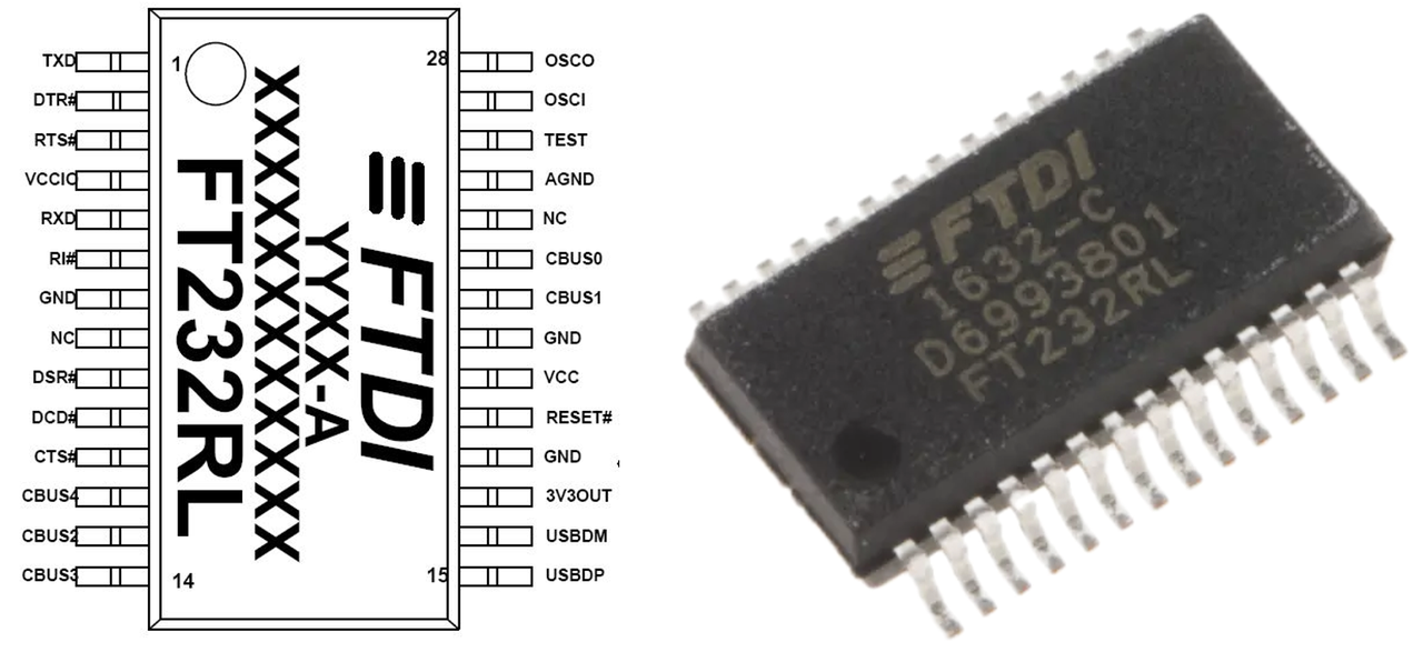
Here, USB-to-RS232 adapters often use a built-in FT232 chip to convert between different Communication Protocols. The FT232 is a USB-to-serial chip designed by FTDI, which is widely used in embedded systems, microcontroller development and debugging, as well as for converting traditional RS-232 or TTL serial interfaces to USB interfaces, enabling modern devices to communicate with legacy serial devices.
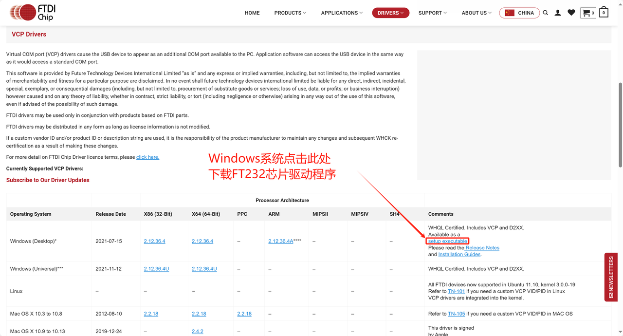
The FT232 chip requires the driver provided by FTDI to be installed in most operating systems, which can be downloaded from FTDI's official website specifically:
https://ftdichip.com/drivers/vcp-drivers/
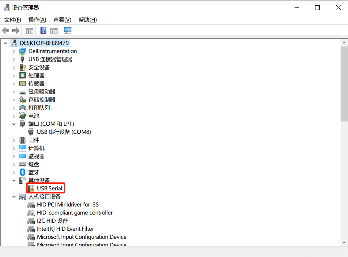
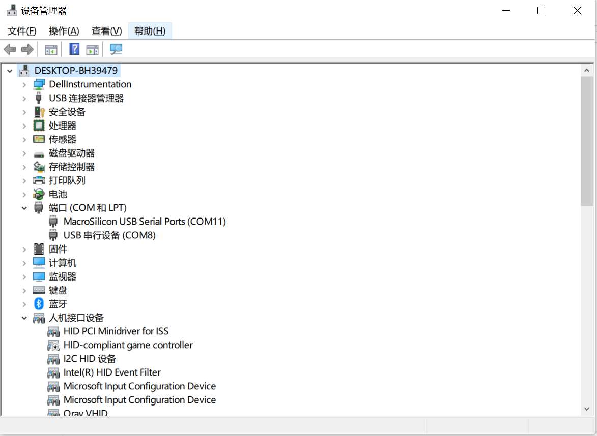
Here, the USB-to-RS232 adapter we provide adopts a domestically produced MS3020 chip, and the corresponding driver program also needs to be installed. If you directly connect the USB-to-RS232 adapter to the computer without installing the corresponding driver, normal communication will not be available. When you open the Device Manager, the display is as follows:
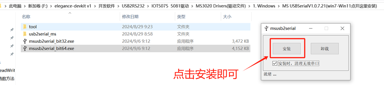
You can also find the corresponding driver in the utility software we provide:
Open the PDF file of the driver installation instructions and follow the steps to complete the installation:
After successful installation, click on the Device Manager again, and you will find that the small exclamation mark on the original device has disappeared, indicating that the device can be used normally. In the corresponding serial communication software assistant, you can also select its port normally:
4. Application Experiment
In the following code, we use a custom RS232 data transceiver class to implement point-to-point communication between the master device (Raspberry Pi Pico) and the slave device (computer), and implement in the custom class software flow control (Software Flow Control) function. The so-called software flow control, also known as XON/XOFF flow control, is a software-based serial communication flow control mechanism. It uses specific control characters to start or stop data transmission. These control characters are sent through the serial communication line without requiring additional physical connections and rely entirely on the serial data line.
Software flow control typically uses the following two ASCII control characters:
XON (0x11, CTRL-Q): indicates "resume data transmission"(the sender may continue transmitting)
XOFF (0x13, CTRL-S): indicates "pause data transmission"(the sender shall suspend transmission to prevent buffer overflow at the receiver end)
So when should these two ASCII control characters be used? Let's briefly explain their application scenarios below:
Receiver sends XOFF: When the receiver's buffer is nearly full, the receiver sends an XOFF signal to notify the sender to pause data transmission
Sender Pauses Transmission: Upon receiving the XOFF signal, the sender immediately pauses data transmission and waits for further instructions
Receiver sends XON: When the receiver finishes processing the data and frees up buffer space, it will send an XON signal to inform the sender that it can resume data transmission
The sender continues transmission: After receiving the XON signal, the sender resumes data transmission until it receives another XOFF signal or completes data transmission
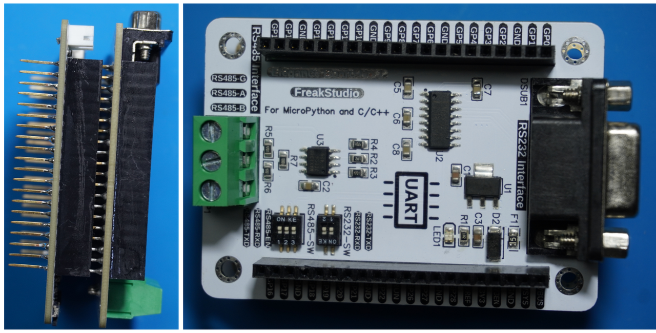
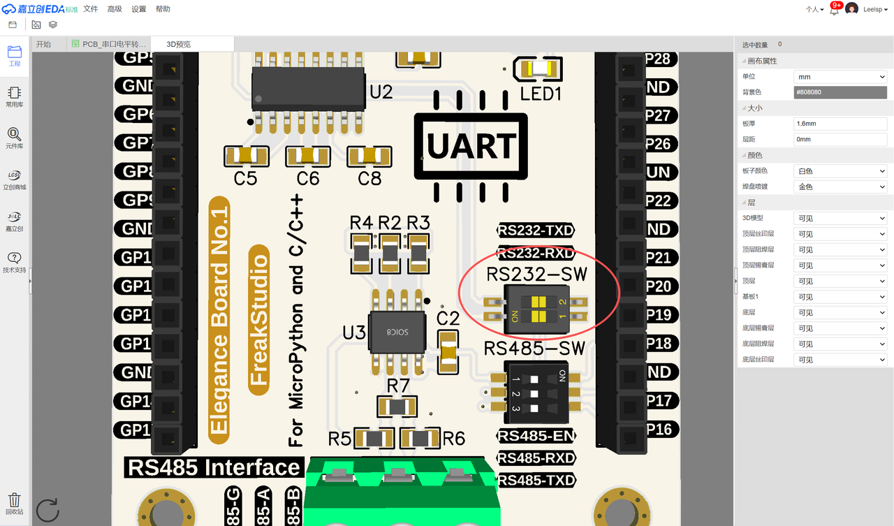
In the following experiment, we need to insert the Fengya No. 1 Board - Grove Interface expansion board into the Fengya No. 1 Board - Serial Port Level Conversion Board, and at the same time turn on the RS232-SW DIP switch RS232-TXD and RS232-RXD options. We use the serial peripheral 0 to connect to the TTL1 interface of the RS232 chip on the Fengya No. 1 Board - Serial Port Level Conversion Board, and set the receive pin of the Raspberry Pi Pico to GPIO17, and the transmit pin to GPIO16:
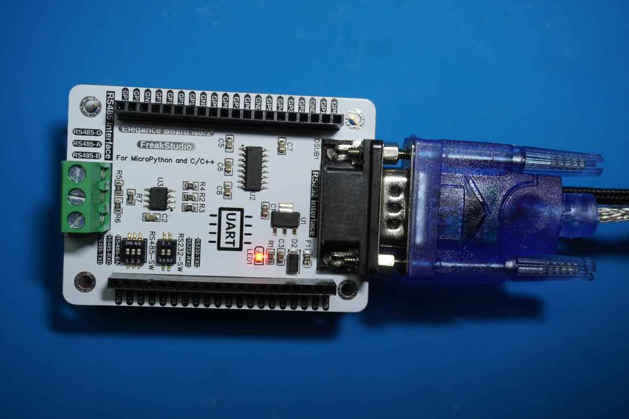
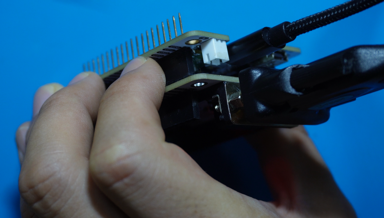
Next, we use a USB-to-RS232 adapter to connect to Fengya No. 1 Board - Serial Port Level Conversion Board 's RS232 Interface port, and the physical connection diagram is shown below:
We first customize an RS232 communication class with software flow control function, and the sample code is as follows:
Send data send (): First check whether data is a string; if not, convert it to a string, encode the data into a UTF-8 byte string, and store it in the transmit buffer tx_buffer; then send the data byte by byte. Before each data transmission, check the xon status; if xon is False (i. e., an XOFF signal has been received), pause transmission until an XON signal is received; after the data is sent, reset the transmit buffer pointer tx_pos to 0
Receive data receive (): Check whether there is received data via self. uart. any () and read the data one by one; then perform XON/XOFF signal detection and received data storage. If the receive buffer is full (i. e. rx_pos is equal to or exceeds rx_buf_size), send an XOFF signal to the sender to notify it to suspend data transmission, finally return all received data and reset the receive buffer pointer rx_pos
The complete code is shown below, located in the folder of the supporting materials: elegance-devkit v1\Demo\11 UART_RS232:
Here, in the main loop, we use the data transmission method in the custom class to send data at regular intervals of approximately 1 second. The timer checks for incoming data every 10 milliseconds; if any data is received, it will be output to the terminal, and the LED will indicate the current flow control status of the serial port.
Here, the timer can be simply understood as an execution flow that periodically executes the corresponding callback function receive_data. It is triggered periodically, will call a certain function at set time intervals and is not affected by the time. sleep delay method. In this program, through the periodic call of the timer, we can realize continuous monitoring of serial port data.
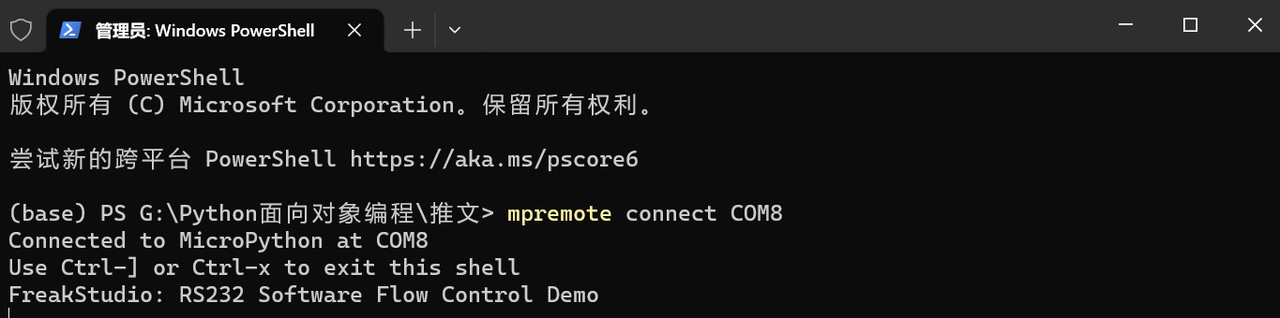
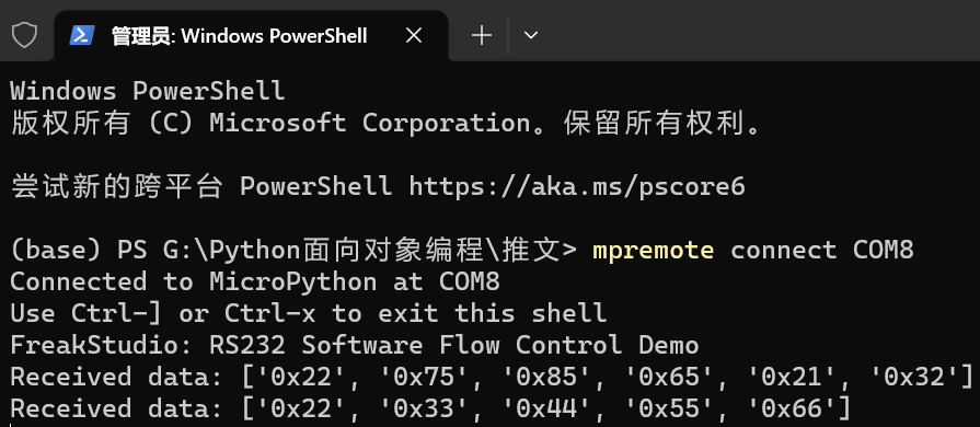
Burn the code, open the terminal, and the following content will be displayed:
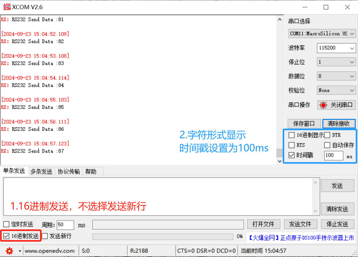
Open the serial port assistant and set the baud rate to 115200, keep other parameters as default, then select the COM port corresponding to the following name:
MacroSilicon USB Serial Ports
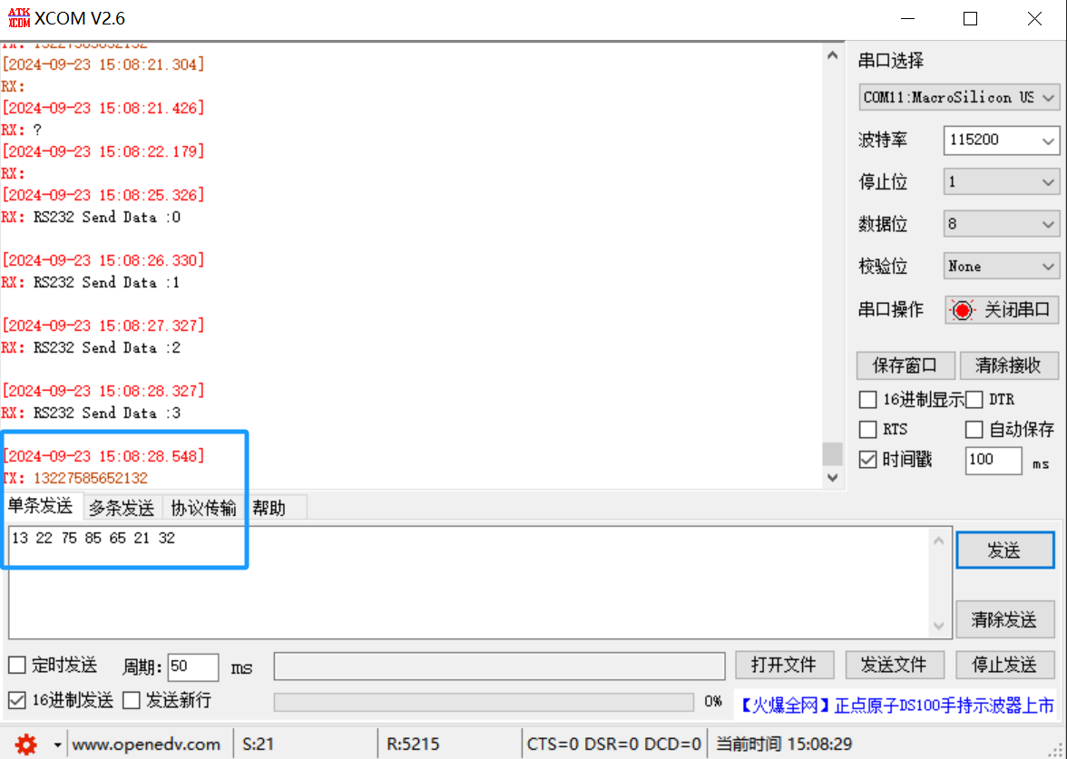
Here, when using the serial port assistant for communication, please note that the display should be in character format, the transmission should be in hexadecimal format, and do not select the "Send New Line" option.
It can be seen that the custom RS232 communication class is configured to send data at a timer interval of 1 second. Let's try sending hexadecimal data:
13 22 75 85 65 21 32
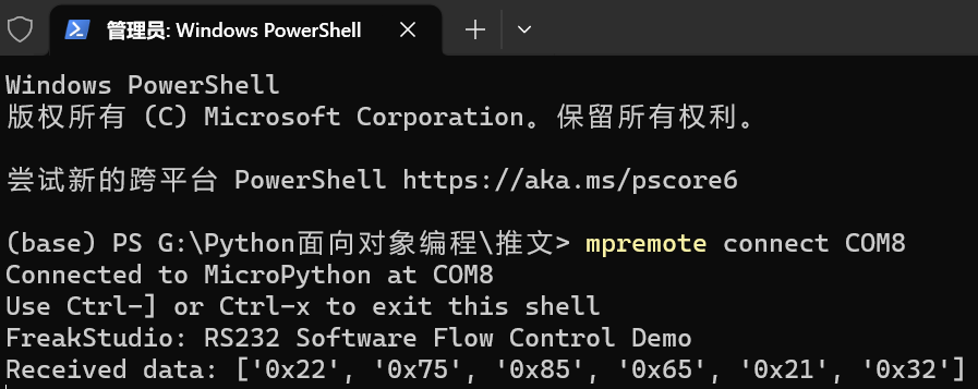
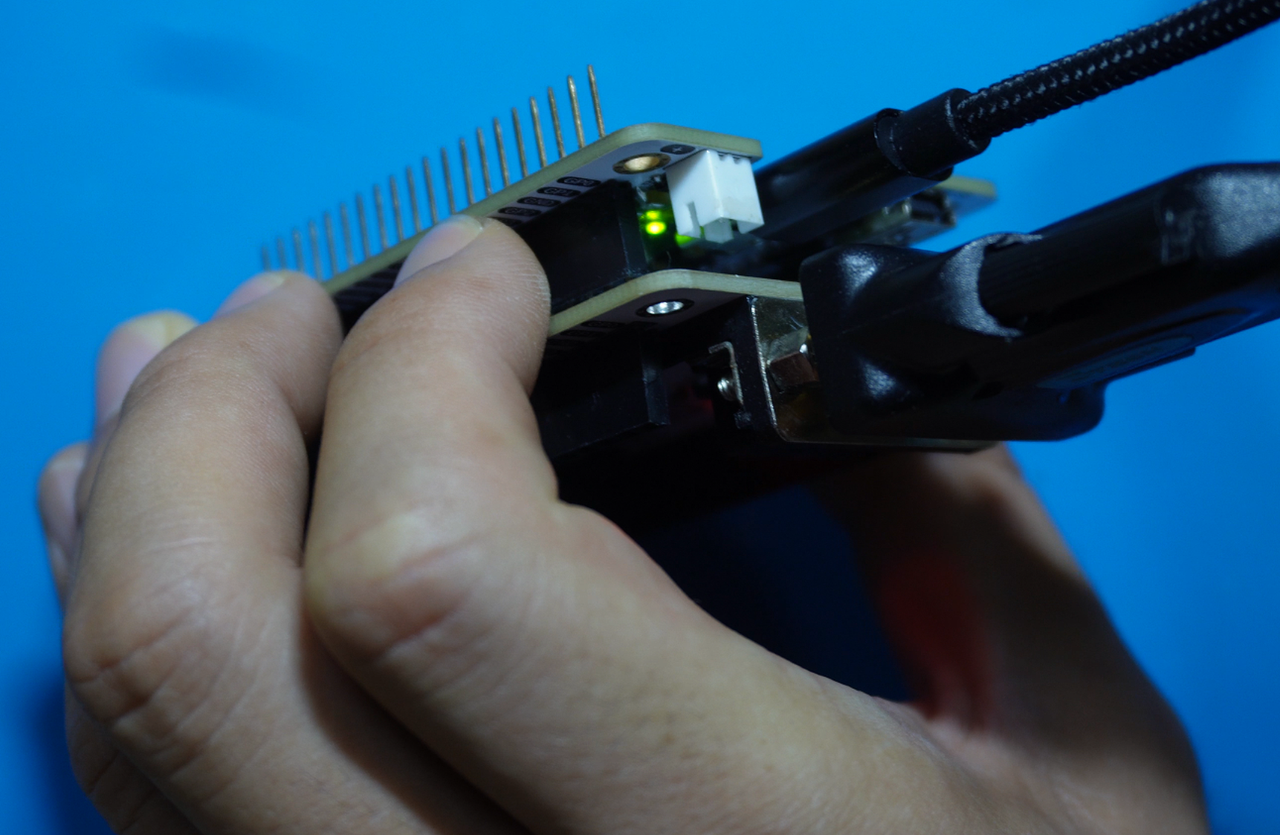
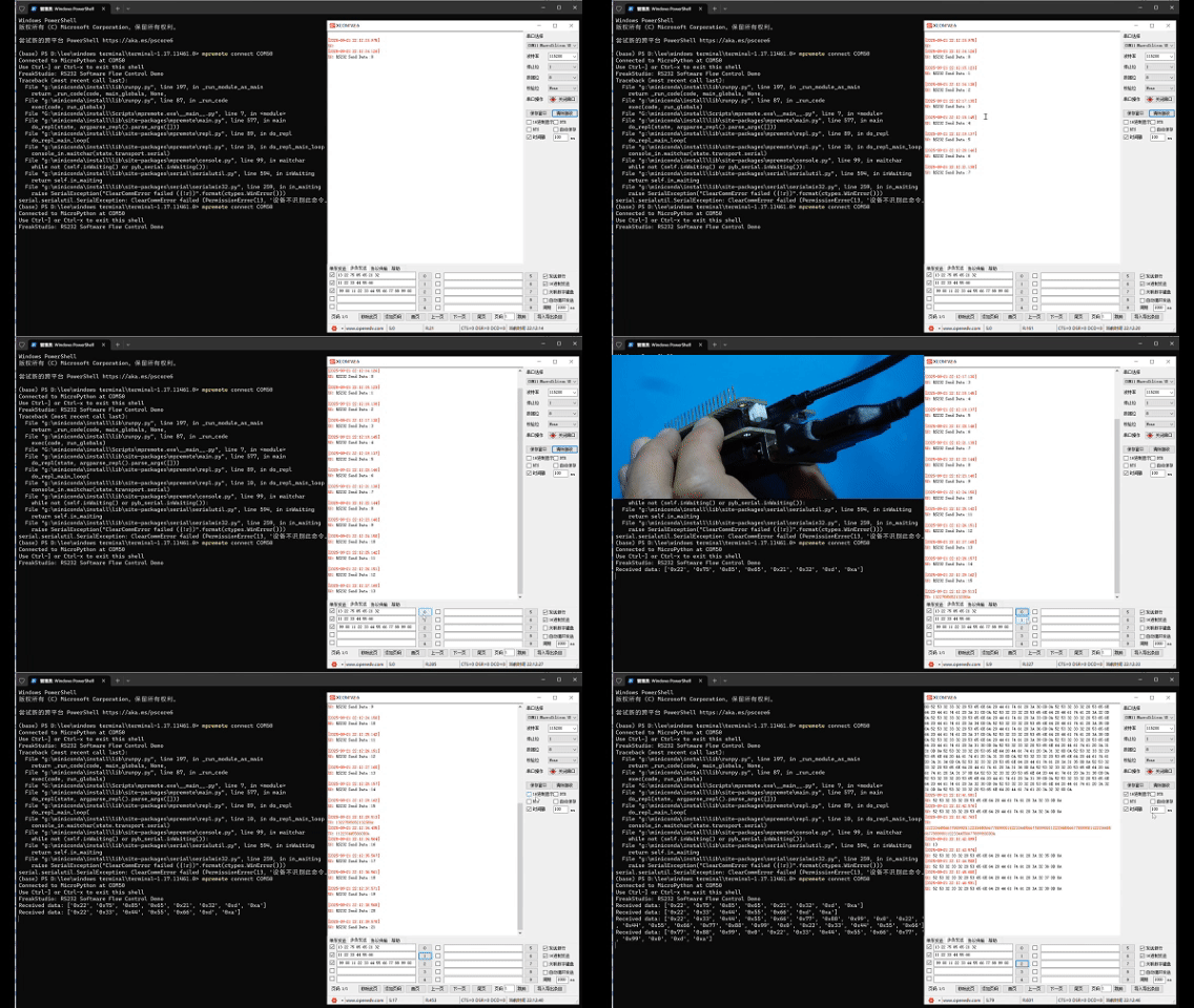
As can be seen, all data except the flow control character XOFF (0x13) is displayed on the terminal. Meanwhile, on the serial port assistant software, you can observe that the Raspberry Pi Pico has stopped sending data, and the onboard LED on the Raspberry Pi Pico is lit up:
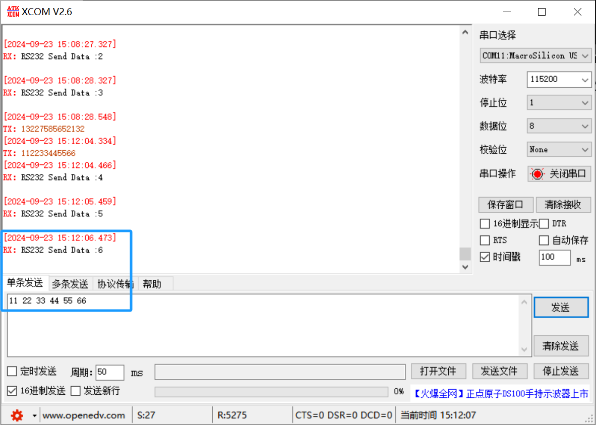
Resend data: 11 22 33 44 55 66, in which XON (0x11) flow control character indicates that the PC side is ready to receive data:
It can be found that at this point, the RS232 communication of the Raspberry Pi Pico restarts, and the onboard LED turns off at the same time:
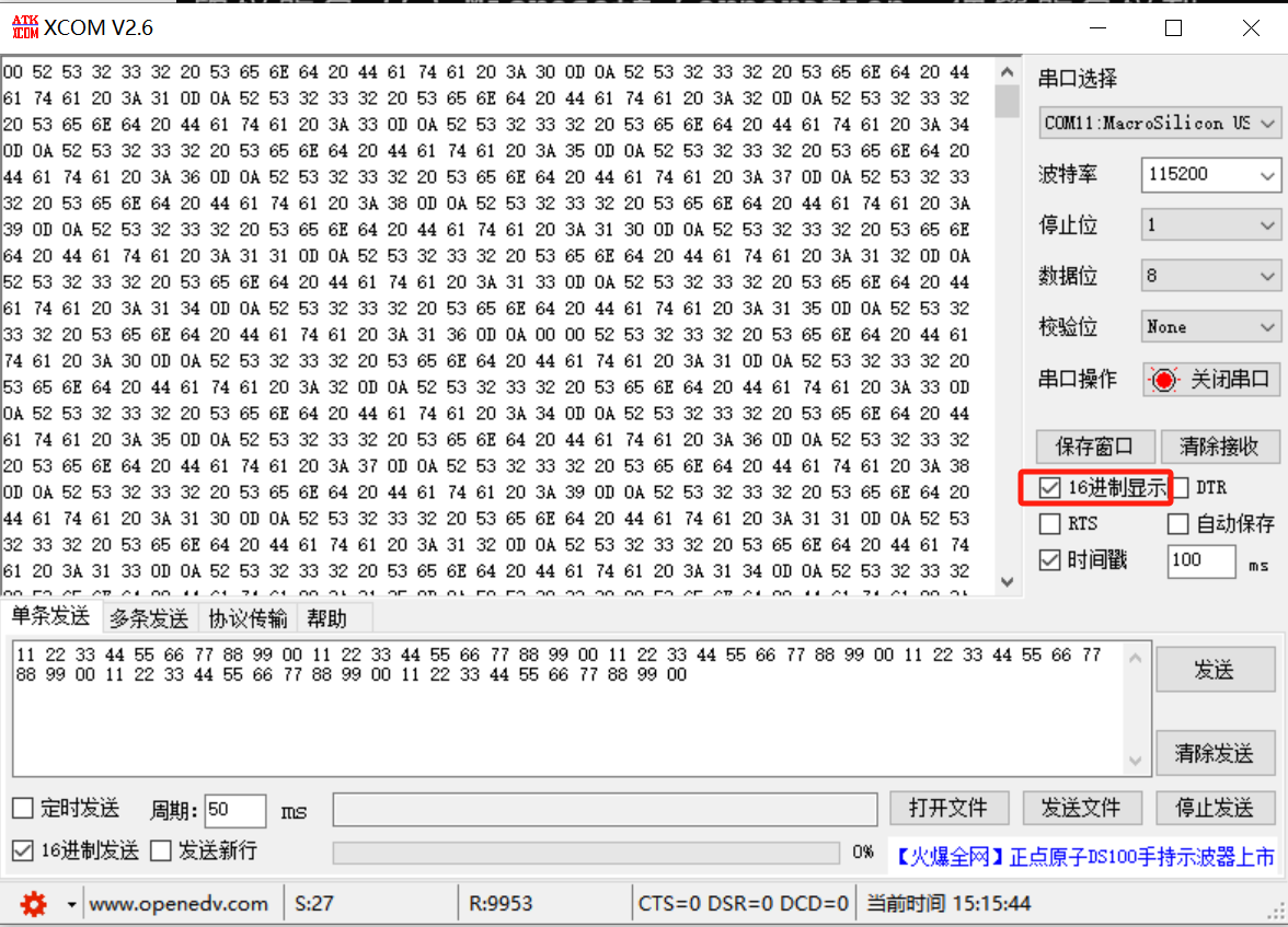
Here, we will send a hexadecimal data whose length exceeds the set data buffer:
And set in advance that the serial port assistant displays in hexadecimal format:
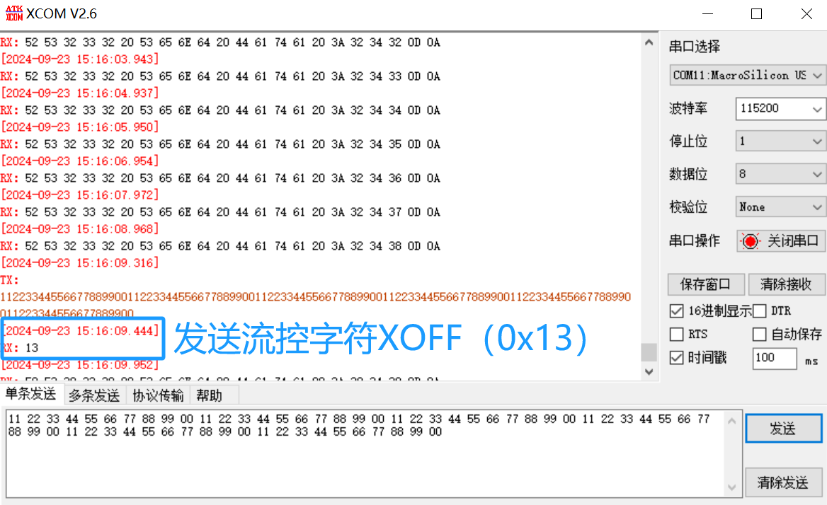
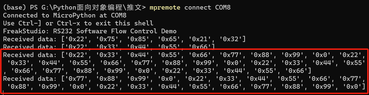
Then send the data, and you can see that the Raspberry Pi Pico has sent the flow control character XOFF (0x13):
Furthermore, the size of the data received by the Raspberry Pi Pico never exceeds the set buffer size:
From the above tests, it can be seen that our custom RS232 software flow control communication class can implement the basic functions of transmission interruption and resumption. Compared with hardware flow control, software flow control is simple and easy to use without requiring extra wiring, but it also has certain drawbacks: it relies on special control characters to manage data transmission, which will occupy part of the transmission bandwidth. Meanwhile, XON (0x11) and XOFF (0x13) are specific control characters; however, if the transmitted data itself contains these characters, they may be misinterpreted as flow control commands, thus triggering erroneous transmission pauses or resumptions.