MicroPython PIO API Deep‑Dive: StateMachine & PIO Class Methods
MicroPython uses rp2 module to configure and run RP2040 PIO state‑machines.
COMPONENTS
PROJECT DESCRIPTION
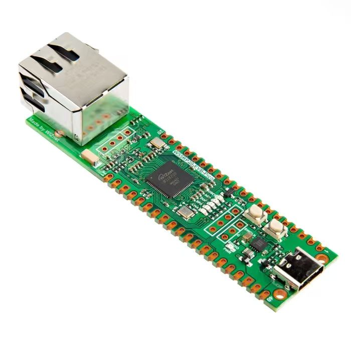
【Preliminary Note】The original hardware example in this article was written based on the RP2040. The actual hardware used in this hands-on demonstration features the W55RP20 as the main controller chip. The circuit logic and UF2 flashing operation principles are universally applicable, with only the main controller model differing. The original chip model mentioned in the circuit descriptions below is provided for reference purposes only.
Tweet:
Software Control Method
When controlling the PIO of Raspberry Pi Pico via MicroPython, you need to use the @rp2. asm_pio decorator, as well as the PIO class and the StateMachine class:
The pioasm assembler is written within the @rp2. asm_pio decorator function, and the GPIO pin mapping to be used, whether to enable automatic push and automatic pull, FIFO merging and other related configurations are also specified in the rp2. asm_pio class.
Configure a finite-state machine instance via the StateMachine class to run a given PIO program; meanwhile, the StateMachine class also provides control methods and status reading methods for the finite-state machine.
1. Construction method of rp2. StateMachine class
The constructor of the rp2. StateMachine class is as follows:
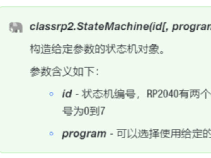
classrp2.StateMachine(id[, program, ...])
Construct a finite-state machine object with the given parameters.
The parameters are defined as follows:
id - finite-state machine number. The RP2040 has two identical PIO instances, and each instance has 4 finite-state machines: so there are a total of 8 finite-state machines, numbered from 0 to 7
program - you can choose to initialize it with a given program
2. Other methods of the rp2. StateMachine class
The rp2. StateMachine class also features methods such as an initialization method, methods for setting or retrieving the running configuration, and a restart method:
Configure the finite-state machine instance to run the given program.
This program is added to the instruction memory of this PIO instance. If the instruction memory already contains this program, its offset is reused to save instruction memory space.
The parameters are defined as follows:
freq - is the frequency at which the finite-state machine operates, measured in hertz. It defaults to the system clock frequency.
in_base - is the first pin used for the in () instruction
out_base - is the first pin for the out () instruction
set_base - is the first pin for the set () instruction
jmp_pin - is the first pin used for the jmp (pin, . ..) instruction
sideset_base - is the first pin used for sideset operations
in_shiftdir - indicates the direction in which the ISR will shift, either PIO. SHIFT_LEFT or PIO. SHIFT_RIGHT
out_shiftdir - specifies the direction in which the OSR will shift, either PIO. SHIFT_LEFT or PIO. SHIFT_RIGHT
push_thresh - is the shift count threshold before triggering automatic push or conditional re-push
pull_thresh - is the shift count threshold before triggering automatic push or conditional re-push
StateMachine.active([value])
Gets or sets whether the finite-state machine is currently running.
The parameters are defined as follows:
When setting a value, the finite-state machine will be started or stopped according to the value: if the value is 1, the finite-state machine will be started; otherwise, it will be stopped.
If no value is set, obtain the start-stop status of the finite-state machine
StateMachine.restart()
Restart the finite-state machine and jump to the start of the program
This method uses the SM_RESTART register of the RP2040 to clear the internal state of the finite-state machine, which includes:
Input and output shift counter
Contents of the input shift register
Delay Counter
Waiting for IRQ status
Stop instruction executed via StateMachine. exec ()
StateMachine.exec(instr)
Execute a single PIO instruction.
The parameters are defined as follows:
instr - Instruction in the instruction register:
If instr is a string, use asm_pio_encode to encode the instructions in the given string
If instr is an integer, it is treated as an encoded PIO machine code instruction to be executed
StateMachine.get(buf=None, shift=0)
Reads one byte of data from the RX FIFO of the finite-state machine; if the FIFO is empty, it will block until data arrives.
The parameters are defined as follows:
buf - A Buffer Protocol-compliant buffer object that stores the read byte data
shift - number of bits to shift right, the return value is word>>shift
StateMachine.put(value, shift=0)
Write data to the TX FIFO of the finite-state machine; if the FIFO is full or becomes full, this method will block until the finite-state machine has transmitted enough words to complete the write operation.
The parameters are defined as follows:
value - the data to be written, which can be an integer, an array of type B, H or I, or a byte array
shift - number of bits to shift left; the data to be written equals word << shift
StateMachine.rx_fifo()
Returns the number of data bytes available in the RX FIFO of the finite-state machine; a value of 0 indicates that the FIFO is empty.
It is very useful for checking whether data is waiting to be read before calling StateMachine. get ().
StateMachine.tx_fifo()
Returns the number of data bytes available in the TX FIFO of the finite-state machine; a value of 0 indicates that the FIFO is empty.
It is very useful for checking whether there is available space for data writing before invoking StateMachine. put ().
StateMachine.irq
(handler=None, trigger=0 | 1, hard=False)
Returns the IRQ object of the given StateMachine, which can be optionally configured.
3. rp2. Constructor of the PIO class
The constructor of the rp2. PIO class is as follows:
class rp2.PIO(id)
Construct a PIO object with the given parameters.
The parameters are defined as follows:
id - PIO peripheral number. The RP2040 has two identical PIO instances: PIO0 and PIO1
4. Other Methods of rp2. PIO Class
Method
Description
PIO.add_program(program)
Add the program to the instruction memory of this PIO instance.
The amount of memory available for programs on each PIO instance is limited. If there is not enough space in the program memory of the PIO, this method will raise an OSError (ENOMEM).
PIO.remove_program([program])
Delete the program from the instruction memory of this PIO instance.
If no program is provided, all programs will be deleted.
Deleting an already deleted program will not trigger an error.
PIO.state_machine(id[, program, ...])
Obtain the finite-state machine number id.
On the RP2040, each PIO instance has 4 finite-state machines, numbered 0 to 3.
MicroPython only uses IRQ 0 on each PIO instance; IRQ 1 is not available.
You can choose to configure it.
5. Function for Assembling PIO Assembly Programs
There are three functions for assembling PIO assembly programs:
Method
Description
rp2.asm_pio
(*, out_init=None, set_init=None,
sideset_init=None, in_shiftdir=0,
out_shiftdir=0, autopush=False,
autopull=False, push_thresh=32,
pull_thresh=32,
fifo_join=PIO.JOIN_NONE)
Assemble a PIO program.
The parameters are defined as follows:
out_init - Configure the pins for the out () instruction
set_init - Configure the pins for the set () instruction, up to 5 pins are allowed
sideset_init - Configure the pins for sideset operations, with a maximum of 5 pins available
You can configure the pins using the following parameters:
PIO.IN_LOW
PIO.IN_HIGH
PIO.OUT_LOW
PIO.OUT_HIGH
in_shiftdir - specifies the default shift direction for ISR, which can be either PIO. SHIFT_LEFT or PIO. SHIFT_RIGHT
out_shiftdir - the default direction for OSR shifting, which can be either PIO. SHIFT_LEFT or PIO. SHIFT_RIGHT
push_thresh - is the shift count threshold before triggering automatic push or conditional re-push
pull_thresh - the shift count threshold before triggering automatic push or conditional re-push
autopush - Configure whether to enable automatic push
autopull - Configure whether to enable automatic loading
fifo_join - Configure whether to merge the 4-word TX and RX FIFOs into a single 8-word FIFO in only one direction:
PIO. JOIN_NONE - Do not merge the two FIFOs
PIO. JOIN_RX - Combine two FIFOs into a single RX FIFO
PIO. JOIN_TX - Merge two FIFOs into a single TX FIFO
rp2.asm_pio_encode
(instr, sideset_count, sideset_opt=False)
Assemble a single PIO instruction.
The parameters are defined as follows:
instr - Single PIO Instruction
sideset_count - number of bits for side set operation
sideset_opt-Whether to use the opt option
rp2.bootsel_button()
Temporarily configure the QSPI_SS pin as an input and read its value; a return value of 1 indicates a low level, while 0 indicates a high level.
On a typical RP2040 board with a BOOTSEL button, a return value of 1 indicates that the button is pressed.
Since this function temporarily disables access to external flash memory, it also temporarily disables interrupts and other cores to prevent them from attempting to execute code from the flash memory.
In addition, if an error occurs when assembling a PIO program, rp2. PIOASMError will be raised from asm_pio () or asm_pio_encode (), and the class rp2. PIOASMError is an exception class dedicated to PIO.
6. PIO Instructions in MicroPython
In MicroPython, PIO assembly routines are written as Python functions decorated with @rp2. asm_pio (), and they use Python syntax. Such routines support standard Python variables and arithmetic, as well as the following custom functions that encode PIO instructions and guide the assembler.
Instruction
Description
wrap_target()
Specifies the position where the program resumes execution after a return. By default, this is the start of the PIO routine.
wrap()
Specifies the position where the program ends and returns. If this instruction is not used, it will be automatically added to the end of the PIO routine.
Loopback does not consume any execution cycles.
label(label)
Define a label named label at the current position. The label can be a string or an integer.
word(instr, label=None)
Insert an arbitrary 16-bit word in the assembly output; the meaning of the parameters is as follows:
instr: 16-bit value
label: If specified, use instr to find the value of the label and logical OR label
jmp(…)
This instruction has two forms:
jmp(label)
label: the label to jump to unconditionally
jmp(cond, label)
cond: the condition to be checked, including
not_x, not_y: true if the register is zero
x_dec, y_dec: true if the register is non-zero, and post-decrement is performed
x_not_y: Returns true if X is not equal to Y
pin: true if the input pin is set
not_osre: true if OSR is not empty (i. e., its threshold has not been reached)
label: the label to jump to if the condition is true
wait(polarity, src, index)
Blocking delay, waiting for a high/low level on the pin or IRQ line.
polarity: 0 or 1, indicating whether to wait for a low value or a high value
src: one of the following: gpio - absolute pin number, pin - pin relative to the in_base parameter of StateMachine, irq
index: 0-31, the index of src
in_(src, bit_count)
Move the data from src to the ISR.
src: one of the following: pin, x, y, null, isr, osr
bit_count: Number of bits to be shifted in (1-32)
out(dest, bit_count)
Move the data from the OSR to the target.
dest: one of the following: pin, x, y, pindirs, pc, isr, exec
bit_count: Number of bits to shift out (1-32)
push(…)
Push the ISR into the RX FIFO, then clear the ISR. This instruction takes the following form:
push()
push(block)
push(noblock)
push(iffull)
push(iffull, block)
push(iffull, noblock)
If block is used, the instruction will block and pause when the RX FIFO is full. The default is block.
If iffull is used, the push operation will only be triggered when the input shift counter reaches its threshold.
pull(…)
Pull OSR from TX FIFO. This instruction takes the following form:
pull()
pull(block)
pull(noblock)
pull(ifempty)
pull(ifempty, block)
pull(ifempty, noblock)
If block is used, the instruction will stop when the TX FIFO is empty; block is the default setting.
If ifempty is used, the fetch operation will only be performed when the output shift counter reaches its threshold.
mov (dest, src)
Move the value from src to dest.
dest: one of the following: pin, x, y, exec, pc, isr, osr
src: one of the following: pin, x, y, null, status, isr, osr; this parameter can be selectively modified by wrapping it in invert () or reverse ()(but not both at the same time)
irq(…)
Set or clear the IRQ flag. This instruction has two forms:
irq(index)
index: 0-7, or rel (0) to rel (7)
irq(mode, index)
index: 0-7, or rel (0) to rel (7)
mode: block 或 clear
If block is used, the instruction will stop until the flag is cleared by another object.
If clear is used, the flag will be cleared instead of being set.
The relative IRQ index is obtained by adding the finite-state machine ID to the IRQ index via modulo-4 addition.
IRQ 0-3 are visible to the processor, while 4-7 are internal to the finite-state machine.
set(dest, data)
Set dest using the value.
dest: pins, x register, y register, pindirs
data: a value ranging from 0 to 31
nop()
This is a pseudo-instruction assembled as mov (y, y), which has no side effects.
.side(value)
A modifier used to control the value of the side set pin, which can be applied to any instruction.
value: the value (bit) to be output on the side set pin
.delay(value)
This is a modifier that can be applied to any instruction to specify how many cycles to delay after the instruction is executed.
value: delay cycle, ranging from 0 to 31 (the maximum value will be reduced if the side-set pin is used)