MicroPython + MCP4725 Signal‑Generator: Custom Class Full Project Workflow
End‑to‑end MCP4725 signal‑generator project workflow
- Custom MCP4725 Class
Below is a custom driver class for the MCP4725 chip.
# Python env   : MicroPython v1.23.0
# -*- coding: utf-8 -*-
# @Time    : 2024/9/1 2:10 PM
# @Author  : Li Qingshui
# @File    : mcp4725.py
# @Description : 12‑bit DAC chip MCP4725 driver module
# Reference code: https://github.com/wayoda/micropython-mcp4725/blob/master/mcp4725.py
# ======================================== Import related modules =========================================
# Import hardware‑related modules
from machine import I2C
# ======================================== Global variables ============================================
# ======================================== Function definitions ============================================
# ======================================== Custom classes ============================================
# Custom DAC chip MCP4725 class
class MCP4725:
    """
    MCP4725 class for controlling the MCP4725 Digital‑to‑Analog Converter chip. Communicates with host MCU over I2C interface and outputs analog voltage values.
    Attributes:
        i2c (machine.I2C): I2C interface object used to communicate with MCP4725.
        address (int): I2C address of MCP4725, default 0x60.
        _writeBuffer (bytearray): Data buffer for values to be written to DAC.
    Class Variables:
        BUS_ADDRESS (list): Possible I2C addresses for MCP4725, default [0x60, 0x61, 0x62, 0x63, 0x64, 0x65, 0x66, 0x67].
        POWER_DOWN_MODE (dict): Power‑down mode mapping dictionary containing 'Off', '1k', '100k', '500k' modes.
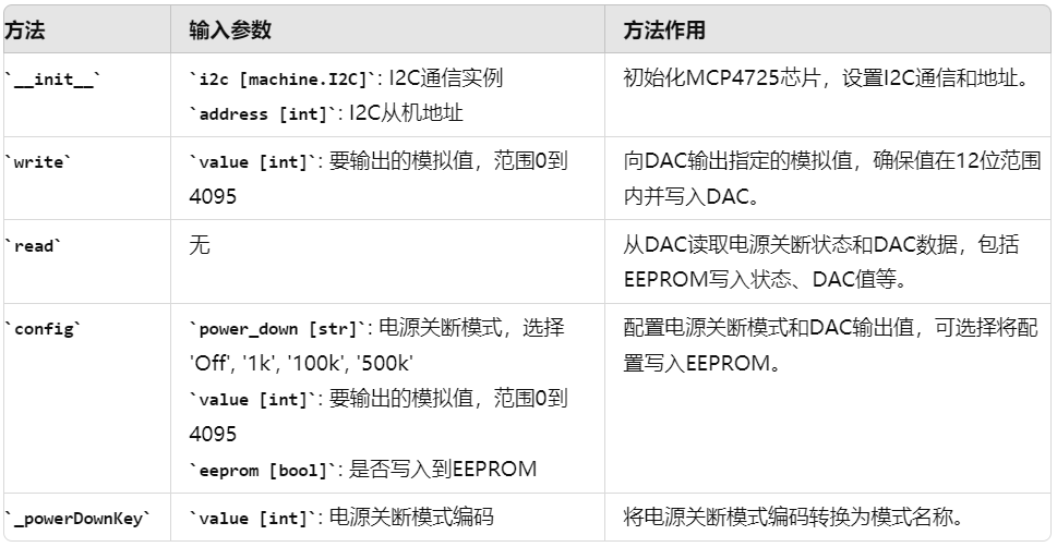
    Methods:
        __init__(i2c: machine.I2C, address: int = 0x60):
            Initialize MCP4725 instance and set I2C object and address.
        write(value: int) -> bool:
            Write analog value to MCP4725. Value range 0‑4095. Return write success status.
        read() -> tuple:
            Read status information from MCP4725 including power‑down mode and DAC output value.
        config(power_down: str = 'Off', value: int = 0, eeprom: bool = False) -> bool:
            Configure MCP4725 power‑down mode and output value. Optionally write settings into EEPROM.
        _powerDownKey(value: int) -> str:
            Convert power‑down mode numeric code back to mode name for config and read operations.
    """
    # Class variables
    # Define MCP4725 I2C addresses; typical choices are 0x60 or 0x61
    BUS_ADDRESS = [0x60, 0x61, 0x62, 0x63, 0x64, 0x65, 0x66, 0x67]
    # Define MCP4725 power‑down modes. Keys are mode names, values are mode codes.
    POWER_DOWN_MODE = {'Off': 0, '1k': 1, '100k': 2, '500k': 3}
    def __init__(self, i2c: I2C, address: int = 0x60) -> None:
        """
        Initialize MCP4725 chip.
        This method sets basic parameters for the MCP4725 DAC chip including I2C communication object and I2C address.
        Args:
            i2c (I2C): I2C object used for MCP4725 communication.
            address (int, optional): MCP4725 I2C address, default 0x62.
        Returns:
            None: This method returns nothing.
        Raises:
            ValueError: Raised if supplied address is not within valid I2C address list.
        """
        if address not in self.BUS_ADDRESS:
            raise ValueError(f"Invalid I2C address: {hex(address)}. Valid addresses are: {self.BUS_ADDRESS}")
        # Initialize I2C communication and address for MCP4725
        self.i2c = i2c
        self.address = address
        # Buffer for values written to DAC
        self._writeBuffer = bytearray(2)
    def write(self, value: int) -> bool:
        """
        Write analog value to MCP4725 DAC for output.
        Converts input analog value into chip‑recognizable format and sends it over I2C to MCP4725.
        Args:
            value (int): Analog value to output, range 0 to 4095.
        Returns:
            bool: Return True if write completes and 2 ACK acknowledgements are received; otherwise False.
        Raises:
            ValueError: Raised if input value falls outside 0‑4095 range.
        """
        if not (0 <= value <= 4095):
            raise ValueError("Value must be between 0 and 4095")
        # Constrain input value to 0‑4095 and ensure 12‑bit width
        value = value & 0xFFF
        # Store high 8 bits into first byte of buffer
        self._writeBuffer[0] = (value >> 8) & 0xFF
        # Store low 8 bits into second byte of buffer
        self._writeBuffer[1] = value & 0xFF
        # Write buffer content to DAC, return number of slave ACKs received
        return self.i2c.writeto(self.address, self._writeBuffer) == 2
    def read(self) -> tuple:
        '''
        Read power‑down bits and DAC data bits from MCP4725 chip.
        Reads 5‑byte data packet from MCP4725 and parses power‑down state, current DAC output value and EEPROM stored data.
        Returned fields:
        - eeprom_write_busy (boolean): True = EEPROM write not busy, False = busy
        - power_down (string): Current power‑down mode (e.g. "Normal operation" or "Power‑down")
        - value (integer): Current DAC output value, range 0‑4095
        - eeprom_power_down (string): Power‑down mode stored inside EEPROM
        - eeprom_value (integer): DAC output value stored inside EEPROM, range 0‑4095
        Returns:
            tuple: Tuple containing above fields when read succeeds; return None if read fails or data length is incorrect.
        Raises:
            None: This method raises no exceptions.
        '''
        # Create receive data buffer
        buf = bytearray(5)
        # Read 5‑byte data from MCP4725 into buffer
        self.i2c.readfrom_into(self.address, buf)
        # Check buffer length equals 5
        if len(buf) == 5:
            # Parse EEPROM write‑busy status
            eeprom_write_busy = (buf[0] & 0x80) == 0
            # Parse current power‑down mode
            power_down = self._powerDownKey((buf[0] >> 1) & 0x03)
            # Parse current output value
            value = ((buf[1] << 8) | (buf[2])) >> 4
            # Parse EEPROM‑stored power‑down mode
            eeprom_power_down = self._powerDownKey((buf[3] >> 5) & 0x03)
            # Parse EEPROM‑stored DAC output value
            eeprom_value = ((buf[3] & 0x0f) << 8) | buf[4]
            # Return tuple with all parsed fields
            return (eeprom_write_busy, power_down, value, eeprom_power_down, eeprom_value)
        return None
    def config(self, power_down: str = 'Off', value: int = 0, eeprom: bool = False) -> bool:
        """
        Configure MCP4725 chip power‑down mode and output value.
        Sets power‑down mode, voltage output value and optionally writes configuration into EEPROM.
        Args:
            power_down (str, optional): Power‑down mode, default 'Off'. Valid options refer to MCP4725.POWER_DOWN_MODE.
            value (int, optional): Analog output value, range 0‑4095, default 0.
            eeprom (bool, optional): Whether to save configuration to EEPROM, default False.
        Returns:
            bool: True for successful write, False otherwise.
        Raises:
            ValueError: Raised for invalid power‑down mode, out‑of‑range analog value or wrong type for eeprom parameter.
        """
        # Validate input power‑down mode
        if power_down not in MCP4725.POWER_DOWN_MODE.keys():
            raise ValueError("Invalid power down mode: {}".format(power_down))
        # Validate analog value within 0‑4095
        if not (0 <= value <= 4095):
            raise ValueError("Value must be between 0 and 4095")
        # Validate eeprom argument is boolean
        if not isinstance(eeprom, bool):
            raise ValueError("eeprom must be a boolean value")
        # Initialize configuration buffer
        buf = bytearray()
        # Build configuration byte including power‑down mode
        conf = 0x40 | (MCP4725.POWER_DOWN_MODE[power_down] << 1)
        if eeprom:
            # Set flag bit if EEPROM write is required
            conf = conf | 0x60
        buf.append(conf)
        # Ensure output value stays inside valid range
        value = value & 0xFFF
        # Append high 8 bits of output value
        buf.append(value >> 4)
        # Append low 4 bits of output value
        buf.append((value & 0x0F) << 4)
        # Send configuration buffer to MCP4725, return write status
        return self.i2c.writeto(self.address, buf) == 3
    def _powerDownKey(self, value: int) -> str:
        """
        Convert numeric power‑down‑mode code to corresponding mode name.
        Looks up mode name from given numeric power‑down‑mode code.
        Args:
            value (int): Numeric power‑down‑mode code.
        Returns:
            str: Matching power‑down‑mode name string.
        Raises:
            KeyError: Raised when no matching mode name exists for given code.
        """
        for key, item in MCP4725.POWER_DOWN_MODE.items():
            if item == value:
                return key
        raise KeyError("No matching power down mode for value: {}".format(value))
# ======================================== Initialization ==========================================
# ======================================== Main program ===========================================
Brief summary of implemented functions:
__init__() initialization method Constructor initializes MCP4725 I2C communication and address, creates write‑destination bytearray two‑byte contiguous memory buffer for packing data as byte stream for transmission.
write() DAC output‑value method Clamp input value to range 0‑4095. Separate high‑8‑bit and low‑8‑bit segments and store them inside _writeBuffer. Transmit buffer content to DAC over I2C bus.
read() DAC data‑read method Read five‑byte packet from DAC containing EEPROM write‑busy flag, current and EEPROM‑saved power‑down modes, current and EEPROM‑saved DAC output values. Return all data as a tuple.
config() DAC power‑down‑mode configuration method Generate configuration byte according to input power‑down mode and output value. Optionally enable EEPROM‑write flag. Send configuration to DAC via I2C bus.
_powerDownKey() internal helper method Convert numeric power‑down‑mode code to human‑readable mode name string.
Example workflow for generating required analog‑voltage output with MCP4725:
- Sine‑Wave Generation with MCP4725
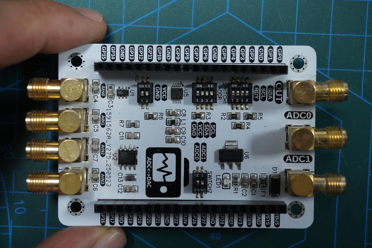
For this experiment insert the Elegance‑One Data‑Conversion Board onto the Elegance‑One Universal Compatible Expansion Board. Turn on the SCL, SDA and RDY switches of SWITCH1 DIP switch on the Data‑Conversion Board. Also enable the ADC1 switch option of SWITCH2.
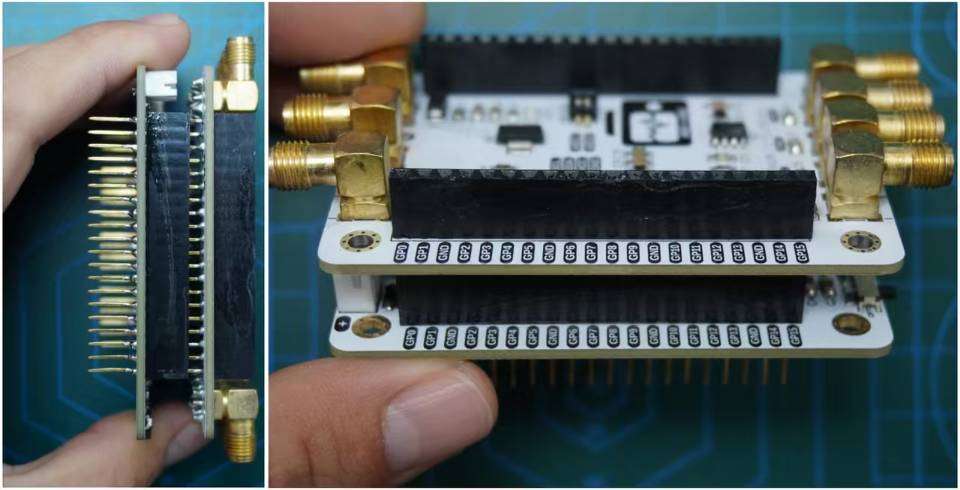
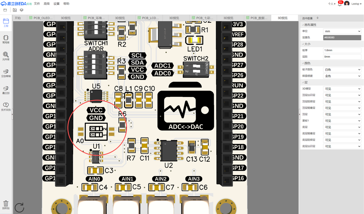
Set one address option using the A0 DIP‑switch for MCP4725. This example enables the GND position, so MCP4725 I²C address is 0x60.
Connect Mini‑USB cable to serial port on Elegance‑One Universal Compatible Expansion Board. GP0 and GP1 are default hardware UART0 pins for Raspberry Pi Pico.
Component wiring table:
The DAC analog‑output on Elegance‑One Data‑Conversion Board uses SMA connector. Use SMA‑to‑MCX adapter cable to connect DAC OUT output SMA port to internal ADC1 SMA input port on the same board.
Source code is located in resource package under elegance‑devkit v1\Demo\62 DAC_Sin.
The example below uses external MCP4725 DAC chip to generate sine‑wave signals. ADC reads back voltage values and voltages are transmitted over serial port.
# Python env   : MicroPython v1.23.0
# -*- coding: utf-8 -*-
# @Time    : 2024/9/1 2:10 PM
# @Author  : Li Qingshui
# @File    : main.py
# @Description : DAC experiment, generate sine waveform using external DAC chip
# ======================================== Import related modules ========================================
# Import hardware‑related modules
from machine import ADC, Timer, Pin, I2C, UART
# Import time‑related modules
import time
# Import MicroPython internal‑structure access module
import micropython
# Import math library for sine‑wave calculation
import math
# Import mcp4725 module for DAC chip control
from mcp4725 import MCP4725
# ======================================== Global variables ============================================
# MCP4725 chip address
DAC_ADDRESS = 0x00
# Voltage conversion coefficient
adc_conversion_factor = 3.3 / (65535)
# ======================================== Function definitions ============================================
# Timer callback function
def timer_callback(timer: Timer) -> None:
    """
    Timer callback for periodic ADC sampling and invoking user‑defined callback.
    Args:
        timer (machine.Timer): Timer instance.
    Returns:
        None
    """
    global adc,adc_conversion_factor
    # Read ADC sample
    value = adc.read_u16() * adc_conversion_factor
    # Schedule user‑defined callback
    micropython.schedule(user_callback, (value))

# User‑defined callback function
def user_callback(value: float) -> None:
    """
    User callback function for processing ADC‑sampled voltage and sending data over UART.
    Args:
        value (float): Voltage value acquired by ADC.
    Returns:
        None
    """
    global uart
    # Format float value to two decimal places
    formatted_value = "{:.2f}".format(value)
    # Send sampled voltage via serial port
    uart.write(str(formatted_value) + '\r\n')
    # Print sampled voltage on terminal
    print('dac generated voltage: ' + str(formatted_value))
# ======================================== Custom classes ============================================
# ======================================== Initialization ==========================================
# 3‑second delay for power‑on stabilization
time.sleep(3)
# Print debug information
print("FreakStudio : Using DAC to generate sine wave")
# Create hardware I2C instance: I2C1 peripheral, 400 kHz clock, SDA=Pin2, SCL=Pin3
i2c = I2C(id=1, sda=Pin(2), scl=Pin(3), freq=400000)
# Scan I2C‑bus attached slave devices and return address list
devices_list = i2c.scan()
print('START I2C SCANNER')
if len(devices_list) == 0:
    print("No i2c device !")
else:
    print('i2c devices found:', len(devices_list))
    for device in devices_list:
        # Detect DAC‑chip address range 0x60‑0x61
        if 0x60 <= device <= 0x61:
            print("I2C hexadecimal address: ", hex(device))
            DAC_ADDRESS = device
# Create DAC object using I2C peripheral and detected address
dac = MCP4725(i2c, DAC_ADDRESS)
# Read DAC configuration information
eeprom_write_busy, power_down, value, eeprom_power_down, eeprom_value = dac.read()
print(eeprom_write_busy, power_down, value, eeprom_power_down, eeprom_value)
# Configure DAC: disable power‑down mode, output 0 V, write settings into EEPROM
dac.config(power_down='Off',value=0,eeprom=True)
# 50 ms delay; immediate read after configuration causes errors
time.sleep_ms(50)
# Read DAC configuration information again
eeprom_write_busy, power_down, value, eeprom_power_down, eeprom_value = dac.read()
print(eeprom_write_busy, power_down, value, eeprom_power_down, eeprom_value)
# Create ADC instance: ADC1‑GP27
adc = ADC(1)
# Create software‑timer object
timer = Timer(-1)
# Start timer, trigger timer_callback every 5 ms for ADC voltage sampling
timer.init(period=5, mode=Timer.PERIODIC, callback=timer_callback)
# Create UART object with baudrate 115200
uart = UART(0, 115200)
# Configure UART: baudrate 115200, 8 data bits, no parity, 1 stop bit, tx=0, rx=1, timeout 100 ms
uart.init(baudrate  = 115200,
          bits      = 8,
          parity    = None,
          stop      = 1,
          tx        = 0,
          rx        = 1,
          timeout   = 100)
# ======================================== Main program ===========================================
# Generate sine wave
for i in range(10000):
    # Compute sine‑wave voltage
    value = 3.3 * math.sin(2 * math.pi * i / 100) + 3.3
    # Convert voltage value to integer DAC code
    value = int(value * 4095 / 6.6)
    # Write analog value to DAC
    dac.write(value)
    # 10 ms delay
    time.sleep_ms(10)
# Stop ADC sampling
timer.deinit()
Program workflow:
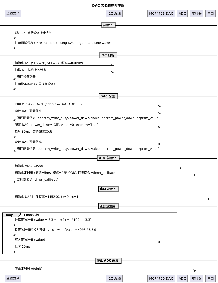
‑ 3‑second waiting period for board power‑on stabilization. ‑ Create I2C instance and scan I2C bus to detect DAC chip address. ‑ Instantiate and configure MCP4725 DAC object, read and apply DAC settings. ‑ Create ADC instance, configure periodic‑sampling timer and UART for data transmission. Inside timer callback read ADC samples and pass values into user_callback. User‑callback formats voltage to two decimal places and sends data over serial port.
Main‑loop operations:
- Generate sine‑wave samples and output them via DAC, controlling output frequency and amplitude.
- Stop timer after waveform generation completes to halt ADC sampling.
Overall timing‑sequence diagram:
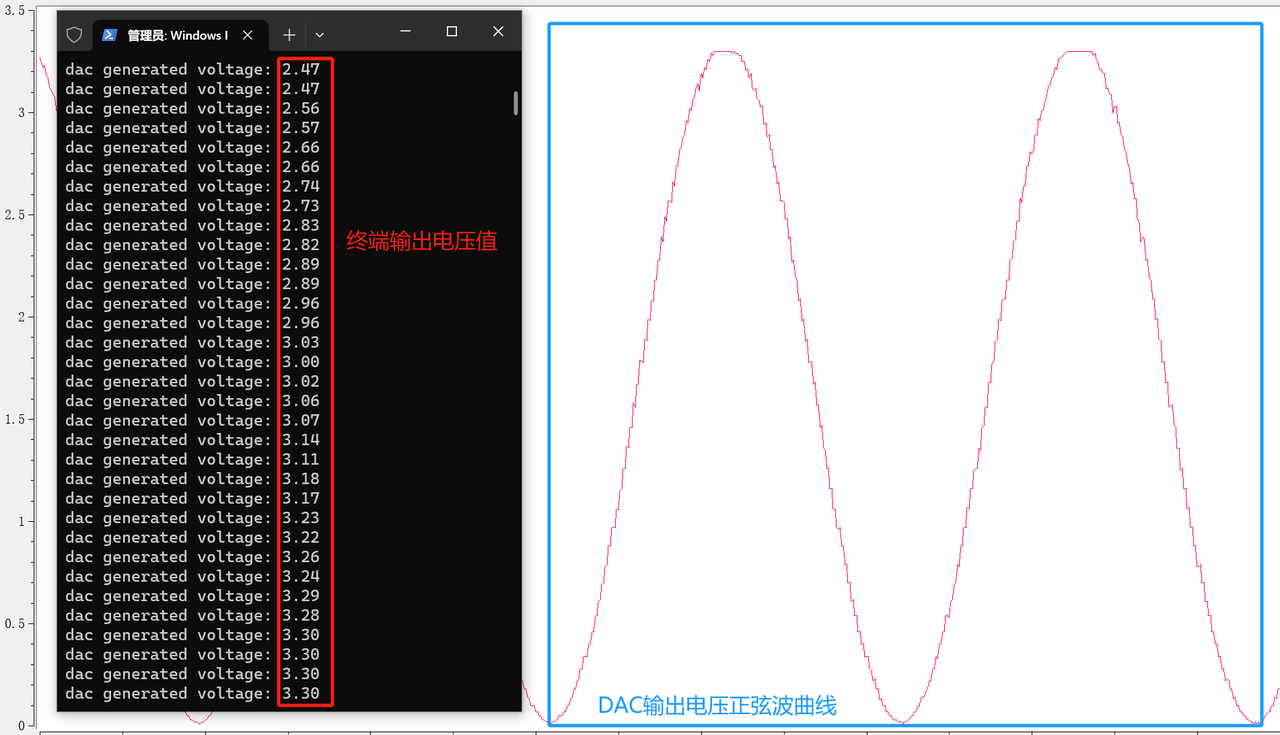
Launch SerialPlot software, select correct COM port for USB‑to‑TTL adapter and click Open.
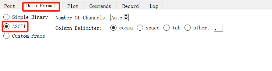
Select ASCII for data format; keep remaining parameters as defaults.

Flash firmware and open serial terminal. Output example:
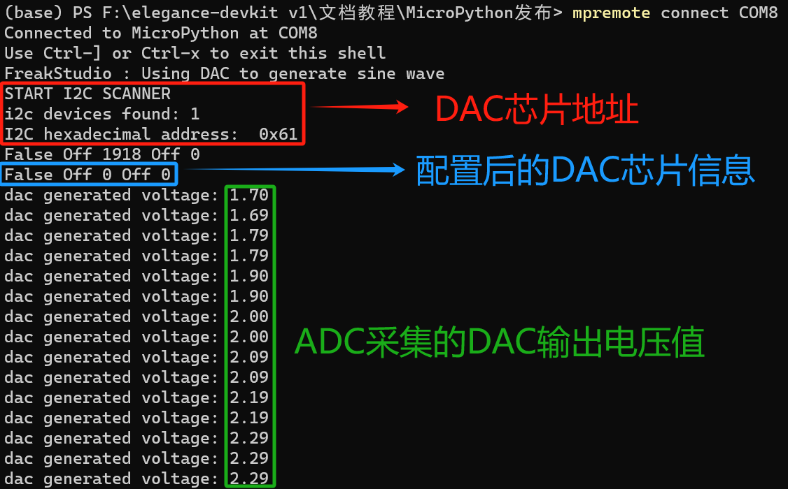
The MCP4725 DAC chip address is shown as 0x60. Driver class methods and chip configuration work correctly.
Inside SerialPlot you can observe the sine‑wave curve generated by DAC output voltage.