MicroPython + JY61 Gyro: Serial Driver, Custom Protocol & Data Visualization
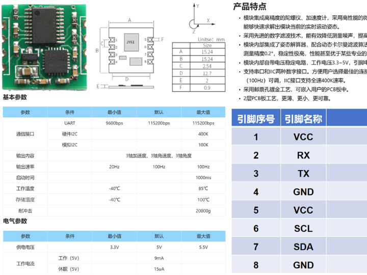
This article introduces the JY61 six-axis gyroscope, covering its UART data frame protocol, checksum calculation, data conversion and available control commands
COMPONENTS
PROJECT DESCRIPTION
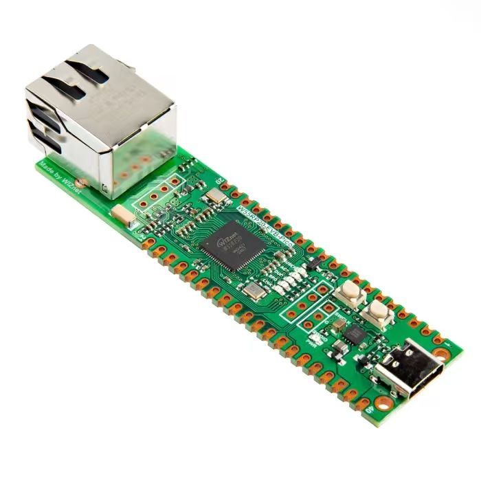
【Preliminary Note】The original hardware example in this article was written based on the RP2040. The actual hardware used in this hands-on demonstration features the W55RP20 as the main controller chip. The circuit logic and UF2 flashing operation principles are universally applicable, with only the main controller model differing. The original chip model mentioned in the circuit descriptions below is provided for reference purposes only.
Tweet: Parsing JY61 gyroscope protocol frames via serial port
1. Introduction to JY61 Six-Axis Gyroscope
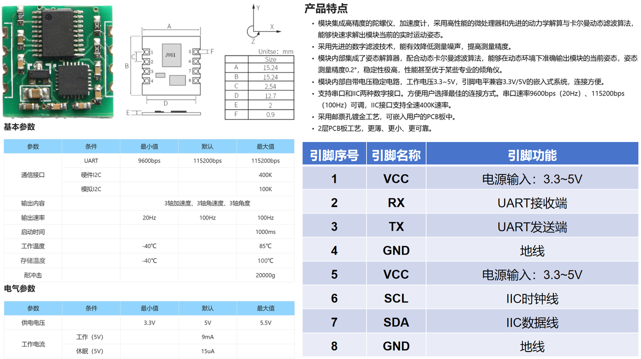
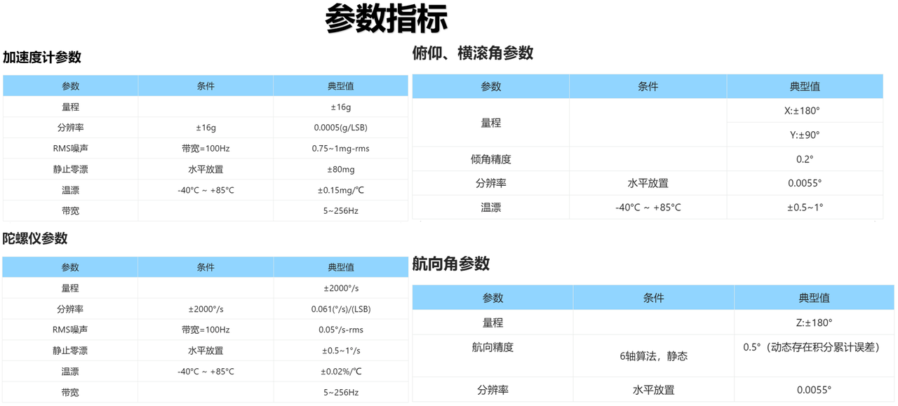
JY61 is a high-performance 3D motion attitude measurement system based on MEMS technology. It integrates a three-axis gyroscope and a three-axis accelerometer. Compared with the MPU6050 six-axis gyroscope module, JY61 performs quaternion calculation and Kalman filtering via its built-in microcontroller, supports communication in both UART and I2C modes, adopts a custom protocol frame during communication, and supports completing operations such as sensor angle zeroing, calibration and sleep by sending command packets through the serial port.
2. Introduction to JY61 Serial Port Protocol
2.1 Data Reading
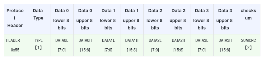
After power-on, the JY61 starts operating immediately and cyclically transmits 1 frame of data (which contains 11 data packets) via the serial port. The format of the data frame is as follows:
The parameters are defined as follows:
Frame Header HEADER - Value is 0x55, used for data synchronization
Data Type Type - indicates the data type, and there are three types in total: 0x51,0x52 and 0x53
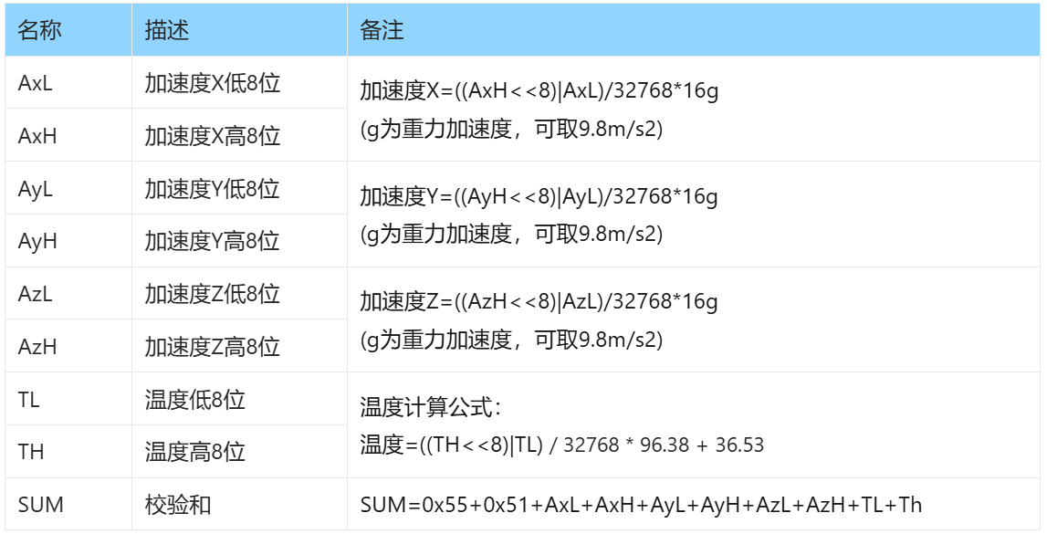
0x51- Indicates that acceleration data is sent
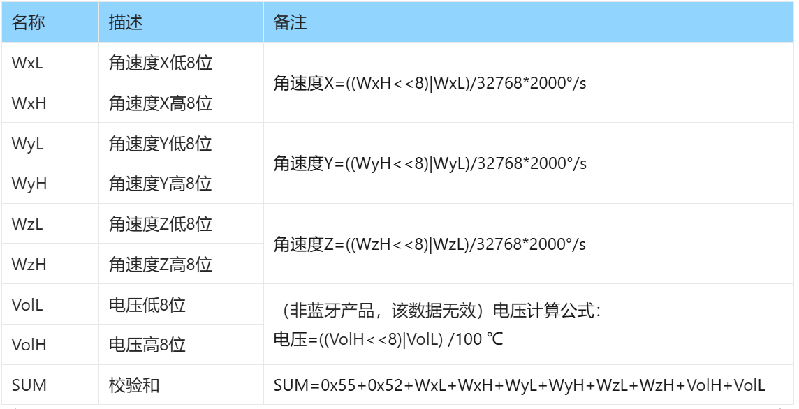
0x52 - indicates that angular velocity data is sent
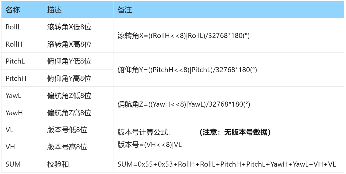
0x53 - indicates that angle data is to be transmitted
Data Bit DATA - transmitted in two parts: the upper 8 bits DATAxH and the lower 8 bits DATAxL, where x ranges from 0 to 3, and the meaning of each data bit varies depending on the data type Type
SUMCRC is of char type, taking the lower 8 bits of the checksum
Here, it should be noted that:
The data is transmitted in hexadecimal format
There are a total of 8 data bits: each piece of data is transmitted sequentially in the order of the low byte and the high byte, and the two are combined into a signed short-type data. For example, for the data DATA1, DATA1L is the low byte and DATA1H is the high byte. The conversion method is as follows: assuming DATA1 is the actual data, DATA1H is its high byte part and DATA1L is its low byte part, then:
DATA1=(short)((short)DATA1H<<8 | DATA1L)
It must be noted here that DATA1H must first be cast to a signed short type before performing bit shifting, and the data type of DATA1 is also a signed short, so that negative values can be represented correctly.
2.2 Command Transmission
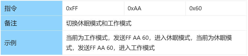
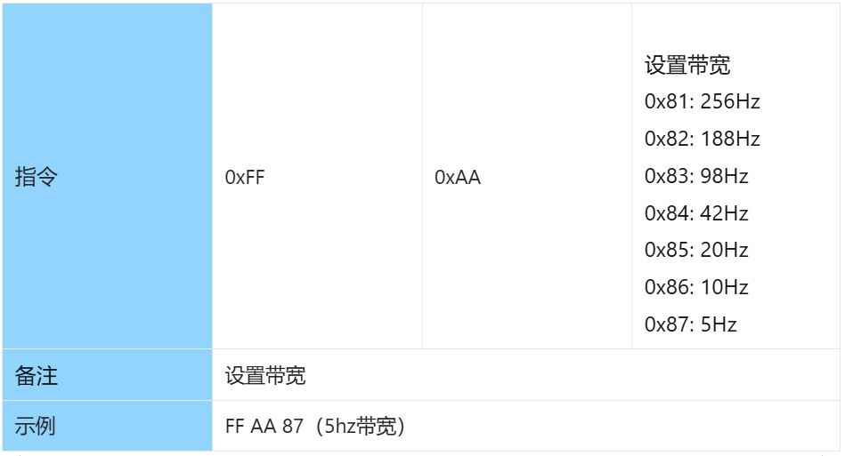
When sending commands, please follow the protocol below and note that the data shall be sent in hexadecimal format:
The following commands are available to be sent:
Z-axis angle zero reset
Note: The sensor must be kept stationary in a horizontal/vertical position during calibration and zeroing of the z-axis angle!
Accelerometer Calibration
Note: The sensor must be kept stationary in a horizontal/vertical position during calibration and zeroing of the z-axis angle!