



MicroPython ADS1115 Handbook: I2C, Driver, Trigger & Filter
ADS1115 MicroPython full handbook
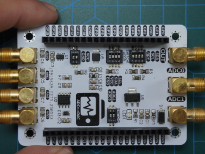
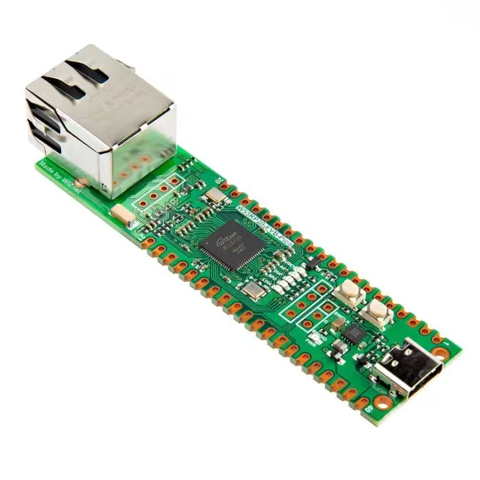
- Pre‑experiment Preparation
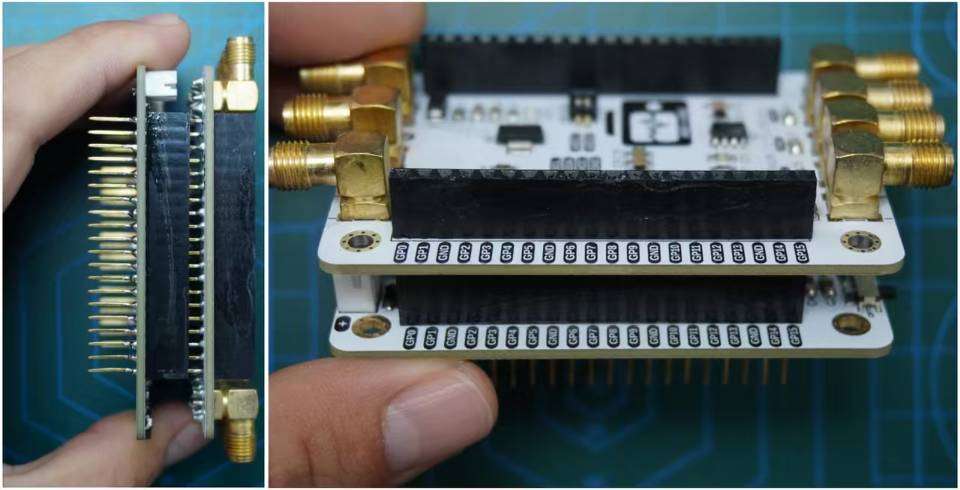
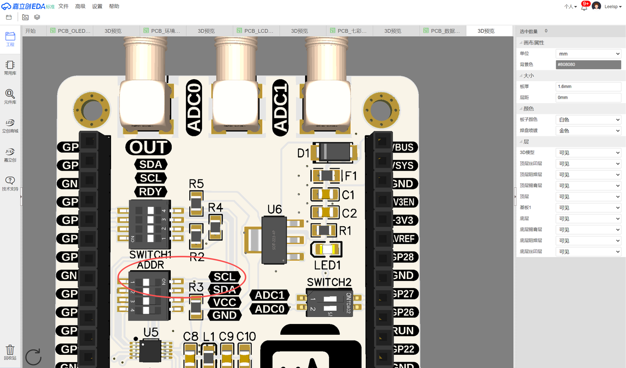
For this experiment, insert the Elegance‑One Data‑Conversion Expansion Board onto the Elegance‑One Universal Compatible Expansion Board. Turn on the SCL, SDA and RDY options of the SWITCH1 DIP switch on the Data‑Conversion Board.
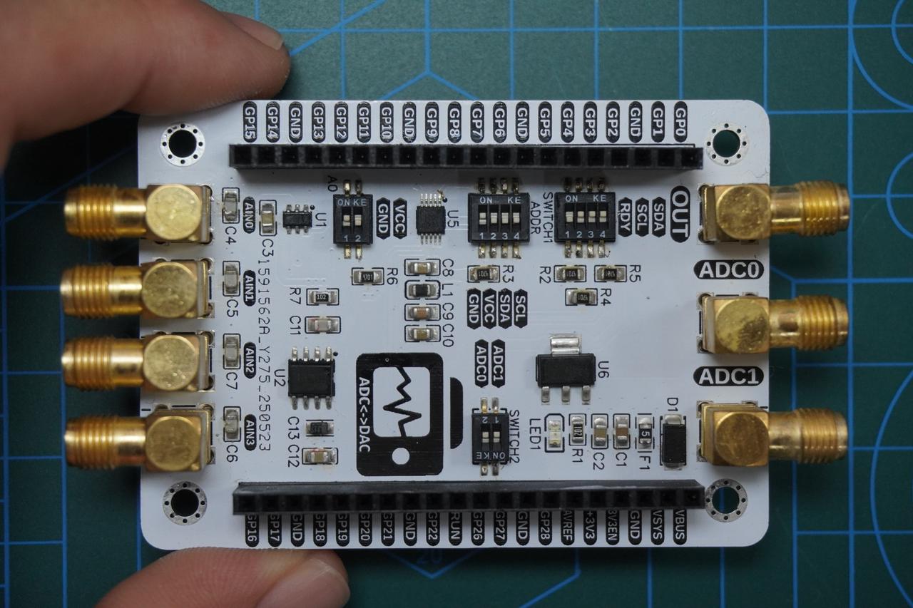
Additionally select one address via the ADDR DIP switch for the ADS1115 chip (only one switch position may be toggled). In this example the GND position is selected, so the I²C slave address of ADS1115 is 0x48.
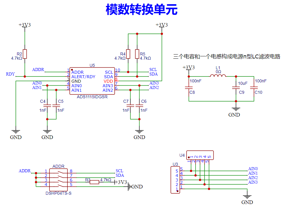
On the hardware design of the ADC module on the Elegance‑One Data‑Conversion Board, a 1 nF filter capacitor is added to each AIN input channel to suppress high‑frequency noise. A π‑type LC power‑supply filter circuit is implemented on the power rail to guarantee stable power.
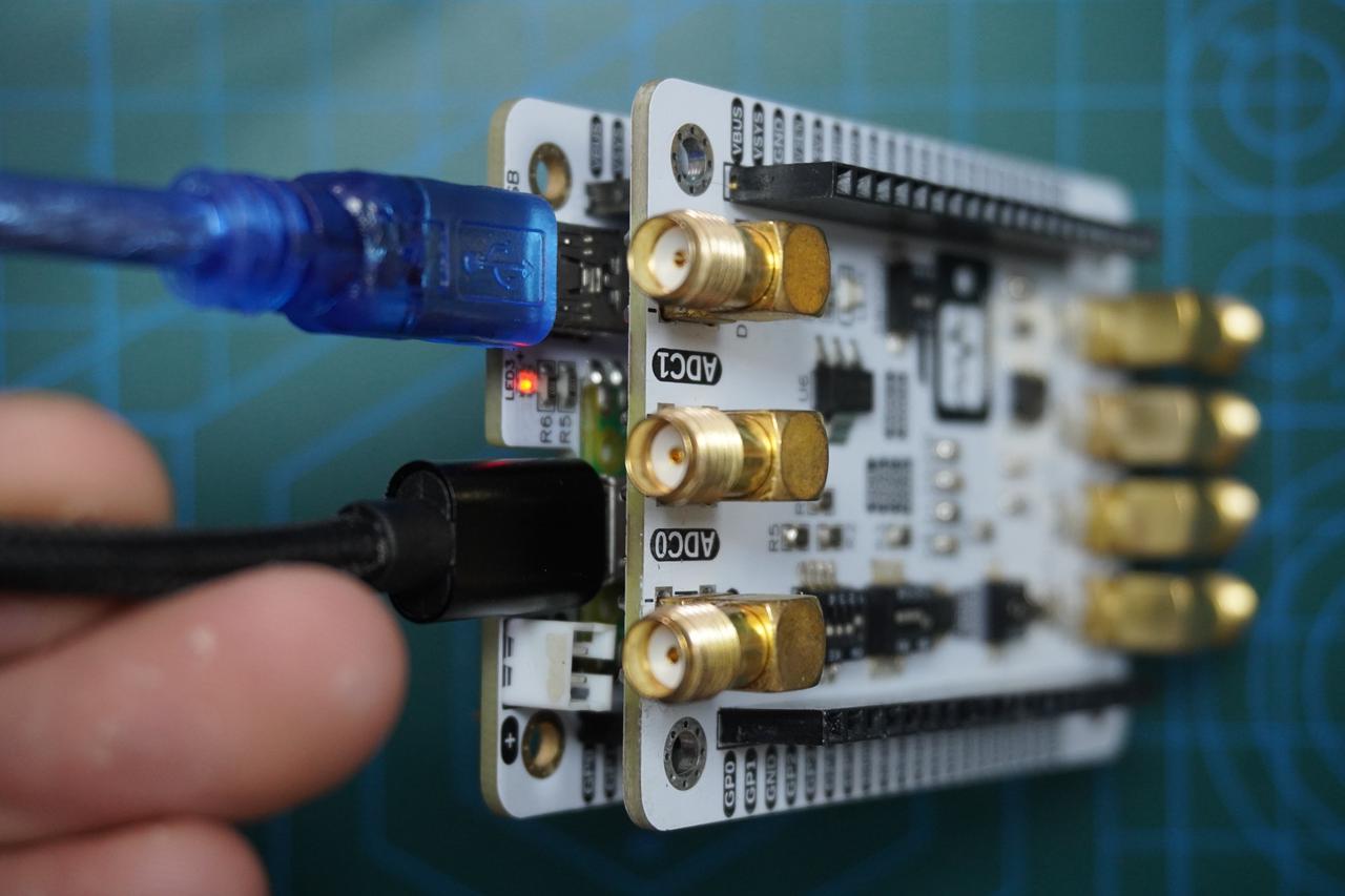
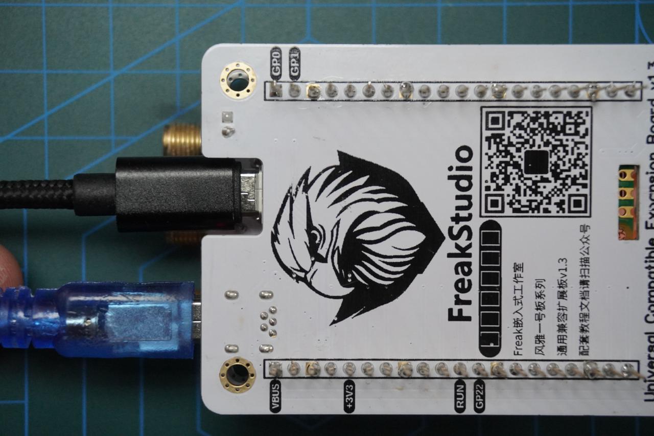
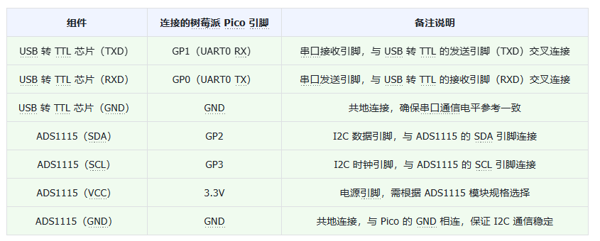
Furthermore connect a MiniUSB cable to the serial port on the Elegance‑One Universal Compatible Expansion Board. GP0 and GP1 are the default hardware UART0 pins of Raspberry Pi Pico.
Physical photos after assembly:
Wiring table:
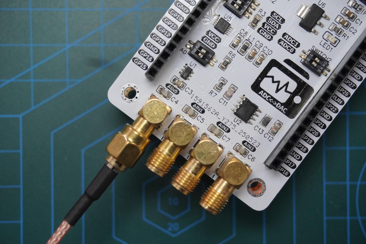
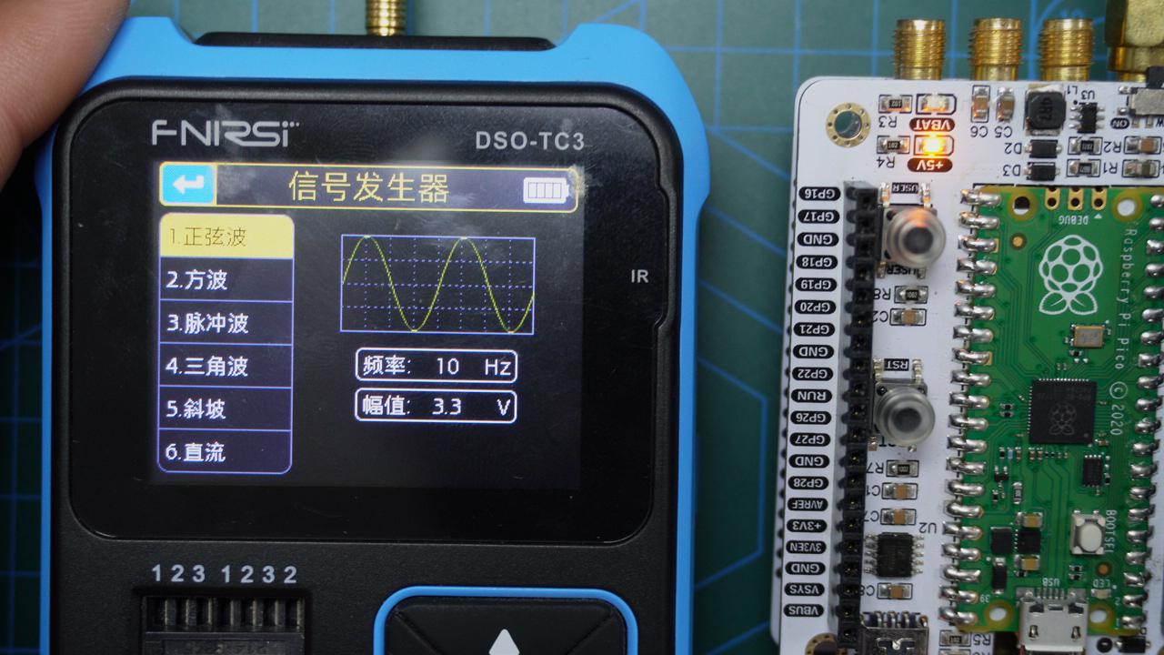
The signal input for the ADC unit on the Elegance‑One Data‑Conversion Board uses SMA connectors. Use SMA‑to‑MCX adapter cable to connect the AIN0 input of ADC unit to the DDS signal‑generator output port.
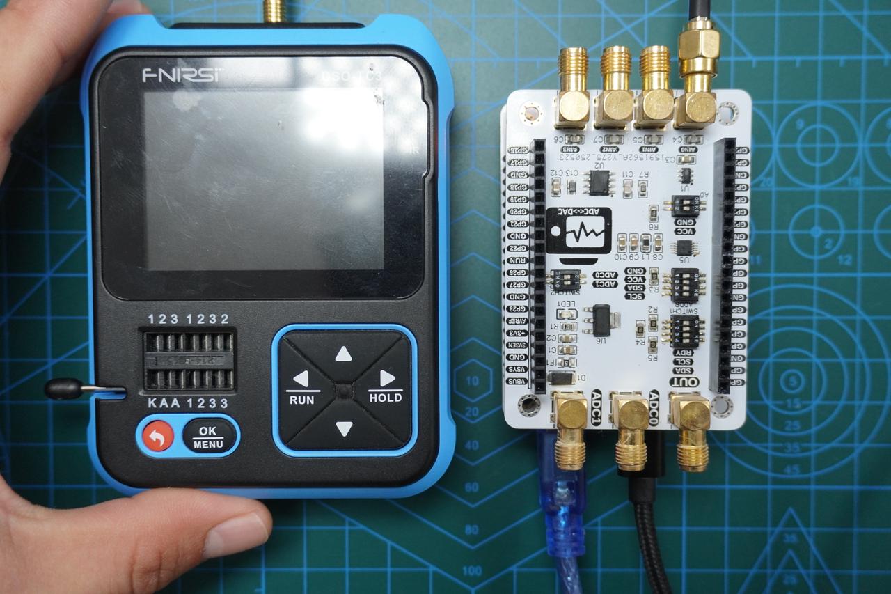
Complete physical connection diagram:
- Implementation of Custom ADS1115 Class
In the following code snippet a custom ADS1115 class is implemented for communication and control of the ADS1115 chip. The class interacts with ADS1115 over the I2C interface and provides functions for configuration, data reading and interrupt handling.
Sample code:
# Python env   : MicroPython v1.23.0
# -*- coding: utf-8 -*-
# @Time    : 2024/10/7 2:24 PM
# @Author  : Li Qingshui
# @File    : ads1115.py
# @Description : Driver class for external ADC chip ADS1115
# Reference code: https://github.com/robert-hh/ads1x15
# This code is developed by robert‑hh and released under MIT license.
# ======================================== Import related modules =========================================
# Import time‑related modules
import time
# Import MicroPython related modules
from micropython import const
import micropython
# Import hardware‑related modules
from machine import Pin, I2C
# ======================================== Global variables ============================================
# ======================================== Function definitions ============================================
# ======================================== Custom classes ============================================
# Custom ADS1115 class
class ADS1115:
    """
    ADS1115 class for controlling external ADS1115 ADC chip. Communicates with sensor via I2C interface, reads analog signals and converts them into digital values.
    Attributes:
        i2c (machine.I2C): I2C interface object used for ADS1115 communication.
        address (int): I2C address of ADS1115, default 0x48.
        gain_index (int): Index value for current gain setting.
        alert_pin (Pin, optional): Alert pin providing external interrupt notification. Default None.
        callback (Callable, optional): Callback function triggered on alert event. Default None.
    Class Variables:
        REGISTER_CONVERT (const): Conversion register address.
        REGISTER_CONFIG (const): Configuration register address.
        REGISTER_LOWTHRESH (const): Low‑threshold register address.
        REGISTER_HITHRESH (const): High‑threshold register address.
        OS_MASK (const): Operation status mask.
        OS_SINGLE (const): Start single‑shot conversion.
        OS_BUSY (const): Conversion in progress when reading.
        OS_NOTBUSY (const): Conversion completed when reading.
        MUX_MASK (const): Multiplexer mask.
        MUX_DIFF_0_1 (const): Differential input: AIN0 ‑ AIN1.
        MUX_DIFF_0_3 (const): Differential input: AIN0 ‑ AIN3.
        MUX_DIFF_1_3 (const): Differential input: AIN1 ‑ AIN3.
        MUX_DIFF_2_3 (const): Differential input: AIN2 ‑ AIN3.
        MUX_SINGLE_0 (const): Single‑ended input: AIN0.
        MUX_SINGLE_1 (const): Single‑ended input: AIN1.
        MUX_SINGLE_2 (const): Single‑ended input: AIN2.
        MUX_SINGLE_3 (const): Single‑ended input: AIN3.
        PGA_MASK (const): Programmable‑gain‑amplifier mask.
        PGA_6_144V (const): +/-6.144V range, gain 2/3.
        PGA_4_096V (const): +/-4.096V range, gain 1.
        PGA_2_048V (const): +/-2.048V range, gain 2.
        PGA_1_024V (const): +/-1.024V range, gain 4.
        PGA_0_512V (const): +/-0.512V range, gain 8.
        PGA_0_256V (const): +/-0.256V range, gain 16.
        MODE_MASK (const): Operating‑mode mask.
        MODE_CONTIN (const): Continuous conversion mode.
        MODE_SINGLE (const): Single‑shot conversion mode.
        DR_MASK (const): Data‑rate mask.
        DR_8SPS (const): 8 samples per second.
        DR_16SPS (const): 16 samples per second.
        DR_32SPS (const): 32 samples per second.
        DR_64SPS (const): 64 samples per second.
        DR_128SPS (const): 128 samples per second.
        DR_250SPS (const): 250 samples per second.
        DR_475SPS (const): 475 samples per second.
        DR_860SPS (const): 860 samples per second.
        CMODE_MASK (const): Comparator‑mode mask.
        CMODE_TRAD (const): Traditional comparator mode with hysteresis.
        CMODE_WINDOW (const): Window comparator mode.
        CPOL_MASK (const): Comparator polarity mask.
        CPOL_ACTVLOW (const): ALERT/RDY pin active‑low.
        CPOL_ACTVHI (const): ALERT/RDY pin active‑high.
        CLAT_MASK (const): Comparator‑latch mask.
        CLAT_NONLAT (const): Non‑latching comparator.
        CLAT_LATCH (const): Latching comparator.
        CQUE_MASK (const): Comparator queue mask.
        CQUE_1CONV (const): Trigger ALERT/RDY after one conversion.
        CQUE_2CONV (const): Trigger ALERT/RDY after two conversions.
        CQUE_4CONV (const): Trigger ALERT/RDY after four conversions.
        CQUE_NONE (const): Disable comparator, pull ALERT/RDY high.
        GAINS (tuple): Register values corresponding to gain settings.
        GAINS_V (tuple): Voltage ranges corresponding to gain settings.
        CHANNELS (dict): Multiplexer configurations mapped to channels.
        RATES (tuple): Register values corresponding to data‑rate settings.
    Methods:
        __init__(i2c: machine.I2C, address: int = 0x48, gain: int = 2, alert_pin: Optional[int] = None, callback: Optional[Callable] = None):
            Initialize ADS1115 instance, set I2C address, gain, alert pin and callback function. Validate input I2C address and gain are within valid ranges.
        _get_gain_register_value(gain: float) -> int:
            Return corresponding register configuration value given gain value. Maps gain value to device register setting.
        _irq_handler(pin: machine.Pin):
            Internal interrupt handler. Invoked when alert pin triggers; executes callback if callback is assigned.
        read(rate: int = 4, channel1: int = 0, channel2: Optional[int] = None) -> int:
            Read ADC conversion result from specified channel and return raw value. Perform one ADC conversion according to configured sample rate and channels.
        set_conv(rate: int = 4, channel1: int = 0, channel2: Optional[int] = None):
            Set conversion rate and input channels. Configure ADC sample rate and desired input channels.
        raw_to_v(raw: int) -> float:
            Convert raw ADC reading into voltage value. Convert raw sample into real voltage using device gain and full‑scale range.
        alert_start(rate: int = 4, channel1: int = 0, channel2: Optional[int] = None,
                    threshold_high: int = 0x4000, threshold_low: int = 0, latched: bool = False):
            Start alert mode and configure thresholds. Configure alert functionality, define high/low trigger thresholds and latching behaviour.
        alert_read() -> int:
            Read ADC result captured under alert condition. Return relevant ADC data by reading alert‑pin state.
    """
    # Register address constants
    REGISTER_CONVERT = const(0x00)       # Conversion register
    REGISTER_CONFIG = const(0x01)        # Configuration register
    REGISTER_LOWTHRESH = const(0x02)     # Low‑threshold register
    REGISTER_HITHRESH = const(0x03)      # High‑threshold register
    # Configuration register bit masks and constants
    OS_MASK = const(0x8000)              # Operation status mask
    OS_SINGLE = const(0x8000)            # Write: start single‑shot conversion
    OS_BUSY = const(0x0000)              # Read: conversion in progress
    OS_NOTBUSY = const(0x8000)           # Read: conversion complete
    MUX_MASK = const(0x7000)             # Multiplexer mask
    MUX_DIFF_0_1 = const(0x0000)         # Differential input: AIN0 ‑ AIN1 (default)
    MUX_DIFF_0_3 = const(0x1000)         # Differential input: AIN0 ‑ AIN3
    MUX_DIFF_1_3 = const(0x2000)         # Differential input: AIN1 ‑ AIN3
    MUX_DIFF_2_3 = const(0x3000)         # Differential input: AIN2 ‑ AIN3
    MUX_SINGLE_0 = const(0x4000)         # Single‑ended input: AIN0
    MUX_SINGLE_1 = const(0x5000)         # Single‑ended input: AIN1
    MUX_SINGLE_2 = const(0x6000)         # Single‑ended input: AIN2
    MUX_SINGLE_3 = const(0x7000)         # Single‑ended input: AIN3
    PGA_MASK = const(0x0E00)             # Programmable gain amplifier mask
    PGA_6_144V = const(0x0000)           # +/-6.144V range, gain 2/3
    PGA_4_096V = const(0x0200)           # +/-4.096V range, gain 1
    PGA_2_048V = const(0x0400)           # +/-2.048V range, gain 2 (default)
    PGA_1_024V = const(0x0600)           # +/-1.024V range, gain 4
    PGA_0_512V = const(0x0800)           # +/-0.512V range, gain 8
    PGA_0_256V = const(0x0A00)           # +/-0.256V range, gain 16
    MODE_MASK = const(0x0100)            # Operating‑mode mask
    MODE_CONTIN = const(0x0000)          # Continuous conversion mode
    MODE_SINGLE = const(0x0100)          # Single‑shot conversion mode (default)
    DR_MASK = const(0x00E0)              # Data‑rate mask
    DR_8SPS = const(0x0000)              # 8 samples per second
    DR_16SPS = const(0x0020)             # 16 samples per second
    DR_32SPS = const(0x0040)             # 32 samples per second
    DR_64SPS = const(0x0060)             # 64 samples per second
    DR_128SPS = const(0x0080)            # 128 samples per second (default)
    DR_250SPS = const(0x00A0)            # 250 samples per second
    DR_475SPS = const(0x00C0)            # 475 samples per second
    DR_860SPS = const(0x00E0)            # 860 samples per second
    CMODE_MASK = const(0x0010)           # Comparator‑mode mask
    CMODE_TRAD = const(0x0000)           # Traditional comparator mode with hysteresis (default)
    CMODE_WINDOW = const(0x0010)         # Window comparator mode
    CPOL_MASK = const(0x0008)            # Comparator polarity mask
    CPOL_ACTVLOW = const(0x0000)         # ALERT/RDY pin active‑low (default)
    CPOL_ACTVHI = const(0x0008)          # ALERT/RDY pin active‑high
    CLAT_MASK = const(0x0004)            # Comparator‑latch mask
    CLAT_NONLAT = const(0x0000)          # Non‑latching comparator (default)
    CLAT_LATCH = const(0x0004)           # Latching comparator
    CQUE_MASK = const(0x0003)            # Comparator queue mask
    CQUE_1CONV = const(0x0000)           # Trigger ALERT/RDY after one conversion
    CQUE_2CONV = const(0x0001)           # Trigger ALERT/RDY after two conversions
    CQUE_4CONV = const(0x0002)           # Trigger ALERT/RDY after four conversions
    CQUE_NONE = const(0x0003)            # Disable comparator, pull ALERT/RDY high (default)
    # Register values for gain settings
    GAINS = (
        PGA_6_144V,  # 2/3x
        PGA_4_096V,  # 1x
        PGA_2_048V,  # 2x
        PGA_1_024V,  # 4x
        PGA_0_512V,  # 8x
        PGA_0_256V   # 16x
    )
    # Voltage ranges for corresponding gain settings
    GAINS_V = (
        6.144,  # 2/3x
        4.096,  # 1x
        2.048,  # 2x
        1.024,  # 4x
        0.512,  # 8x
        0.256   # 16x
    )
    # Multiplexer configurations mapped to channel combinations
    CHANNELS = {
        (0, None): MUX_SINGLE_0,
        (1, None): MUX_SINGLE_1,
        (2, None): MUX_SINGLE_2,
        (3, None): MUX_SINGLE_3,
        (0, 1): MUX_DIFF_0_1,
        (0, 3): MUX_DIFF_0_3,
        (1, 3): MUX_DIFF_1_3,
        (2, 3): MUX_DIFF_2_3,
    }
    # Register values for data‑rate settings
    RATES = (
        DR_8SPS,     # 8 samples per second
        DR_16SPS,    # 16 samples per second
        DR_32SPS,    # 32 samples per second
        DR_64SPS,    # 64 samples per second
        DR_128SPS ,  # 128 samples per second (default)
        DR_250SPS,   # 250 samples per second
        DR_475SPS,   # 475 samples per second
        DR_860SPS    # 860 samples per second
    )
    def __init__(self, i2c: I2C, address: int = 0x48, gain: int = 2, alert_pin: int =None, callback: callable = None) -> None:
        """
        Initialize ADS1115 instance.
        This method sets basic parameters for ADS1115 module including I2C address, gain value, alert pin and alert callback function.
        Args:
            i2c (machine.I2C): I2C object for ADS1115 communication.
            address (int, optional): ADS1115 I2C address, default 0x48.
            gain (int, optional): Gain setting determining input‑voltage range, default value 2 corresponding to +/-2.048V.
            alert_pin (int, optional): Alert pin number for receiving alert signals. Default None.
            callback (callable, optional): Callback function invoked when alert pin triggers. Default None.
        Returns:
            None: This method returns nothing.
        Raises:
            ValueError: Raised if gain or I2C address falls outside valid range.
        """
        # Validate ADS1115 I2C address: must be 0x48,0x49,0x4A or 0x4B
        if not 0x48 <= address <= 0x4B:
            raise ValueError("Invalid I2C address: 0x{:02X}".format(address))
        # Validate gain: allowed values are 2/3, 1, 2, 4, 8, 16
        if gain not in (2/3, 1, 2, 4, 8, 16):
            raise ValueError("Invalid gain: {}".format(gain))
        # Store I2C object
        self.i2c = i2c
        # Store device address
        self.address = address
        # Store index of selected gain setting
        try:
            self.gain_index = ADS1115.GAINS.index(self._get_gain_register_value(gain))
        except ValueError:
            raise ValueError("Gain setting not found in GAINS tuple.")
        # Temporary bytearray for read‑write operations
        self.temp2 = bytearray(2)
        # If alert pin is assigned
        if alert_pin is not None:
            # Configure ALERT pin as input
            self.alert_pin = Pin(alert_pin, Pin.IN)
            # Store user‑supplied callback
            self.callback = callback
            # Default trigger edge: falling edge
            self.alert_trigger = Pin.IRQ_FALLING
            # Attach interrupt handler
            self.alert_pin.irq(handler=lambda p: self._irq_handler(p), trigger=self.alert_trigger)
    def _get_gain_register_value(self, gain: float) -> int:
        """
        Return corresponding register configuration value for given gain.
        Maps gain magnitude to corresponding ADS1115 register setting.
        Args:
            gain (float): Gain value, allowed: 2/3, 1, 2, 4, 8, 16.
        Returns:
            int: Corresponding register configuration value.
        Raises:
            KeyError: Raised if gain is not present inside predefined gain mapping.
        """
        gain_map = {
            2/3: ADS1115.GAINS[0],
            1:   ADS1115.GAINS[1],
            2:   ADS1115.GAINS[2],
            4:   ADS1115.GAINS[3],
            8:   ADS1115.GAINS[4],
            16:  ADS1115.GAINS[5]
        }
        return gain_map[gain]
    def _irq_handler(self, pin: Pin) -> None:
        """
        Internal interrupt handler, schedules user callback via micropython.schedule.
        When interrupt fires, invoke user‑defined callback (if assigned) scheduled through micropython.schedule.
        Args:
            pin (machine.Pin): Pin object that triggered interrupt.
        Returns:
            None: This method returns nothing.
        """
        if hasattr(self, 'callback') and self.callback:
            micropython.schedule(self.callback, pin)
    def _write_register(self, register: int, value: int) -> None:
        """
        Write value into target register.
        Writes specified 16‑bit value to given register address.
        Args:
            register (int): Register address.
            value (int): Value to write.
        Returns:
            None: This method returns nothing.
        """
        # Extract high byte of value
        self.temp2[0] = (value >> 8) & 0xFF
        # Extract low byte of value
        self.temp2[1] = value & 0xFF
        # Perform register write
        self.i2c.writeto_mem(self.address, register, self.temp2)
    def _read_register(self, register: int) -> int:
        """
        Read value from register.
        Reads data from specified register and returns combined integer result.
        Args:
            register (int): Register address.
        Returns:
            int: Value read from register.
        """
        # Read register content into bytearray
        self.i2c.readfrom_mem_into(self.address, register, self.temp2)
        # Merge high and low byte and return integer value
        return (self.temp2[0] << 8) | self.temp2[1]
    def raw_to_v(self, raw: int) -> float:
        """
        Convert raw ADC sample to voltage.
        Transforms raw ADC reading into real‑world voltage according to current gain setting.
        Args:
            raw (int): Raw ADC integer reading.
        Returns:
            float: Converted voltage value.
        """
        # Calculate voltage per LSB
        v_p_b = ADS1115.GAINS_V[self.gain_index] / 32768
        # Return converted voltage
        return raw * v_p_b
    def set_conv(self, rate: int = 4, channel1: int = 0, channel2: int = None) -> None:
        """
        Set conversion rate and input channels.
        Configures ADC sampling rate and selects target input channels. Builds configuration value for hardware.
        Args:
            rate (int, optional): Data‑rate index, default 4 corresponding to 128 SPS.
            channel1 (int, optional): Main channel index, default 0.
            channel2 (int, optional): Differential‑pair secondary channel index, default None.
        Returns:
            None: This method returns nothing.
        Raises:
            ValueError: Raised if rate or channel index is invalid.
        """
        # Validate sampling‑rate index
        if rate not in range(len(ADS1115.RATES)):
            raise ValueError("Invalid rate: {}".format(rate))
        # Validate channel numbers
        if channel1 not in range(4) or (channel2 is not None and channel2 not in range(4)):
            raise ValueError("Invalid channel: {}".format(channel1))
        # Build configuration‑register value
        self.mode = (ADS1115.CQUE_NONE      | ADS1115.CLAT_NONLAT |
                     ADS1115.CPOL_ACTVLOW   | ADS1115.CMODE_TRAD |
                     ADS1115.RATES[rate]    | ADS1115.MODE_SINGLE |
                     ADS1115.OS_SINGLE      | ADS1115.GAINS[self.gain_index] |
                     ADS1115.CHANNELS.get((channel1, channel2), ADS1115.MUX_SINGLE_0))
    def read(self, rate: int = 4, channel1: int = 0, channel2: int = None) -> int:
        """
        Read ADC value from specified channel.
        Performs one‑shot ADC conversion with given rate and channel settings and returns raw signed integer result.
        Args:
            rate (int, optional): Data‑rate index, default 4 corresponding to 128 SPS.
            channel1 (int, optional): Main channel index, default 0.
            channel2 (int, optional): Differential‑pair secondary channel index, default None.
        Returns:
            int: Signed raw ADC reading. Negative values are properly sign‑extended.
        Raises:
            ValueError: Raised if rate or channel index is invalid.
        """
        # Validate sampling‑rate index
        if rate not in range(len(ADS1115.RATES)):
            raise ValueError("Invalid rate: {}".format(rate))
        # Validate channel numbers
        if channel1 not in range(4) or (channel2 is not None and channel2 not in range(4)):
            raise ValueError("Invalid channel: {}".format(channel1))
        # Write configuration register and start conversion
        self._write_register(
            ADS1115.REGISTER_CONFIG,
            (ADS1115.CQUE_NONE      | ADS1115.CLAT_NONLAT |
             ADS1115.CPOL_ACTVLOW   | ADS1115.CMODE_TRAD |
             ADS1115.RATES[rate]    | ADS1115.MODE_SINGLE |
             ADS1115.OS_SINGLE      | ADS1115.GAINS[self.gain_index] |
             ADS1115.CHANNELS.get((channel1, channel2), ADS1115.MUX_SINGLE_0))
        )
        # Block until conversion completes
        while not (self._read_register(ADS1115.REGISTER_CONFIG) & ADS1115.OS_NOTBUSY):
            time.sleep_ms(1)
        # Fetch conversion result
        res = self._read_register(ADS1115.REGISTER_CONVERT)
        # Return signed result
        return res if res < 32768 else res - 65536
    def read_rev(self) -> int:
        """
        Read conversion result and immediately trigger next conversion.
        Reads latest conversion result and uses stored self.mode setting to start subsequent conversion.
        Returns:
            int: Signed raw ADC reading. Negative values are properly sign‑extended.
        """
        # Read conversion register
        res = self._read_register(ADS1115.REGISTER_CONVERT)
        # Trigger next conversion using stored configuration
        self._write_register(ADS1115.REGISTER_CONFIG, self.mode)
        # Return signed result
        return res if res < 32768 else res - 65536
    def alert_start(self, rate: int = 4, channel1: int = 0, channel2: int = None,
                    threshold_high: int = 0x4000, threshold_low: int = 0, latched: bool = False) -> None:
        """
        Start continuous measurement with alert‑threshold configuration.
        Enables alert‑comparator functionality and configures high/low threshold values and latching behaviour.
        Args:
            rate (int, optional): Data‑rate index, default 4.
            channel1 (int, optional): Main channel index, default 0.
            channel2 (int, optional): Differential‑pair secondary channel index, default None.
            threshold_high (int, optional): Upper alert threshold, default 0x4000.
            threshold_low (int, optional): Lower alert threshold, default 0.
            latched (bool, optional): Enable comparator latching, default False.
        Returns:
            None: This method returns nothing.
        Raises:
            ValueError: Raised for invalid rate, channel or threshold settings.
        """
        # Validate sampling‑rate index
        if rate not in range(len(ADS1115.RATES)):
            raise ValueError("Invalid rate: {}".format(rate))
        # Validate channel numbers
        if channel1 not in range(4) or (channel2 is not None and channel2 not in range(4)):
            raise ValueError("Invalid channel: {}".format(channel1))
        # Validate threshold relation
        if threshold_high < threshold_low:
            raise ValueError("Invalid threshold: {} > {}".format(threshold_high, threshold_low))
        # Write low‑threshold register
        self._write_register(ADS1115.REGISTER_LOWTHRESH, threshold_low)
        # Write high‑threshold register
        self._write_register(ADS1115.REGISTER_HITHRESH, threshold_high)
        # Configure comparator and alert‑pin behaviour
        self._write_register(
            ADS1115.REGISTER_CONFIG,
            (ADS1115.CQUE_1CONV |
             (ADS1115.CLAT_LATCH if latched else ADS1115.CLAT_NONLAT) |
             ADS1115.CPOL_ACTVLOW | ADS1115.CMODE_TRAD |
             ADS1115.RATES[rate] | ADS1115.MODE_CONTIN |
             ADS1115.GAINS[self.gain_index] |
             ADS1115.CHANNELS.get((channel1, channel2), ADS1115.MUX_SINGLE_0))
        )
    def conversion_start(self, rate: int = 4, channel1: int = 0, channel2: int = None) -> None:
        """
        Start continuous conversions driven by ALERT/RDY ready signal.
        Enables continuous conversion mode using RDY‑ready indication on ALERT/RDY pin.
        Args:
            rate (int, optional): Data‑rate index, default 4.
            channel1 (int, optional): Main channel index, default 0.
            channel2 (int, optional): Differential‑pair secondary channel index, default None.
        Returns:
            None: This method returns nothing.
        Raises:
            ValueError: Raised for invalid rate or channel settings.
        """
        # Validate sampling‑rate index
        if rate not in range(len(ADS1115.RATES)):
            raise ValueError("Invalid rate: {}".format(rate))
        # Validate channel numbers
        if channel1 not in range(4) or (channel2 is not None and channel2 not in range(4)):
            raise ValueError("Invalid channel: {}".format(channel1))
        # Set low threshold to zero
        self._write_register(ADS1115.REGISTER_LOWTHRESH, 0)
        # Set high threshold to 0x8000 for RDY mode
        self._write_register(ADS1115.REGISTER_HITHRESH, 0x8000)
        # Configure register and start continuous conversion
        self._write_register(
            ADS1115.REGISTER_CONFIG,
            (ADS1115.CQUE_1CONV | ADS1115.CLAT_NONLAT |
             ADS1115.CPOL_ACTVLOW | ADS1115.CMODE_TRAD |
             ADS1115.RATES[rate] | ADS1115.MODE_CONTIN |
             ADS1115.GAINS[self.gain_index] |
             ADS1115.CHANNELS.get((channel1, channel2), ADS1115.MUX_SINGLE_0))
        )
    def alert_read(self) -> int:
        """
        Fetch latest conversion result under alert‑driven continuous‑measurement mode.
        Reads conversion register and performs sign correction for negative values.
        Returns:
            int: Signed raw ADC reading, range ‑32768 ~ 32767.
        """
        res = self._read_register(ADS1115.REGISTER_CONVERT)
        return res if res < 32768 else res - 65536
# ======================================== Initialization ==========================================
# ======================================== Main program ============================================
A set of constants are defined for ADS1115 register addresses, configuration bit masks and configuration values:
‑ Register‑address constants: define pointer‑register target addresses for conversion register, configuration register and threshold registers. ‑ Configuration‑register bit‑mask constants: these constants configure operating mode, gain, data rate and other parameters of ADS1115. ‑ Gain settings and corresponding voltage ranges: GAINS tuple stores register values for each gain; GAINS_V tuple stores corresponding full‑scale voltage range. ‑ Multiplexer configuration: CHANNELS dictionary maps channel combinations to mux setting bits for single‑ended or differential‑input selection. ‑ Data‑rate settings: RATES tuple holds register‑configuration values for all supported sampling rates.
These class‑level constants represent individual bits or bit‑fields inside configuration register. Bitwise‑OR (|) operations combine multiple settings into the final 16‑bit value written to ADS1115 configuration register.
Parameters passed into __init__ constructor:
‑ i2c: machine.I2C object for I2C communication with ADS1115. ‑ address: I2C slave address for ADS1115, default 0x48, valid range 0x48 to 0x4B. ‑ gain: gain setting, default 2 for ±2.048 V full‑scale; allowed values: 2/3, 1, 2, 4, 8, 16. ‑ alert_pin: optional alert‑interrupt pin number. ‑ callback: optional user callback invoked on alert‑pin assertion.
Address and gain validation is performed first. The I2C object and device address are stored as instance attributes. The corresponding register value for given gain is resolved and its index inside GAINS list is saved. A temporary bytearray object is allocated for subsequent read‑write operations. If an alert pin is supplied, that pin is configured as digital input and interrupt handler is attached. Inside _irq_handler, existence of callback function is checked and user callback is scheduled via micropython.schedule.
Major methods of ADS1115 class:
‑ _write_register: writes 16‑bit value into specified register. Splits 16‑bit value into high‑byte and low‑byte, uses I2C writeto_mem for register write. ‑ _read_register: reads 16‑bit value from target register. Uses readfrom_mem_into to fill temp bytearray, then merges bytes into integer return value. ‑ raw_to_v: converts raw ADC integer reading into real‑world voltage. Computes LSB voltage magnitude according to current gain index and multiplies by raw sample value. ‑ set_conv: configures ADC sampling rate and input channels. Validates rate‑index and channel‑index inputs. Builds combined configuration value and stores into self.mode attribute for later reuse. Usually used together with read_rev. ‑ read: performs single‑shot read from specified channel. Validates inputs, builds and writes configuration register value to start conversion. Loops polling OS_NOTBUSY bit until conversion finishes, returns sign‑corrected raw ADC result. ‑ read_rev: reads latest conversion result and immediately triggers next conversion using previously‑saved self.mode configuration. Returns sign‑corrected sample. Designed for timer‑driven periodic sampling together with set_conv. ‑ alert_start: enables continuous‑measurement alert mode and sets high/low threshold values. Suitable for threshold‑based interrupt triggering. Validates rate‑index, channel‑index and threshold‑value ordering. Writes threshold registers and builds configuration register for comparator‑alert operation. ‑ conversion_start: starts continuous‑conversion mode using ALERT/RDY ready‑signal indication. Validates inputs, sets low‑threshold register to 0 and high‑threshold register to 0x8000 to enable RDY‑ready‑status mode, writes configuration register to launch continuous conversions. ‑ alert_read: fetches latest conversion result under alert‑driven continuous‑measurement mode, performs sign correction for negative values.
Two main conversion workflows are supported:
‑ Single‑shot conversion mode: calling read writes configuration register to trigger one conversion, blocks waiting for completion and returns sample result. ‑ Continuous‑measurement mode: calling conversion_start or alert_start enables continuous conversions, optionally with threshold‑comparator and interrupt handling.
- Interrupt‑triggered mode: uses ADS1115 ALERT/RDY hardware‑interrupt pin to notify MCU on conversion completion, suited for event‑driven real‑time response.
- Timer‑triggered mode: periodic sampling initiated by Timer peripheral, suited for regular data logging and periodic monitoring applications.
Raw ADC integer readings can be converted into physical‑voltage readings by calling raw_to_v for further application‑level processing.
- Timer‑triggered ADS1115 Sampling
In the example below, the external ADS1115 ADC chip periodically samples waveform output from a signal generator, applies filtering, transmits data frames over UART, and visualizes voltage waveforms inside SerialPlot software.
Source code can be found in resource package under elegance‑devkit v1\Demo\60 ADC_ADS1115_TimerTrigger.
Sample code:
# Python env   : MicroPython v1.23.0
# -*- coding: utf-8 -*-
# @Time    : 2024/10/7 2:21 PM
# @Author  : Li Qingshui
# @File    : main.py
# @Description : ADC experiment, acquire data with external ADS1115 ADC chip using timer‑triggered sampling
# ======================================== Import related modules ========================================
# Import hardware‑related modules
from machine import Pin, I2C, Timer, UART
# Import time‑related modules
import time
# Import external ADC driver
from ads1115 import ADS1115
# Import struct for binary‑data packing / unpacking
import struct
# ======================================== Global variables ============================================
# External ADC I2C address
ADC_ADDRESS = 0
# Channel connected to potentiometer: AIN0
POT_CHANNEL = 0
# Moving‑average filter parameters
FILTER_SIZE   = 20
filter_buffer = []
filter_sum = 0
# ======================================== Function definitions ============================================
# Timer callback function
def timer_callback(timer: Timer) -> None:
    """
    Timer callback for periodic sampling.
    Args:
        timer (machine.Timer): Timer object instance.
    Returns:
        None: This function returns nothing.
    """
    global adc, POT_CHANNEL, FILTER_SIZE
    try:
        # Set conversion rate and input channel
        adc.set_conv(rate=7, channel1=POT_CHANNEL)
        # Read sample result and trigger next conversion
        raw_adc = adc.read_rev()
        # Convert raw reading to voltage
        voltage = adc.raw_to_v(raw_adc)
        # Print sampled data
        print(f"Channel AIN{POT_CHANNEL}: {voltage:.4f} V (Raw: {raw_adc})")
        # Cast raw ADC value to integer
        adc_value = int(raw_adc)
        # Apply moving‑average filter
        average = moving_average_filter(adc_value, FILTER_SIZE)
        # Build and transmit data frame carrying raw and filtered readings
        send_data_frames(raw_adc, average)
    except Exception as e:
        print("Error in timer_callback:", e)

# UART data‑frame packing function
def send_data_frames(raw_adc: int, average: int) -> None:
    """
    Transmit raw ADC reading and filtered average value over serial port.
    Args:
        raw_adc (int): Raw ADC sample value.
        average (int): Filtered moving‑average result.
    Returns:
        None: This function returns nothing.
    """
    global uart
    try:
        # Build frame: header 0xAA 0xBB followed by two little‑endian 16‑bit values
        frame_header = struct.pack('<2B', 0xAA, 0xBB)
        frame_data = struct.pack('<2H', raw_adc & 0xFFFF, average & 0xFFFF)
        frame_full = frame_header + frame_data
        # Send complete frame
        uart.write(frame_full)
    except Exception as e:
        print("Error in send_data_frames:", e)

# Moving‑average filter implementation
def moving_average_filter(new_value: int, filter_size: int) -> int:
    """
    Moving‑average filter function.
    Args:
        new_value (int): New incoming sample value.
        filter_size (int): Filter window length.
    Returns:
        int: Current moving‑average output.
    Notes:
        Uses global variables filter_buffer and filter_sum to maintain sliding‑window state.
    """
    global filter_buffer, filter_sum
    # Append new sample into buffer
    filter_buffer.append(new_value)
    filter_sum += new_value
    # Remove oldest sample if buffer exceeds window size
    if len(filter_buffer) > filter_size:
        removed = filter_buffer.pop(0)
        filter_sum -= removed
    # Compute and return integer average
    return filter_sum // len(filter_buffer)
# ======================================== Custom classes ============================================
# ======================================== Initialization ==========================================
# 3‑second power‑on stabilization delay
time.sleep(3)
# Print debug message
print("FreakStudio: Using ADS1115 acquire signal in regular timer intervals")
# Create UART object with baudrate 256000
uart = UART(0, 256000)
# Configure UART: 256000 baud, 8 data bits, no parity, 1 stop bit, TX=GPIO0, RX=GPIO1, timeout 100ms
uart.init(baudrate  = 256000,
          bits      = 8,
          parity    = None,
          stop      = 1,
          tx        = 0,
          rx        = 1,
          timeout   = 100)
# Create hardware I2C instance: I2C1, SDA=Pin2, SCL=Pin3, clock 400kHz
i2c = I2C(id=1, sda=Pin(2), scl=Pin(3), freq=400000)
# Scan I2C bus for attached slave devices
devices_list = i2c.scan()
print('START I2C SCANNER')
if len(devices_list) == 0:
    print("No i2c device !")
else:
    print('i2c devices found:', len(devices_list))
    for device in devices_list:
        # Detect ADS1115 address range 0x48‑0x4B
        if 0x48 <= device <= 0x4B:
            print("ADC I2C hexadecimal address: ", hex(device))
            ADC_ADDRESS = device
# Create ADS1115 instance with gain setting = 1
adc = ADS1115(i2c, ADC_ADDRESS, 1)
# Create timer object: 10 ms period (100 Hz), periodic mode
timer = Timer(-1)
timer.init(period=10, mode=Timer.PERIODIC, callback=timer_callback)
# ======================================== Main program ===========================================
# Infinite main loop
while True:
    time.sleep(1)
Initialization workflow:
- Create
UARTinstance, baud rate 256000, 8‑bit data, no parity, one stop bit, TX pinGPIO0, RX pinGPIO1, 100 ms timeout. - Create
I2Cinstance for peripheral I2C1: SDAGP2, SCLGP3, clock frequency 400 kHz. - Perform I2C‑bus scan to detect real ADS1115 I2C address (
0x48). - Instantiate
ADS1115driver object passing I2C handle, scanned device address and gain setting of 1 (full‑scale input range ±4.096 V). - Initialize hardware timer: 10 ms period (100 Hz periodic trigger), attach
timer_callback.
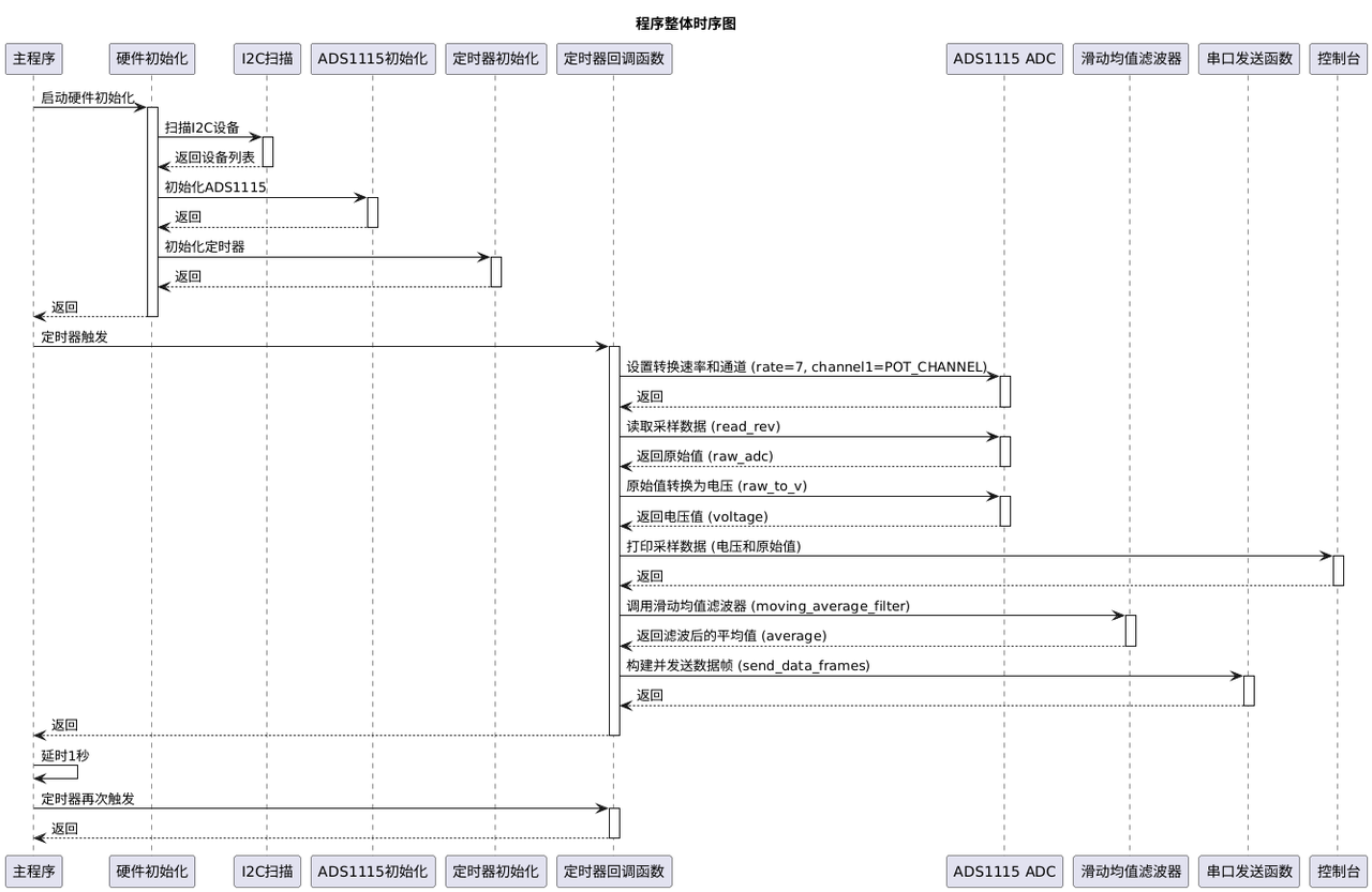
Inside timer‑callback routine:
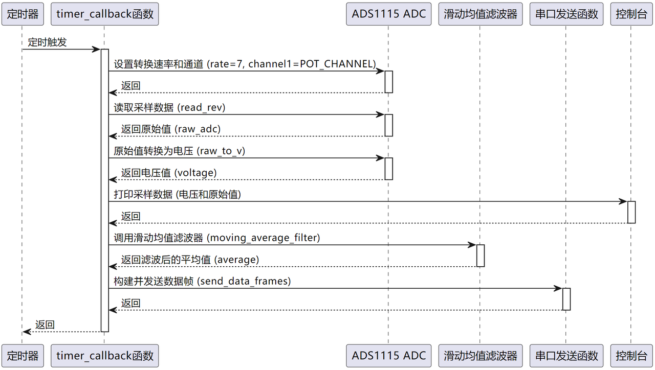
- Invoke
set_conv()to set ADS1115 data‑rate index to 7 (860 SPS) and input channel AIN0. - Call
read_rev()to fetch latest ADC sample and start next conversion cycle. - Convert raw ADC reading to physical voltage; print channel‑voltage and raw integer values to terminal.
- Invoke moving‑average filter function to smooth raw samples and reduce noise.
- Build binary data frame and transmit over UART for host‑side reception and processing.
Moving‑average filter logic inside moving_average_filter: append new reading to filter_buffer, accumulate sum into filter_sum. When buffer length exceeds FILTER_SIZE, pop oldest entry and subtract its value from running sum. Return integer‑division average result to produce smoothed output.
In send_data_frames: construct frame header 0xAA 0xBB, pack raw ADC value and filtered average as two little‑endian 16‑bit integers via struct.pack, concatenate header and payload bytes into complete serial frame.
Before flashing firmware configure SerialPlot software:
- Port tab: select correct COM port (example COM5), baud rate 256000, 8 data bits, 1 stop bit, no parity.
- Click “Open” button on upper‑right corner to open serial‑port connection.

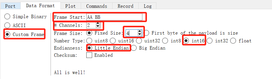
- Data‑Format tab: choose “Custom Frame”. Frame header bytes
0xAAand0xBB, channel count = 2, frame size fixed at 4 bytes, data type signed 16‑bit integer, little‑endian byte order.
Overall program‑flow diagram:
Flash firmware and open serial terminal:
Valid channel‑voltage readings print to console:
Waveform changes appear as signal‑generator output is adjusted:
Red trace shows raw waveform from DDS signal‑generator; blue trace is filtered smoothed waveform. Filtered output exhibits less noise but slower response speed. Important constraints: timer trigger rate must not exceed configured ADS1115 sampling rate, otherwise sampling errors may occur. Timer‑driven sampling rate equals timer frequency. According to Nyquist sampling theorem, input‑signal frequency from signal generator must be less than half of ADS1115 sampling rate.
- Interrupt‑triggered ADS1115 Sampling
The following example uses external‑interrupt trigger for ADS1115 data acquisition. Firmware communicates with ADC chip via I2C, applies moving‑average filtering to raw ADC samples. When ADS1115 completes conversion, the ALERT pin asserts and fires MCU interrupt. The interrupt service routine reads ADC result, converts reading to voltage and transmits raw and filtered readings over UART.
Hardware wiring is mostly identical to timer‑triggered example, except that ADS1115 ALERT interrupt‑output pin connects to GP13 for interrupt triggering.
Source code is located inside resource package under elegance‑devkit v1\Demo\61 ADC_ADS1115_IrqTrigger.
Sample code:
# Python env   : MicroPython v1.23.0
# -*- coding: utf-8 -*-
# @Time    : 2024/10/7 2:21 PM
# @Author  : Li Qingshui
# @File    : main.py
# @Description : ADC experiment, acquire data with external ADS1115 ADC chip using interrupt‑triggered sampling
# ======================================== Import related modules ========================================
# Import hardware‑related modules
from machine import Pin, I2C, UART
# Import time‑related modules
import time
# Import external ADC driver
from ads1115 import ADS1115
# Import struct for binary‑data packing / unpacking
import struct
# ======================================== Global variables ============================================
# External ADC I2C address
ADC_ADDRESS = 0
# Channel connected to potentiometer: AIN0
POT_CHANNEL = 0
# Moving‑average filter parameters
FILTER_SIZE   = 3
filter_buffer = []
filter_sum = 0
# ======================================== Function definitions ============================================
def send_data_frames(raw_adc: int, average: int) -> None:
    """
    Serial‑port transmit function for raw ADC reading and filtered average value.
    Args:
        raw_adc (int): Raw ADC sample reading.
        average (int): Moving‑average filtered result.
    Returns:
        None: This function returns nothing.
    Raises:
        Exception: Exception raised if frame construction or transmission fails.
    """
    global uart
    try:
        # Build frame: header 0xAA 0xBB plus two little‑endian 16‑bit values
        frame_header = struct.pack('<2B', 0xAA, 0xBB)
        frame_data = struct.pack('<2H', raw_adc & 0xFFFF, average & 0xFFFF)
        frame_full = frame_header + frame_data
        uart.write(frame_full)
    except Exception as e:
        print("Error in send_data_frames:", e)

def moving_average_filter(new_value: int, filter_size: int) -> int:
    """
    Moving‑average filter function.
    Args:
        new_value (int): New incoming sample reading.
        filter_size (int): Filter window length.
    Returns:
        int: Current moving‑average output value.
    Notes:
        Uses global variables filter_buffer and filter_sum to maintain sliding‑window state.
    """
    global filter_buffer, filter_sum
    filter_buffer.append(new_value)
    filter_sum += new_value
    if len(filter_buffer) > filter_size:
        removed = filter_buffer.pop(0)
        filter_sum -= removed
    return filter_sum // len(filter_buffer)

def alert_callback(pin: Pin) -> None:
    """
    ALERT‑pin interrupt callback function.
    Args:
        pin (machine.Pin): Pin instance triggering interrupt.
    Returns:
        None: This function returns nothing.
    Raises:
        Exception: Exception raised during ADC reading or frame transmission.
    """
    global adc, POT_CHANNEL
    try:
        raw_adc = adc.alert_read()
        voltage = adc.raw_to_v(raw_adc)
        print(f"irq ADC value: Channel AIN{POT_CHANNEL}: {voltage:.4f} V (Raw: {raw_adc})")
        average = moving_average_filter(raw_adc, FILTER_SIZE)
        print(f"ADC value after filter: {average}")
        send_data_frames(raw_adc, average)
    except Exception as e:
        print("Error in alert_callback:", e)
# ======================================== Custom classes ============================================
# ======================================== Initialization ==========================================
# 3‑second power‑on stabilization delay
time.sleep(3)
print("FreakStudio: Using ADS1115 acquire signal in interrupt mode")
# Create UART instance: baudrate 256000
uart = UART(0, 256000)
# Configure UART: 256000 baud, 8 data bits, no parity, 1 stop bit, TX=GPIO0, RX=GPIO1, timeout 100ms
uart.init(baudrate  = 256000,
          bits      = 8,
          parity    = None,
          stop      = 1,
          tx        = 0,
          rx        = 1,
          timeout   = 100)
# Create hardware I2C instance: I2C1, SDA=Pin2, SCL=Pin3, clock 400kHz
i2c = I2C(id=1, sda=Pin(2), scl=Pin(3), freq=400000)
# Scan I2C‑bus slave devices
devices_list = i2c.scan()
print('START I2C SCANNER')
if len(devices_list) == 0:
    print("No i2c device !")
else:
    print('i2c devices found:', len(devices_list))
    for device in devices_list:
        if 0x48 <= device <= 0x4B:
            print("ADC I2C hexadecimal address: ", hex(device))
            ADC_ADDRESS = device
# Create ADS1115 instance, gain = 1, assign alert‑pin number and interrupt callback
adc = ADS1115(i2c, ADC_ADDRESS, 1, alert_pin=4, callback=alert_callback)
# ======================================== Main program ===========================================
# Start ADS1115 continuous conversion with ALERT/RDY ready‑signal interrupt mode
adc.conversion_start(4,POT_CHANNEL)
# Infinite main‑program loop
while True:
    time.sleep(1)
Operating principle:
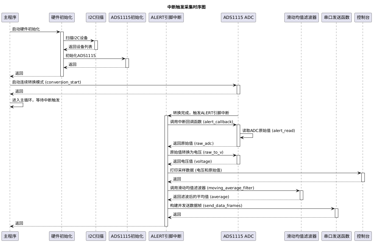
- Call
adc.conversion_start()to configure sampling channel and enable continuous‑conversion mode. ADS1115 asserts ALERT pin whenever a new conversion result becomes available. - ALERT‑pin hardware interrupt triggers
alert_callback(). Inside callbackalert_read()fetches ADC sample, converts raw reading to voltage, prints debug information, runs moving‑average filter and invokes frame‑transmission function.
Before flashing firmware configure SerialPlot:
- Port tab: select correct COM port (example COM5), baud rate 256000, 8 data bits, 1 stop bit, no parity.
- Click “Open” button at upper‑right corner to open serial‑port connection.

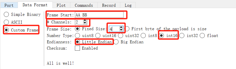
- Data‑Format tab: choose “Custom Frame”. Frame header bytes
0xAAand0xBB, channel count = 2, fixed frame‑size = 4 bytes, data type signed 16‑bit integer, little‑endian byte order.
Flash firmware and open serial terminal:
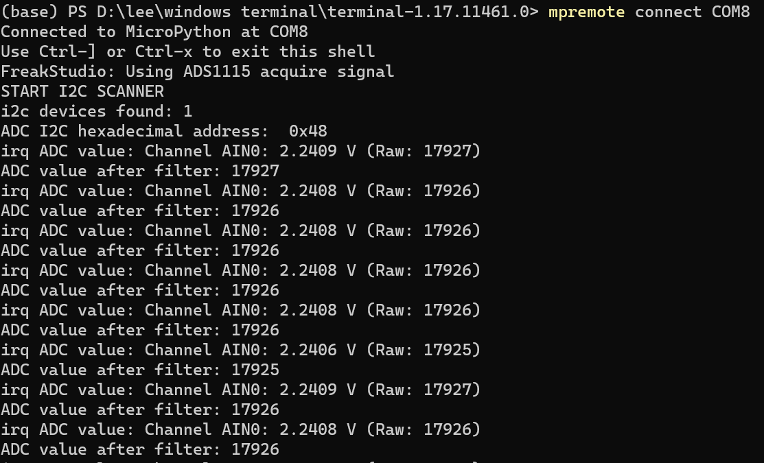
Valid channel‑voltage readings output to console:
Waveform varies as signal‑generator settings are adjusted:
Red trace represents raw signal‑generator waveform; blue trace is filtered waveform. Under interrupt‑driven sampling mode, effective sampling rate equals configured ADS1115 conversion rate.