Embedded 101: MCU Power-Up State Machine Explained via RP2040
This article introduces RP2040's power-on finite-state machine, its hardware sequential startup flow and controlled modules during chip power-up.
COMPONENTS
PROJECT DESCRIPTION
【Preliminary Note】The original hardware example in this article was written based on the RP2040. The actual hardware used in this hands-on demonstration features the W55RP20 as the main controller chip. The circuit logic and UF2 flashing operation principles are universally applicable, with only the main controller model differing. The original chip model mentioned in the circuit descriptions below is provided for reference purposes only.
Power-on finite-state machine
The power-on finite-state machine can be understood as the automatic startup wizard after a chip is powered on or reset. It is a pure hardware automated program responsible for "waking up" various hardware modules in the chip (such as the clock, storage, and processor) in a fixed sequence. Just as a computer must first start the power supply, then the motherboard, hard drive, and graphics card, and finally the CPU when booting up, the hardware of a chip must also be started in the correct order to avoid issues. The power-on finite-state machine is precisely responsible for this "sequential wake-up" task, operating fully automatically throughout the entire process without any intervention from software.
The power-on finite-state machine releases the reset state from various hardware blocks in a specific sequence. Each peripheral in the power-on finite-state machine is controlled by the internal rst_n/reset signal, and generates an internal rst_done high-active reset completion signal. The power-on finite-state machine releases the reset for each peripheral, and after waiting for the peripheral to generate the rst_done signal, proceeds to release the reset for the next peripheral.
When the chip's reset subsystem confirms that the digital core power supply (DVDD) is stable and RUN is at a high level, the power-on finite-state machine itself exits the reset state.
The power-on finite-state machine outputs signals via rst_n_run to reset many other blocks. This is typically used in applications that require a restart during initial startup but cannot be reset when the power-on finite-state machine restarts (i. e., modules that need to keep running continuously), for example:
Power-on of Logic in Ring Oscillators and Crystal Oscillators
the clock dividers (clk_ref and clk_sys) that must continue operating during the power-up finite-state machine restart
Watchdog Timer
These modules will not be reset when the finite-state machine restarts, ensuring that the basic functions keep working properly.
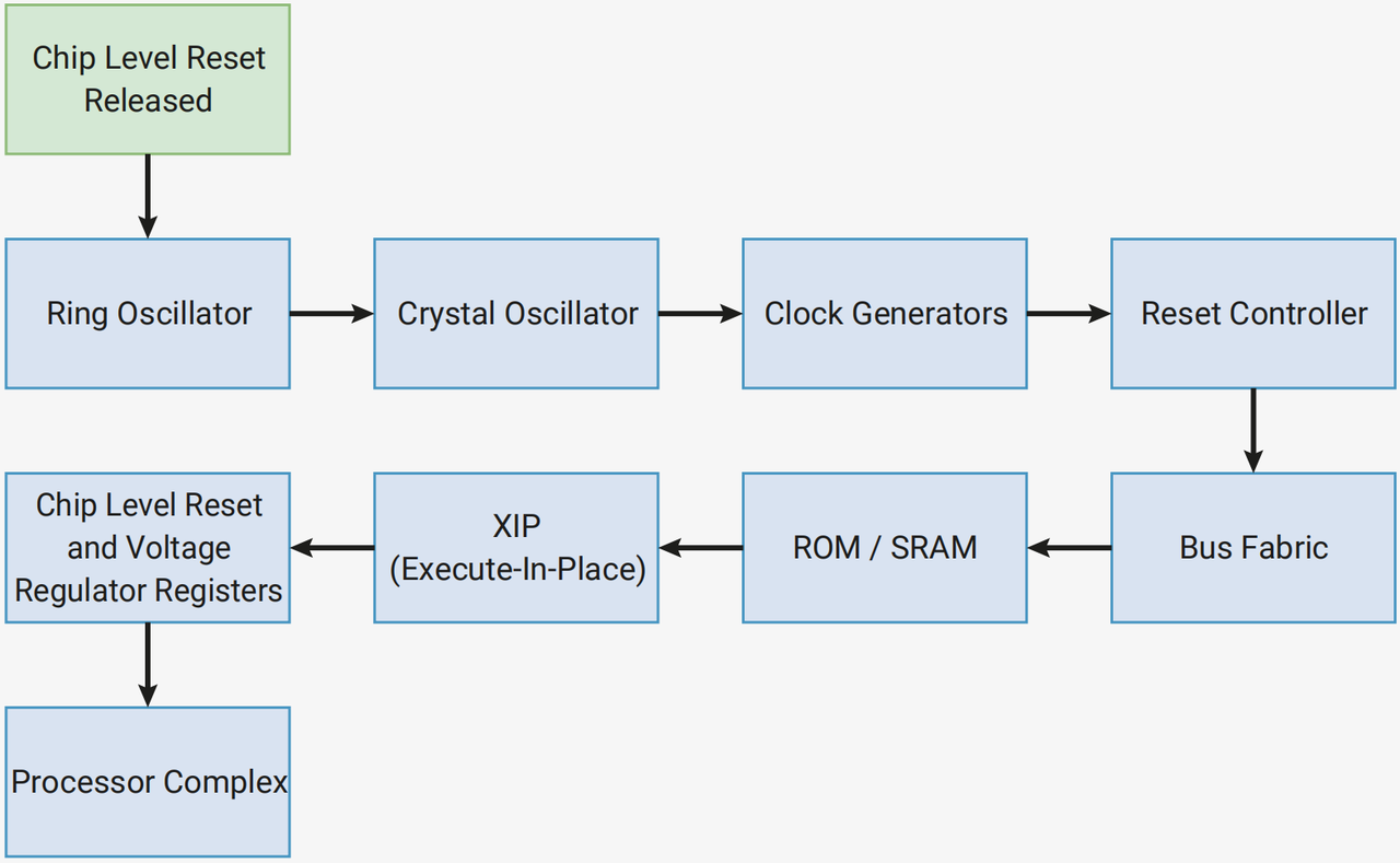
The power-on finite-state machine restart sequence is as follows:
Figure 2.36 Block diagram of the chip power-on finite-state machine startup process
We can see that its wake-up sequence goes from the "most basic hardware" to the "core components", and the process is as follows:
Start the ring oscillator first (it provides the most basic initial clock, which is equivalent to establishing a "heartbeat" first);
Restart Crystal Oscillator (provides a more accurate clock, replacing the basic clock);
Then start up the clock generator (to distribute the clock to each module);
Next comes the reset controller (which manages the reset status of subsequent modules);
then activates the bus architecture (the "channels" for data transmission between individual modules);
re-awaken ROM/SRAM (where programs and data are stored);
Next comes XIP (the function of accessing external Flash, which enables the chip to read external storage);
Next come the chip-level reset and voltage regulator registers (which manage the configuration of power supply and reset);
Finally wake up the processor core (the CPU, the "brain" of the chip).
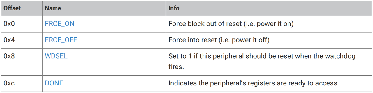
The power-on finite-state machine is a fully automated hardware component. It can operate without any input from the user. There are several register controls available to override and view the status of the power-on finite-state machine, which allows the hardware blocks within the power-on finite-state machine to be reset via software when necessary.
The base address of the PSM register of the power-on finite-state machine is 0x40010000.
Figure 2.37 Architecture Diagram of the RP2040 Chip Clock System