



MCP4725 Waveform Generator: MicroPython Code, Timer Driver & Debug Guide
MCP4725 waveform generator MicroPython timer‑driven implementation and debugging process
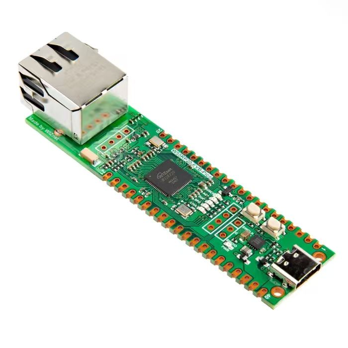
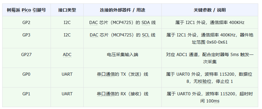
The code below runs on Raspberry‑Pi Pico, it uses the DAC chip MCP4725 to generate various waveform signals, and outputs ADC‑sampled waveform voltage values over serial port. Component wiring is identical to the previous section.
Source code can be found in the resource package under elegance‑devkit v1\Demo\63 DAC_WaveformGenerator.
Sample code:
# Python env   : MicroPython v1.23.0
# -*- coding: utf-8 -*-
# @Time    : 2024/9/1 2:10 PM
# @Author  : Li Qingshui
# @File    : main.py
# @Description : DAC experiment, generate different waveforms using external DAC chip
# ======================================== Import related modules ========================================
# Import hardware‑related modules
from machine import ADC, Timer, Pin, I2C, UART
# Import time‑related modules
import time
# Import MicroPython internal‑structure access module
import micropython
# Import math library for waveform calculation
import math
# Import mcp4725 module for DAC chip control
from mcp4725 import MCP4725
# ======================================== Global variables ============================================
# MCP4725 chip address
DAC_ADDRESS = 0x00
# Voltage conversion factor
adc_conversion_factor = 3.3 / (65535)
# ======================================== Function definitions ============================================
def timer_callback(timer: Timer) -> None:
    """
    Timer callback function for periodic ADC reading and invoking user‑defined callback.
    Args:
        timer (machine.Timer): Timer instance.
    Returns:
        None: This method returns nothing.
    Raises:
        None: This method raises no exceptions.
    """
    global adc,adc_conversion_factor
    # Read ADC sample data
    value = adc.read_u16() * adc_conversion_factor
    # Invoke user‑defined callback function
    micropython.schedule(user_callback, (value))

def user_callback(value: float) -> None:
    """
    User‑defined callback function to process ADC‑sampled voltage and send data over serial port.
    Args:
        value (float): Voltage value sampled by ADC.
    Returns:
        None: This method returns nothing.
    Raises:
        None: This method raises no exceptions.
    """
    global uart
    # Round float value to two decimal places
    formatted_value = "{:.2f}".format(value)
    # Send sampled voltage over serial port
    uart.write(str(formatted_value) + '\r\n')

# ======================================== Custom classes ============================================
# Waveform generator class for generating voltage signals of different shapes
class WaveformGenerator:
    """
    Waveform generator class for generating different voltage‑signal waveforms.
    This class generates sine, square and triangle waveforms via DAC chip such as MCP4725.
    Parameters such as frequency, amplitude and DC offset are configurable.
    Waveform samples are sent periodically to DAC by timer interrupt to produce continuous output.
    Attributes:
        dac (MCP4725): DAC chip instance used for waveform output.
        frequency (float): Signal frequency in Hz.
        amplitude (float): Signal amplitude in Volts.
        offset (float): DC offset in Volts.
        waveform (str): Waveform type, supports 'sine', 'square', 'triangle'.
        rise_ratio (float): Triangle‑wave rise‑slope ratio, range 0 to 1.
        sample_rate (int): Fixed sample count, 50 samples.
        dac_resolution (int): DAC resolution, 12‑bit range 0‑4095.
        samples (list[int]): List of pre‑computed sample points.
        index (int): Current sample index for sequential output.
        timer (Timer): Timer instance for periodic waveform output trigger.
    Methods:
        __init__(dac, frequency=1, amplitude=1.65, offset=1.65, waveform='sine', rise_ratio=0.5):
            Initialize waveform‑generator instance.
        generate_samples() -> list[int]:
            Generate sample‑point array according to selected waveform.
        update(t: Timer) -> None:
            Timer callback, output next sample point.
        start() -> None:
            Start waveform generator.
        stop() -> None:
            Stop waveform generator.
    """
    def __init__(self, dac: 'MCP4725', frequency: float = 1, amplitude: float = 1.65, offset: float = 1.65,
                 waveform: str = 'sine', rise_ratio: float = 0.5) -> None:
        """
        Initialize waveform‑generator instance.
        Sets basic parameters: DAC object, signal frequency, amplitude, DC offset, waveform type and triangle‑wave rise ratio.
        Args:
            dac (MCP4725): DAC chip instance for waveform generation.
            frequency (float, optional): Signal frequency, default 1 Hz. Must be greater than 0 and ≤10 Hz.
            amplitude (float, optional): Signal amplitude, default 1.65V. Must be between 0 and 3.3V.
            offset (float, optional): DC offset voltage, default 1.65V. Must be between 0 and 3.3V.
            waveform (str, optional): Waveform type: 'sine', 'square', 'triangle'. Default 'sine'.
            rise_ratio (float, optional): Triangle‑wave rise‑edge ratio, default 0.5, valid 0‑1.
        Returns:
            None: This method returns nothing.
        Raises:
            ValueError: Raised when input parameters are out of valid ranges.
        """
        # Parameter validation
        if not (0 < frequency <= 10):
            raise ValueError("Frequency must be between 0 and 10 Hz.")
        if not (0 <= amplitude <= 3.3):
            raise ValueError("Amplitude must be between 0 and 3.3V.")
        if not (0 <= offset <= 3.3):
            raise ValueError("Offset must be between 0 and 3.3V.")
        if not(0 <= amplitude+offset <= 3.3):
            raise ValueError("Amplitude + offset must be between 0 and 3.3V.")
        if waveform not in ['sine', 'square', 'triangle']:
            raise ValueError("Waveform must be 'sine', 'square', or 'triangle'.")
        if not (0 <= rise_ratio <= 1):
            raise ValueError("Rise ratio must be between 0 and 1.")

        # Store DAC instance
        self.dac = dac
        # Initialize software‑timer; ‑1 means not bound to hardware timer on creation
        self.timer = Timer(-1)
        # Save waveform‑generator parameters
        self.frequency = frequency
        self.amplitude = amplitude
        self.offset = offset
        self.waveform = waveform
        self.rise_ratio = rise_ratio
        # Fixed sample‑point count for discrete waveform
        self.sample_rate = 50
        # 12‑bit DAC output range: 0‑4095
        self.dac_resolution = 4095
        # Generate sample‑point data according to waveform selection
        self.samples = self.generate_samples()
        # Current sample index for sequential output
        self.index = 0

    def generate_samples(self) -> list[int]:
        """
        Generate sample‑point array for selected waveform.
        Computes sample values and converts each sample into DAC‑compatible integer codes.
        Returns:
            list[int]: List of DAC integer sample codes.
        Raises:
            None: This method raises no exceptions.
        """
        # Helper: convert voltage to DAC code
        def to_dac_value(voltage):
            return int(voltage / 3.3 * self.dac_resolution)
        samples = []
        if self.waveform == 'sine':
            for i in range(self.sample_rate):
                angle = 2 * math.pi * i / self.sample_rate
                voltage = self.offset + self.amplitude * math.sin(angle)
                samples.append(to_dac_value(voltage))
        elif self.waveform == 'square':
            for i in range(self.sample_rate):
                if i < self.sample_rate // 2:
                    voltage = self.offset + self.amplitude
                else:
                    voltage = self.offset - self.amplitude
                samples.append(to_dac_value(voltage))
        elif self.waveform == 'triangle':
            for i in range(self.sample_rate):
                if i < self.sample_rate * self.rise_ratio:
                    voltage = self.offset + 2 * self.amplitude * (
                            i / (self.sample_rate * self.rise_ratio)) - self.amplitude
                else:
                    voltage = self.offset + 2 * self.amplitude * (
                            (self.sample_rate - i) / (self.sample_rate * (1 - self.rise_ratio))) - self.amplitude
                samples.append(to_dac_value(voltage))
        return samples

    def update(self, t: Timer) -> None:
        """
        Timer callback. Writes next sample point to DAC on timer interrupt.
        Args:
            t (Timer): Timer object triggering this callback.
        Returns:
            None: This method returns nothing.
        Raises:
            None: This method raises no exceptions.
        """
        self.dac.write(self.samples[self.index])
        self.index = (self.index + 1) % self.sample_rate

    def start(self) -> None:
        """
        Start waveform generator, enable periodic timer for sample output.
        Returns:
            None: This method returns nothing.
        Raises:
            None: This method raises no exceptions.
        """
        self.timer.init(freq=self.frequency * self.sample_rate, mode=Timer.PERIODIC, callback=self.update)

    def stop(self) -> None:
        """
        Stop waveform generator, disable timer and reset sample index.
        Returns:
            None: This method returns nothing.
        Raises:
            None: This method raises no exceptions.
        """
        self.timer.deinit()
        self.index = 0

# ======================================== Initialization ==========================================
# 3‑second power‑on stabilization delay
time.sleep(3)
# Print debug information
print("FreakStudio : Using DAC to generate differential waveform")
# Create hardware I2C instance: I2C1, 400kHz, SDA=Pin2, SCL=Pin3
i2c = I2C(id=1, sda=Pin(2), scl=Pin(3), freq=400000)
# Scan I2C‑bus slave devices
devices_list = i2c.scan()
print('START I2C SCANNER')
if len(devices_list) == 0:
    print("No i2c device !")
else:
    print('i2c devices found:', len(devices_list))
    for device in devices_list:
        if 0x60 <= device <= 0x61:
            print("I2C hexadecimal address: ", hex(device))
            DAC_ADDRESS = device
# Create DAC object
dac = MCP4725(i2c, DAC_ADDRESS)
# Read DAC configuration
eeprom_write_busy, power_down, value, eeprom_power_down, eeprom_value = dac.read()
print(eeprom_write_busy, power_down, value, eeprom_power_down, eeprom_value)
# Configure DAC: disable power‑down, output 0V, write settings to EEPROM
dac.config(power_down='Off',value=0,eeprom=True)
# 50 ms delay; immediate read after configuration causes errors
time.sleep_ms(50)
# Read DAC configuration again
eeprom_write_busy, power_down, value, eeprom_power_down, eeprom_value = dac.read()
print(eeprom_write_busy, power_down, value, eeprom_power_down, eeprom_value)
# Create UART instance, baudrate 115200
uart = UART(0, 115200)
uart.init(baudrate  = 115200,
          bits      = 8,
          parity    = None,
          stop      = 1,
          tx        = 0,
          rx        = 1,
          timeout   = 100)
# Create ADC instance: ADC1‑GP27
adc = ADC(1)
# Create software‑timer for ADC sampling
timer = Timer(-1)
# Trigger timer_callback every 1 ms for ADC voltage acquisition
timer.init(period=1, mode=Timer.PERIODIC, callback=timer_callback)

# ======================================== Main program ===========================================
# Generate sine wave
print("FreakStudio : Generate Sine Waveform : 10Hz, 1.5V, 1.5V")
wave = WaveformGenerator(dac, frequency=10, amplitude=1.5, offset=1.5, waveform='sine')
wave.start()
time.sleep(5)
wave.stop()

# Generate square wave
print("FreakStudio : Generate Square Waveform : 10Hz, 1.5V, 1.5V")
wave = WaveformGenerator(dac, frequency=10, amplitude=1.5, offset=1.5, waveform='square')
wave.start()
time.sleep(5)
wave.stop()

# Generate triangle wave
print("FreakStudio : Generate Triangle Waveform : 10Hz, 1.5V, 1.5V, 0.8")
wave = WaveformGenerator(dac, frequency=10, amplitude=1.5, offset=1.5, waveform='triangle', rise_ratio=0.8)
wave.start()
time.sleep(5)
wave.stop()

# Stop ADC sampling timer
timer.deinit()
We implemented a custom WaveformGenerator class to produce frequency‑ and amplitude‑adjustable square, sine and triangle waveforms and output them to DAC.
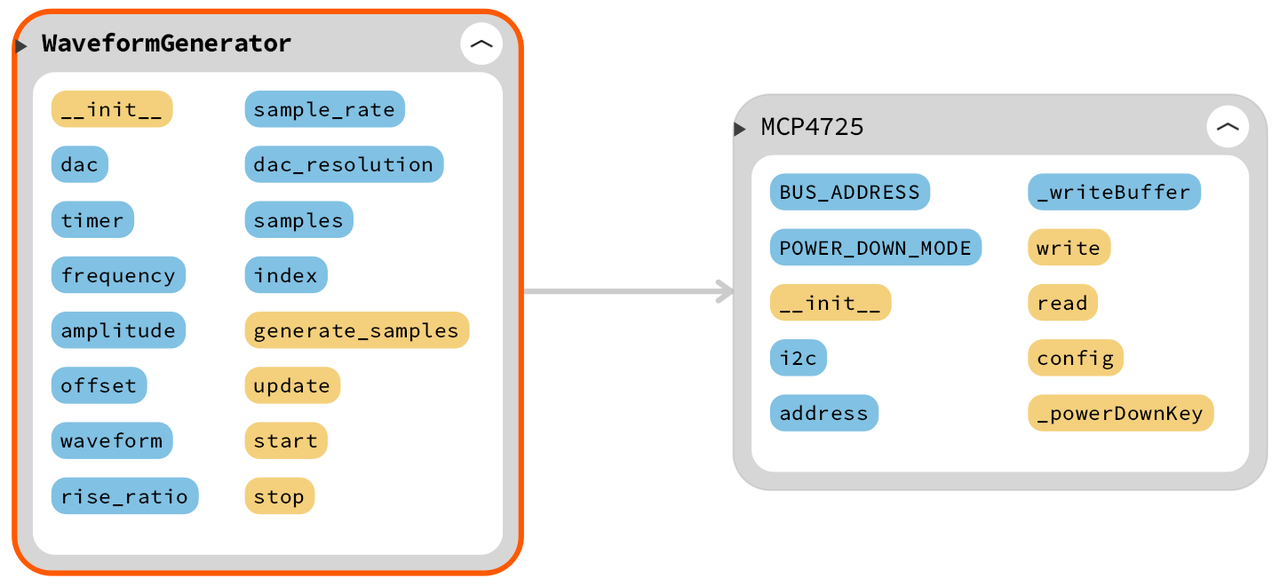
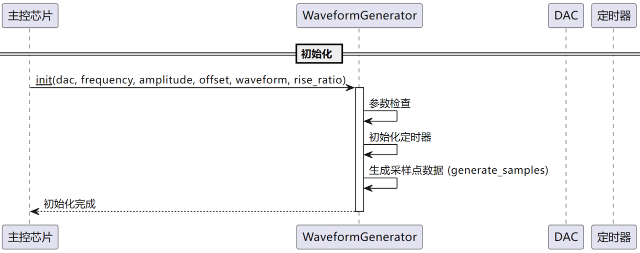
- In constructor method, validate input parameters (frequency, amplitude, offset, waveform type etc.) to keep them within reasonable ranges. Store DAC handle and waveform parameters, initialize timer object, call
generate_samplesto pre‑compute sample‑point array from given waveform settings.
- Inside
generate_samplesmethod compute sample‑point values for selected waveform:- Sine wave: generate samples using
math.sin. - Square wave: produce alternating high‑level / low‑level samples according to sample index.
- Triangle wave: generate linearly‑changing samples for rising‑edge and falling‑edge segments. Return completed sample‑point list.
- Sine wave: generate samples using
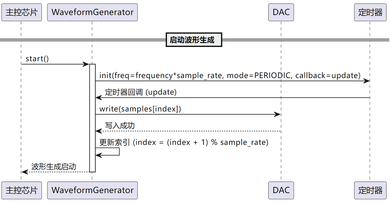
- In timer‑callback
updatemethod: write current sample value to DAC, increment sample index and wrap‑around to loop through sample array.
- After instantiating
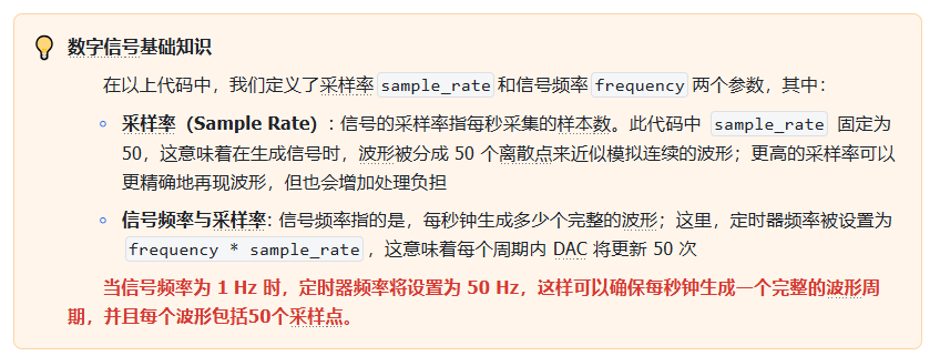
WaveformGenerator, invokestart()to initialize timer with frequencyself.frequency * self.sample_rateand periodically executeupdate(). Callstop()to halt timer and reset sample index to zero.
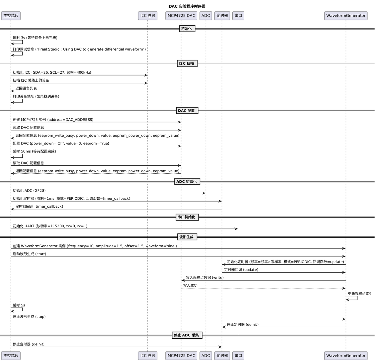
In main program three WaveformGenerator instances are created sequentially for sine‑wave, square‑wave and triangle‑wave (rise‑ratio 0.8). Each waveform runs for 5 seconds then stops. After all waveforms complete, the ADC‑sampling timer is de‑initialized.
Overall program timing‑sequence diagram:
Launch SerialPlot software, select correct COM port for USB‑to‑TTL adapter and click Open.

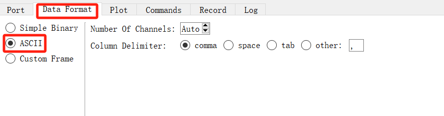
Select ASCII for data format, keep other options as default.

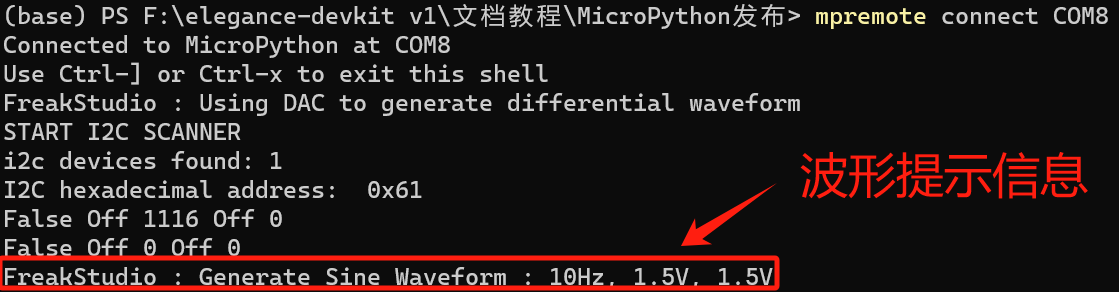
Flash firmware and open serial terminal, example output:
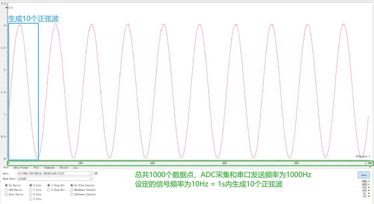
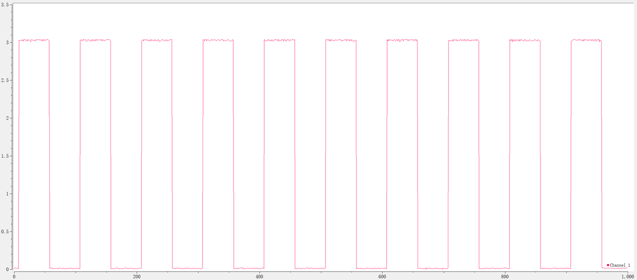
Inside SerialPlot you can observe DAC‑output waveforms with correct frequency and amplitude.
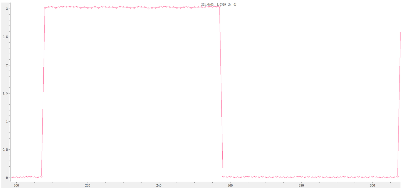
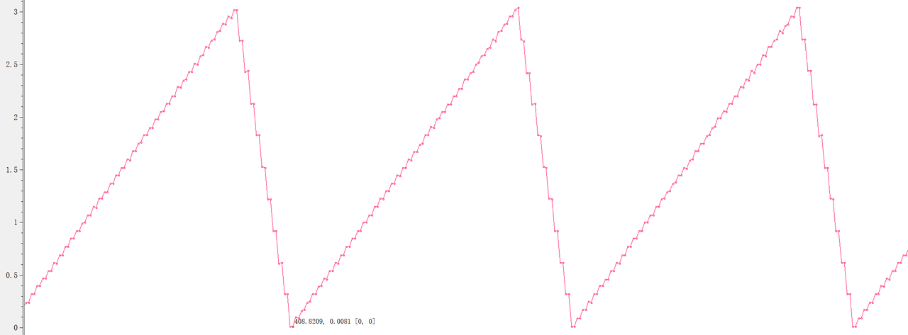
Compared with DDS signal‑generator chips, waveform generation using MCP4725 DAC requires the microcontroller to compute every waveform sample in software and send each point one‑by‑one to DAC. This increases system complexity and consumes more CPU resources. Frequent timer interrupts occur at higher output frequencies; large sample‑point buffers consume significant RAM. Waveform frequency is completely limited by microcontroller DAC‑update speed. Frequency precision and resolution are bounded by MCU clock and timer granularity. Under MicroPython, practical maximum update rate for software timers is 1000 Hz, greatly limiting achievable signal frequency range.
Moreover MCP4725 communicates over I²C bus. Bus congestion or other MCU background tasks can introduce jitter and instability in output waveforms. For real‑world projects, dedicated external DDS chips are generally preferred for waveform‑generation tasks.