Master RP2040 Pin Reuse in 1 Minute: Pin Saving, Flexible Design, the "Cost-Saving Hack" for hardwar
This article defines pin multiplexing and explains how RP2040 GPIOs switch between different peripheral functions via function selection tables.
COMPONENTS
PROJECT DESCRIPTION
Pin function to reuse
Put simply, pin multiplexing means "one GPIO pin can serve multiple roles" — for example, a single GPIO pin can function as an ordinary switch (to control the on/off state of an LED), or be switched to act as an "SPI interface"(to connect to a sensor) or a "UART interface"(to connect to a serial port). This is just like a phone's Type-C port, which can not only charge the device but also transfer data and connect to other peripherals: one interface delivering multiple functions, and this is exactly what "to reuse" refers to.
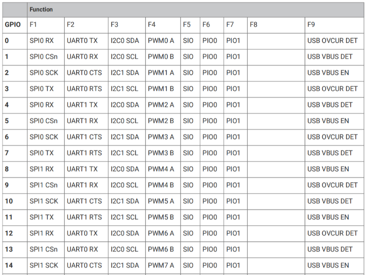
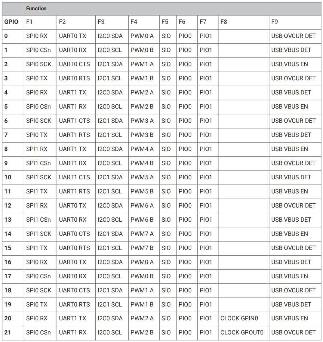
Each individual GPIO pin can be connected to an internal peripheral via the GPIO functions defined below:
Figure 2.6 RP2040 GPIO Pin Function Table (Pins 0-21)
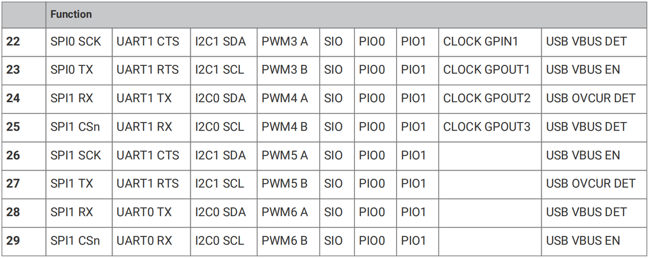
Figure 2.7 RP2040 GPIO Pin Function Multiplexing Table (22-29)
This table is the " GPIO Role Selection Table", and its structure and usage are very simple:
The first column (GPIO number): refers to the specific GPIO pins (e. g., GPIO0, GPIO1), with each pin corresponding to one row;
Columns F1 to F9 (function options): represent the "roles" that this GPIO can switch between (for example, F1 corresponds to SPI0 RX, and F2 corresponds to UART0 TX) — each GPIO can select one function from these options for use, and only one function can be selected at a time;
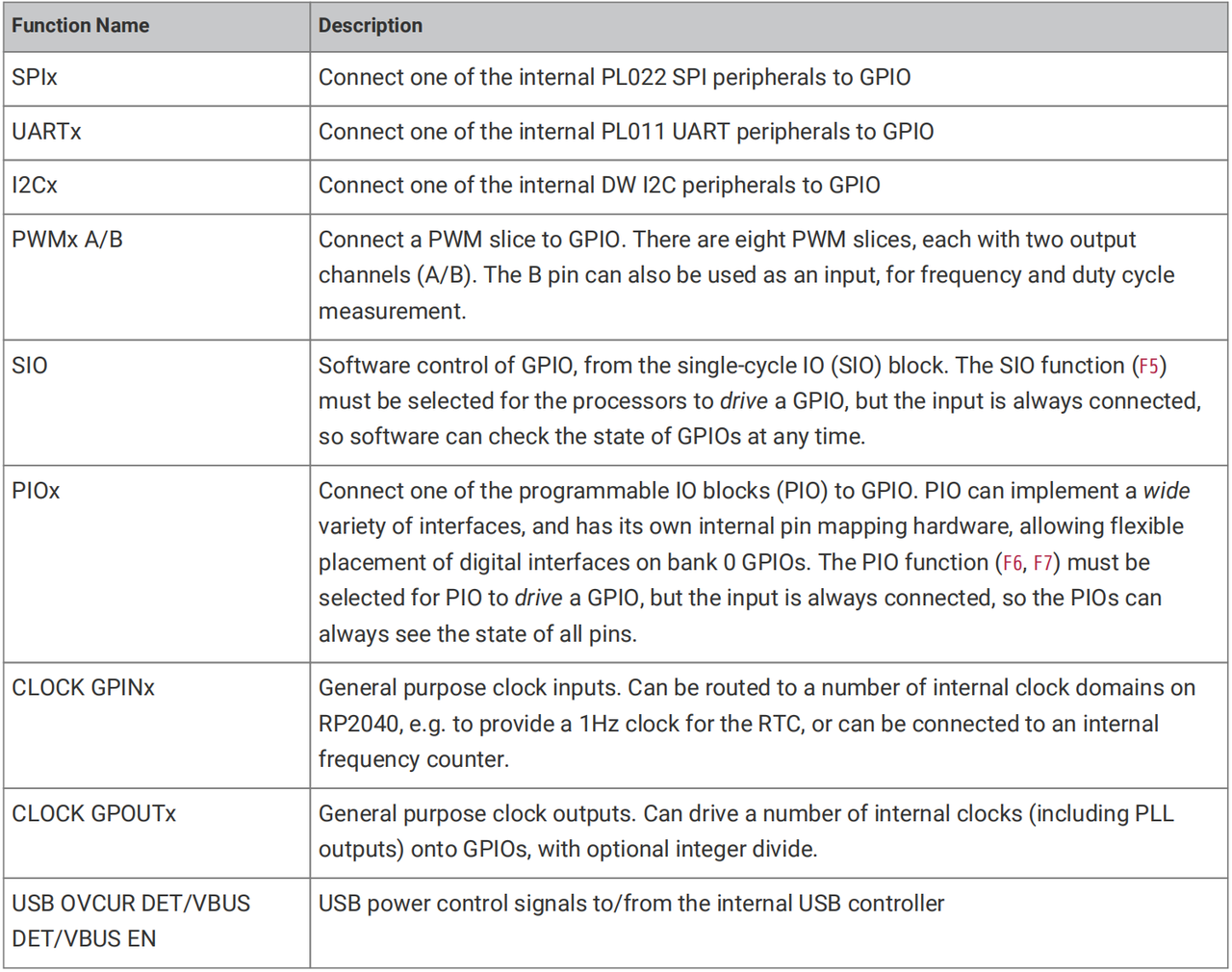
Figure 2.8 RP2040 Pin Function Multiplexing Description Table
The function description table above explains the internal components of the chip corresponding to each "role"(for example, SPIx corresponds to the SPI controller in the chip, and UARTx corresponds to the UART controller), as well as the purpose of each function.