



Low‑Power Modes Deep Dive: From General Principles to Pico RP2040 Register Configuration
In‑depth explanation of microcontroller low‑power theory and RP2040 register‑level configuration for Raspberry Pi Pico.
- Low‑Power Modes
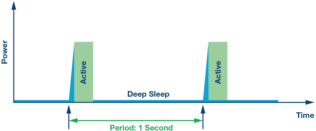
In microcontroller applications, low‑power modes are a set of operating states designed to reduce system power consumption, extend battery life or lower energy usage. These modes achieve low‑power operation by lowering clock frequencies, turning off unused peripherals and processor cores, or even entering deep‑sleep states.
1.1 Definition and principles of low‑power modes
Low‑power modes are operating modes where a microcontroller keeps certain essential functions such as timing, counting or external‑event monitoring active while reducing power draw. These modes are commonly used for battery‑powered devices such as IoT sensors, wearables and portable electronics to prolong battery runtime.
Power consumption is reduced through the following approaches:
Clock management Reduce power usage by lowering system‑clock frequency or stopping selected clock signals.
Peripheral management Shut down or suspend unused peripherals such as ADC, UART, I2C to cut their power draw.
Processor management Put the processor into low‑power states such as sleep or deep‑sleep to lower dynamic processor power consumption.
Power management Some microcontrollers support power gating for selected modules and peripherals, completely cutting their power supply to achieve ultra‑low static power consumption.
1.2 Types of microcontroller operating modes
From a power‑consumption perspective, microcontroller operating modes fall into these categories:
- Run Mode Definition This is the normal operating mode. All modules and peripherals are active, and the system runs at full clock frequency. Characteristics Highest power consumption, highest performance.
- Idle Mode Definition In idle mode, the CPU stops executing instructions while other peripherals and clocks remain active. Characteristics Lower power than run mode. Suitable while waiting for external events or interrupts.
- Sleep Mode Definition In sleep mode, the CPU stops execution and most peripherals enter low‑power states, while key peripherals such as timers and RTC keep running. Characteristics Further reduced power consumption. Used when the processor does not need to perform tasks temporarily.
- Deep Sleep Mode Definition In deep‑sleep mode, the CPU and most peripherals are turned off. Only a small set of peripherals such as RTC and RAM content are retained. Characteristics Extremely low power consumption. Used for long idle periods. Wake‑up is usually triggered by external interrupts or timers.
- Hibernate Mode Definition This is the lowest‑power mode. Most system modules and power domains are disabled. Only a minimal set of wake‑up sources such as RTC or external interrupts remain available. Characteristics Minimum static power draw. Used for very long sleep durations. System typically requires re‑initialization after wake‑up.
- Stop Mode Definition In stop mode, all clock signals are halted. Only dedicated wake‑up sources can bring the microcontroller out of this state. Characteristics Near‑zero dynamic power consumption and very low static power consumption. Suitable for long periods of inactivity.
1.3 Wake‑up mechanisms
Wake‑up mechanisms return the system from low‑power states such as sleep or hibernate back to normal run mode. Common wake‑up sources for microcontrollers include:
External interrupts External‑interrupt sources such as GPIO pins stay monitored during low‑power modes. When an interrupt condition is detected, an interrupt request is asserted and the system wakes from low‑power mode.
Timer A timer generates an interrupt after a predefined interval to wake the system. Timers keep running in low‑power states; upon timer expiry an interrupt signal is generated to wake the processor.
Real‑Time Clock The RTC runs with very low power consumption during low‑power modes. It raises an interrupt at scheduled times or periodic intervals to wake the system via RTC interrupt.
Internal events Certain internal events such as peripheral operation completion or data ready can also trigger wake‑up. Internal flags or registers generate an internal interrupt, waking the system.
- Low‑power modes on Raspberry Pi Pico
The RP2040 microcontroller provides multiple options for lowering dynamic and static power consumption, enabling higher energy efficiency for different use‑cases.
Dynamic‑power‑reduction options:
Top‑level clock gating Clock for individual peripherals and functional blocks can be turned on or off independently to eliminate unnecessary power draw.
Automatic clock gating Top‑level clock gating is controlled automatically according to processor sleep status. Unneeded clocks are disabled when the processor enters sleep.
Dynamically adjust system‑clock frequency or clock source For example, switch to internal oscillator and disable PLL and crystal oscillator to reduce power consumption.
Zero‑dynamic‑power dormant state In this state all clocks and oscillators are disabled. The system can be woken by GPIO events or RTC interrupts to resume normal operation.
Static‑power‑reduction options:
Memory low‑power retention mode Reduce memory power consumption while preserving stored data.
Peripheral power gating Peripherals such as ADC and temperature sensor support power gating. Their power supply can be turned off when unused to save power.
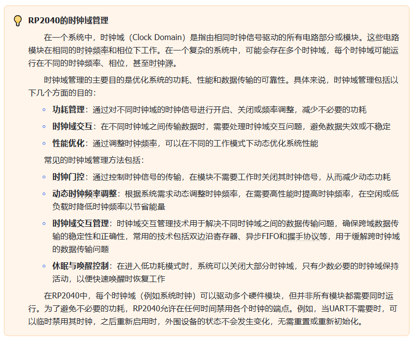
On RP2040 there are two low‑power states: SLEEP State and DORMANT State.
SLEEP State RP2040 enters SLEEP state when both Cortex‑M0+ cores execute WFI / WFE instructions and no DMA transfers are in progress. It exits SLEEP state when either core is woken by an interrupt.
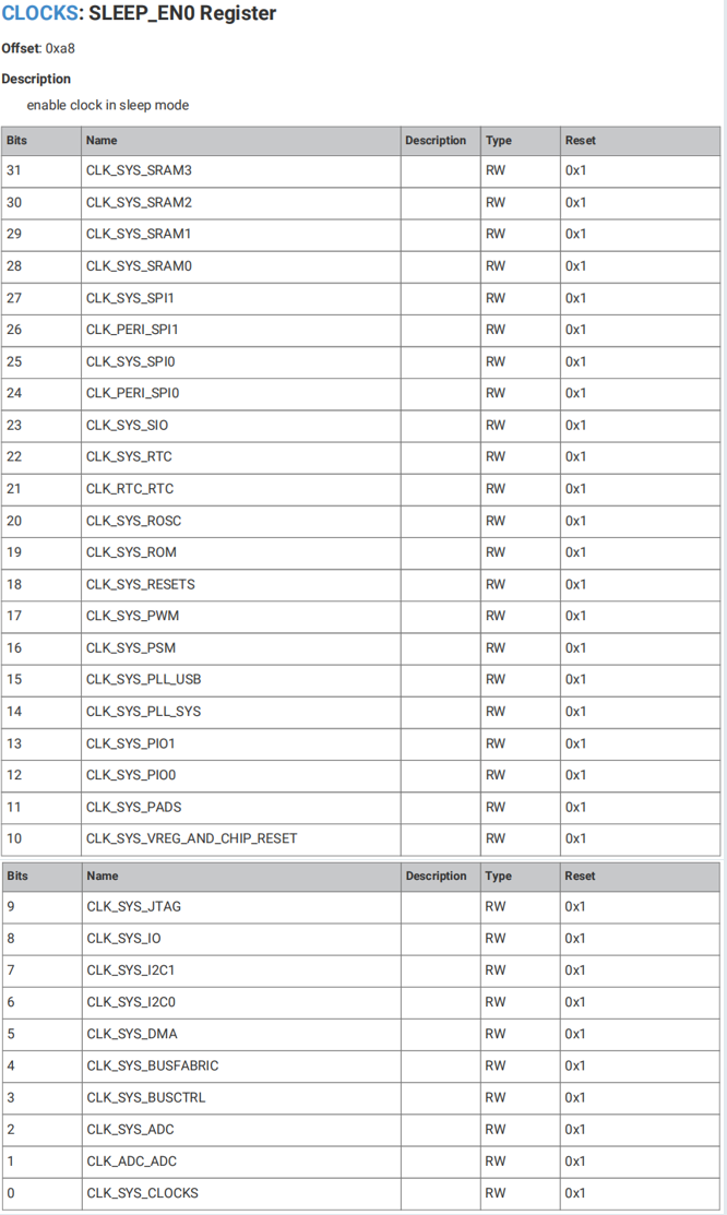
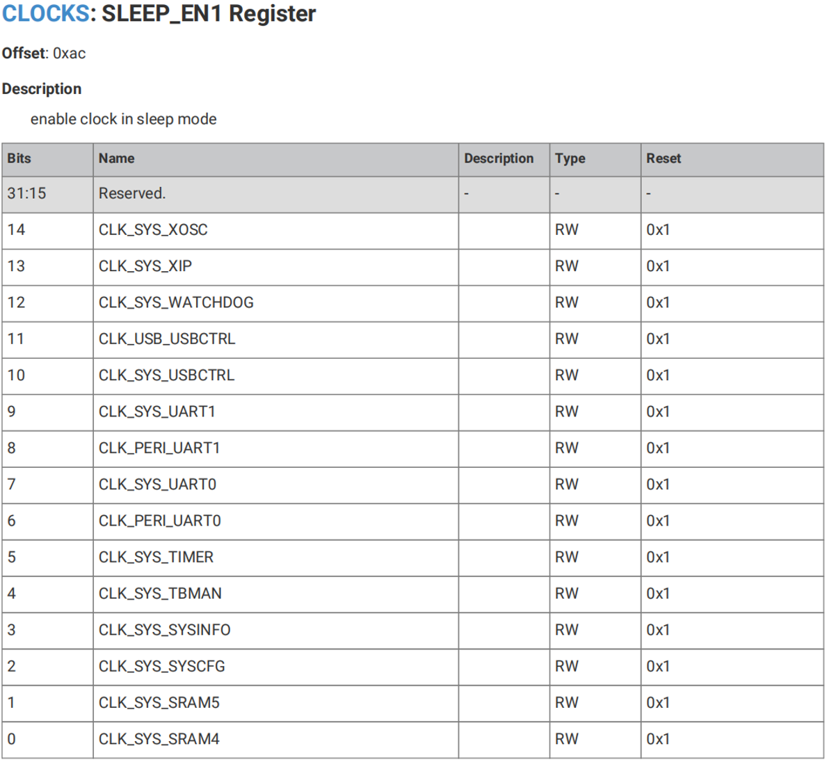
Clock management In SLEEP state, top‑level clock gating is controlled by SLEEP_ENx registers instead of WAKE_ENx registers. This allows aggressive clock‑tree cutting while processors are sleeping to save power.
Use‑case example If the system sleeps waiting for a UART character interrupt, most of the system except UART can be clock‑gated. A UART interrupt wakes the processor, the system leaves SLEEP state and switches back to the WAKE_ENx clock mask.
DORMANT State DORMANT is a true zero‑dynamic‑power sleep state. All clocks including oscillators are disabled. Wake‑up sources are GPIO events (high / low level, rising / falling edge) or RTC interrupt. After wake‑up an oscillator restarts, stabilises and releases its output; program execution resumes from the exact point before entering DORMANT without full system re‑initialization.
Clock management All clocks and oscillators are disabled in DORMANT. If RTC is used for wake‑up, RTC must have an external clock source. PLLs should be shut down before entering DORMANT to avoid extra power draw; PLLs need to be restarted and re‑configured after exiting DORMANT.
Use‑case example Ideal for long system idle periods requiring fast wake‑up, e.g. deep standby sleep.
Power consumption figures for Raspberry Pi Pico at 48 MHz operating frequency:
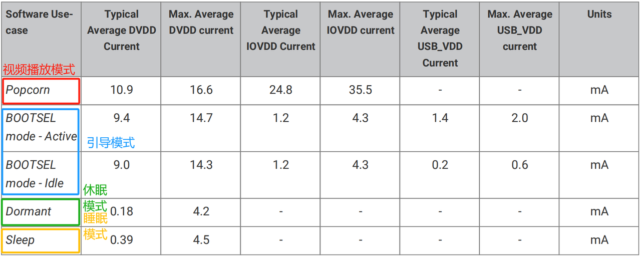
Key registers related to SLEEP and DORMANT modes:
SLEEP_ENx (SLEEP_EN0, SLEEP_EN1) registers These registers control clock‑domain enable / disable when processors enter SLEEP state. Bits in SLEEP_ENx specify which clocks remain active and which get turned off during sleep to eliminate wasted power.
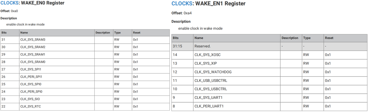
WAKE_ENx (WAKE_EN0, WAKE_EN1) registers These registers define which clock domains are enabled in normal wake state. When processors exit SLEEP state, the system switches to the clock configuration defined by WAKE_ENx to re‑enable required clock domains.
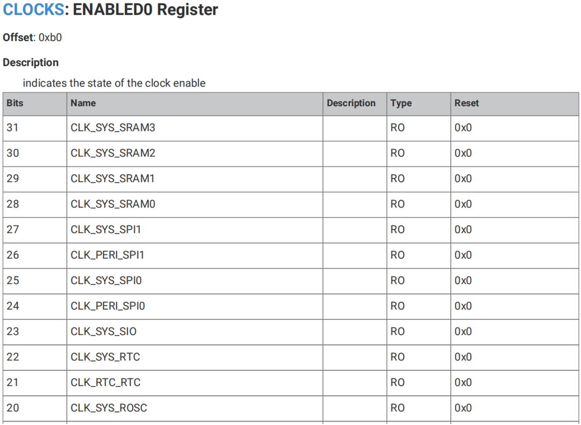
ENABLEDx (ENABLED0, ENABLED1) registers These registers reflect current enable status for each clock domain. They show which clock domains are enabled or disabled in the current state, whether SLEEP or WAKE.
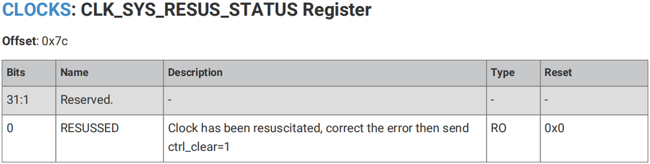
CLK_SYS_RESUS_CTRL and CLK_SYS_RESUS_STATUS registers These registers implement the system‑clock resuscitation function. When the system enters ultra‑low‑power states, they help manage re‑enabling system clocks to guarantee proper recovery.
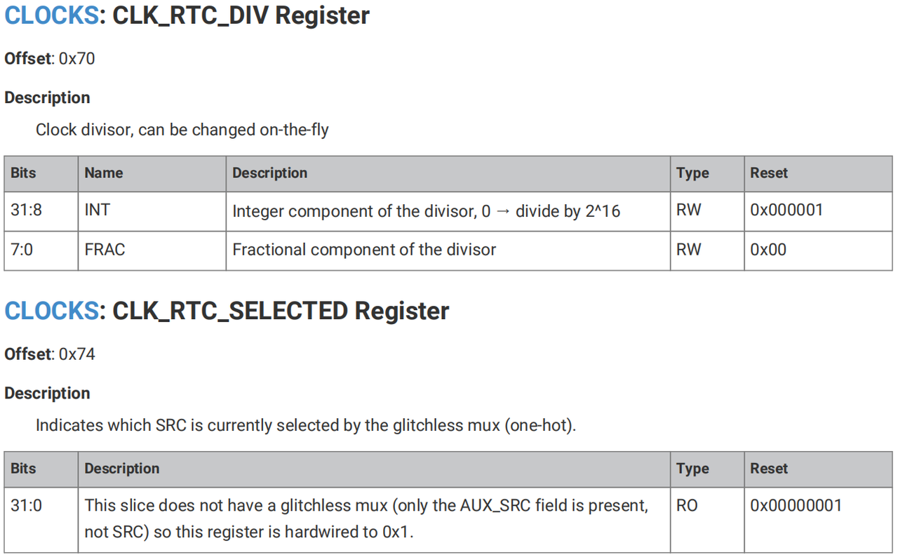
CLK_RTC_CTRL, CLK_RTC_DIV and CLK_RTC_SELECTED registers These registers configure RTC clock source selection and divider settings. If relying on RTC to wake from DORMANT state, these registers must be correctly set and RTC must be supplied with an external clock source.
DORMANT‑mode control Writing special key values to the DORMANT register puts the chip into true zero‑dynamic‑power DORMANT state. In this state all clocks and oscillators are disabled; wake‑up occurs only via GPIO events or RTC interrupts.
DORMANT_WAKE_INTEX registers enable wake‑up interrupt sources for DORMANT mode. DORMANT_WAKE_INTFx registers force assertion of DORMANT wake‑up interrupts. DORMANT_WAKE_INTSx registers show status flags for DORMANT wake‑up interrupts.