In‑depth Practical Guide: In‑depth Analysis of MY18E20 One‑Wire Protocol and MicroPython Driver Deve
This article introduces MY18E20 (DS18B20 compatible) 1-Wire temperature chip, its protocol, memory, resolution config, MicroPython composite driver and Pico har
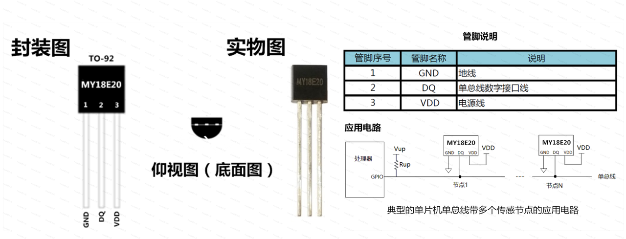
MY18E20 is a high-precision programmable digital 1-Wire temperature measurement chip:
Its temperature measurement range is -55°C to +125°C, with a maximum resolution of 0.015°C
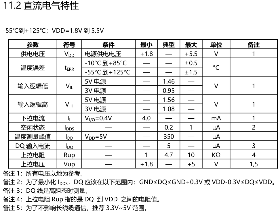
In the range of -10°C to +85°C, the maximum deviation is ±0.5°C; at extreme operating temperatures, the maximum error is less than ±1.5°C
The chip has a built-in 80-bit non-volatile storage unit for saving user-defined information, such as high/low temperature alarm thresholds, sensor node numbers, location information, temperature calibration information, etc.
Through one GPIO port, the microprocessor can read/write the chip's control registers according to the software commands of the 1-Wire protocol, configure settings such as temperature measurement accuracy and alarm thresholds, and periodically collect digital temperature information.
1. MY18E20 Sensor Communication Protocol Analysis
It should be noted that some terms about 1-Wire communication in the datasheet differ from the terms we use, but they refer to the same objects:
Host/device/controller: refers to the microcontroller that initiates communication on the 1-Wire bus.
Slave/chip/sensor: refers to the sensor that responds to communication on the 1-Wire bus.
Read time slot: refers to the communication process in which the host sends a read signal.
Write time slot: refers to the communication process in which the host sends a write signal.
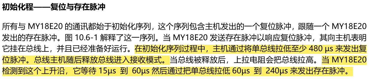
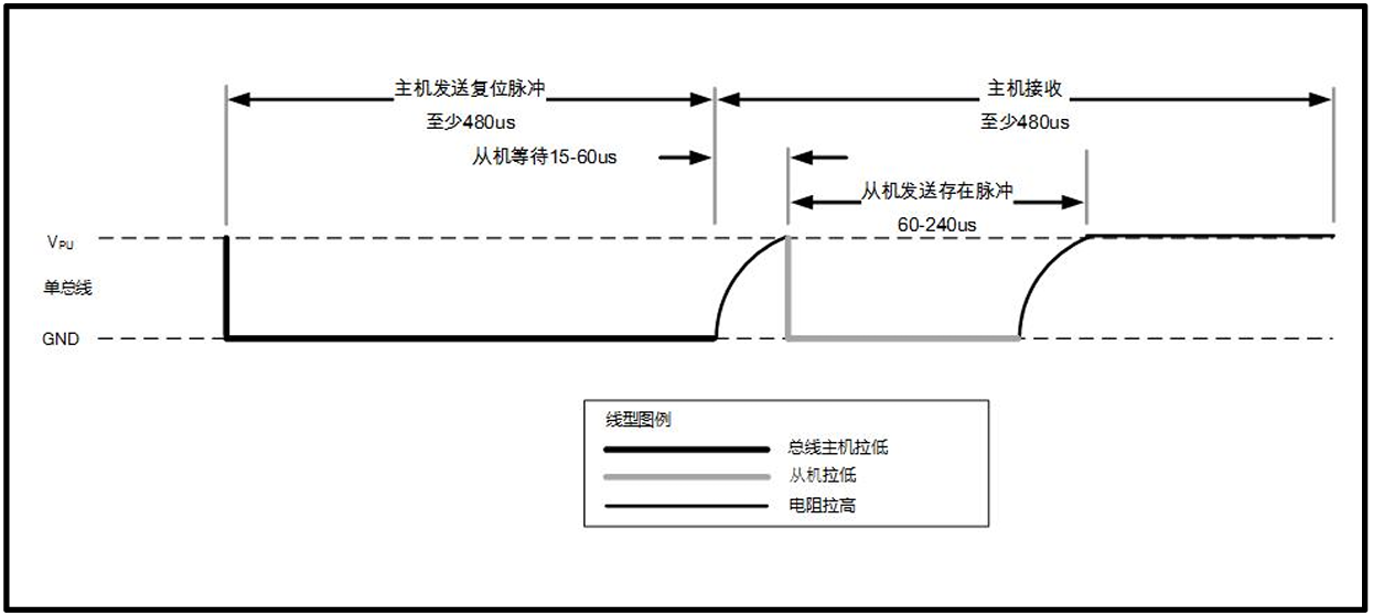
Reset signal/call signal: initiated by the host; after pulling the bus low for a certain time, the host releases it and waits for the slave to respond.
Presence signal/response signal: after the host sends the call signal, the slave detects the rising edge of the bus and pulls the bus low for a period of time.
1.1 Structure and Working Principle of the MY18E20 Sensor
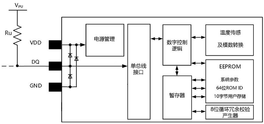
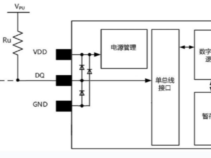
The MY18E20 sensor mainly consists of the following parts:
EEPROM: mainly stores system parameters, the 64-bit ROM ID, and 10 bytes of user storage. The 64-bit ROM stores the device's unique ID serial code. The microcontroller (host) identifies and addresses devices on the bus through each device's unique 64-bit code. Because each device has a unique code, the number of devices that can theoretically be connected to the bus and addressed is unlimited.
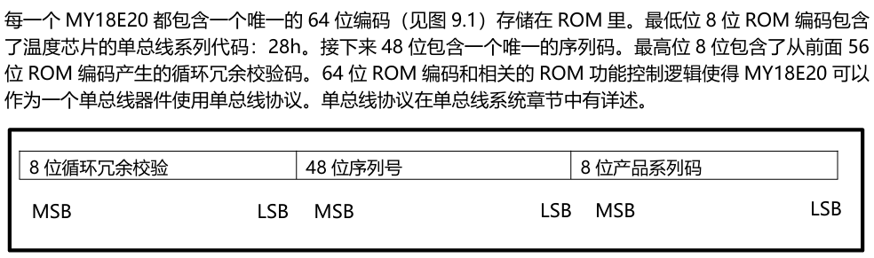
8-bit CRC generator: the cyclic redundancy check byte is part of the MY18E20's 64-bit ROM code, located in the 9th byte of the scratchpad. The ROM code CRC is calculated from the first 56 bits of the ROM code and stored in the most significant bits of the ROM. The scratchpad CRC is calculated inside the scratchpad, so it changes as the data in the scratchpad changes. The CRC provides the host with a data verification method when reading data from the scratchpad. To verify that the data was read correctly, the host must calculate it from the received data and compare this data with the CRC in the ROM (from the ROM read operation) or with the CRC in the scratchpad (from the scratchpad read operation). If the calculated CRC matches the read CRC, the data was received correctly.
Temperature sensor and ADC unit: performs temperature measurement and data conversion, and the resulting temperature data is stored in the temperature register of the scratchpad.
Digital control logic: performs corresponding operations according to the received ROM commands and function commands.
Scratchpad: the scratchpad contains a two-byte temperature register storing the digital output from the temperature sensor. In addition, the scratchpad provides two alarm trigger threshold registers, high (TH) and low (TL). The configuration register allows the user to set the resolution of the temperature digital conversion to 9, 10, 11, or 12 bits (corresponding to temperature resolutions of 0.5°C, 0.25°C, 0.125°C, 0.0625°C, with 12-bit resolution by default). Additional data space is provided for user use.
**Configuration-related data in the scratchpad can be stored in the non-volatile EEPROM. The data will not be lost when the chip loses power. On the next device power-up, the configuration-related data in the EEPROM will be automatically written to the scratchpad.**1-Wire interface: converts the command data received from the 1-Wire interface and sends it to the digital control logic unit.
Power management: converts and distributes the input voltage to each system for power supply.
The working steps of MY18E20 can be divided into three steps:
Initialize MY18E20: the MY18E20 chip initializes on power-up; the host sends a call signal, and the slave MY18E20 responds
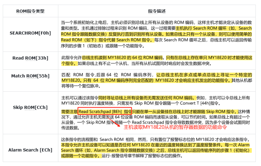
The host sends a ROM command (followed by any required data exchange): access each DS18B20, search the 64-bit serial number, read the matched serial number value, then match the corresponding DS18B20. If we only use a single DS18B20, we can skip the ROM command directly; the byte to skip the ROM command is 0xCC.
Here, "followed by any required data exchange" includes operations such as the host resetting the bus, sending function commands, and reading data.
Execute the MY18E20 function command (followed by any required data exchange): includes commands such as reading the temperature value, writing alarm trigger thresholds, and configuring temperature measurement accuracy
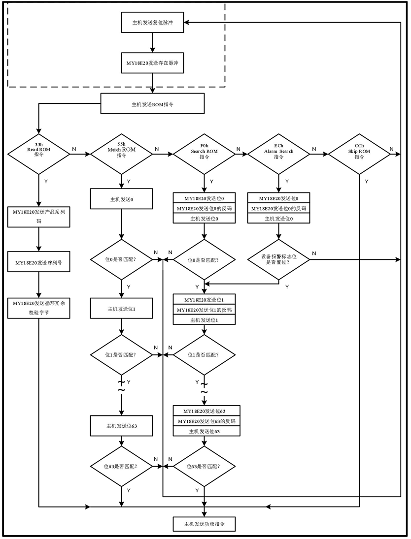
When the bus host detects the slave's response signal, it can send ROM commands. There are 5 ROM commands in total, each 8 bits long. Note that the host must send a ROM command before sending MY18E20 function commands:
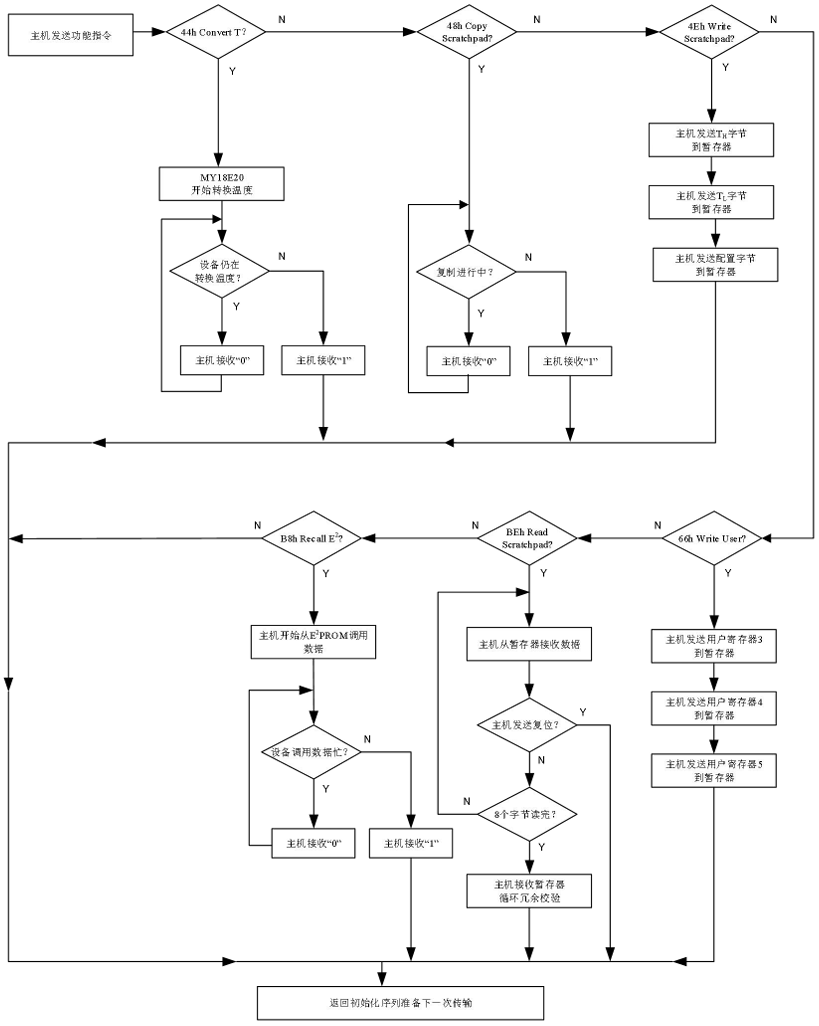
After the bus host uses a ROM command to address a MY18E20 with which it wishes to communicate, the host can issue one of the MY18E20 function commands. These commands allow the host to read/write data, including commands such as reading the temperature value, writing alarm trigger thresholds, and configuring temperature measurement accuracy.
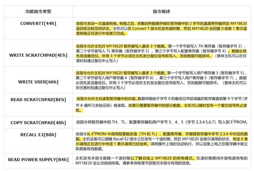
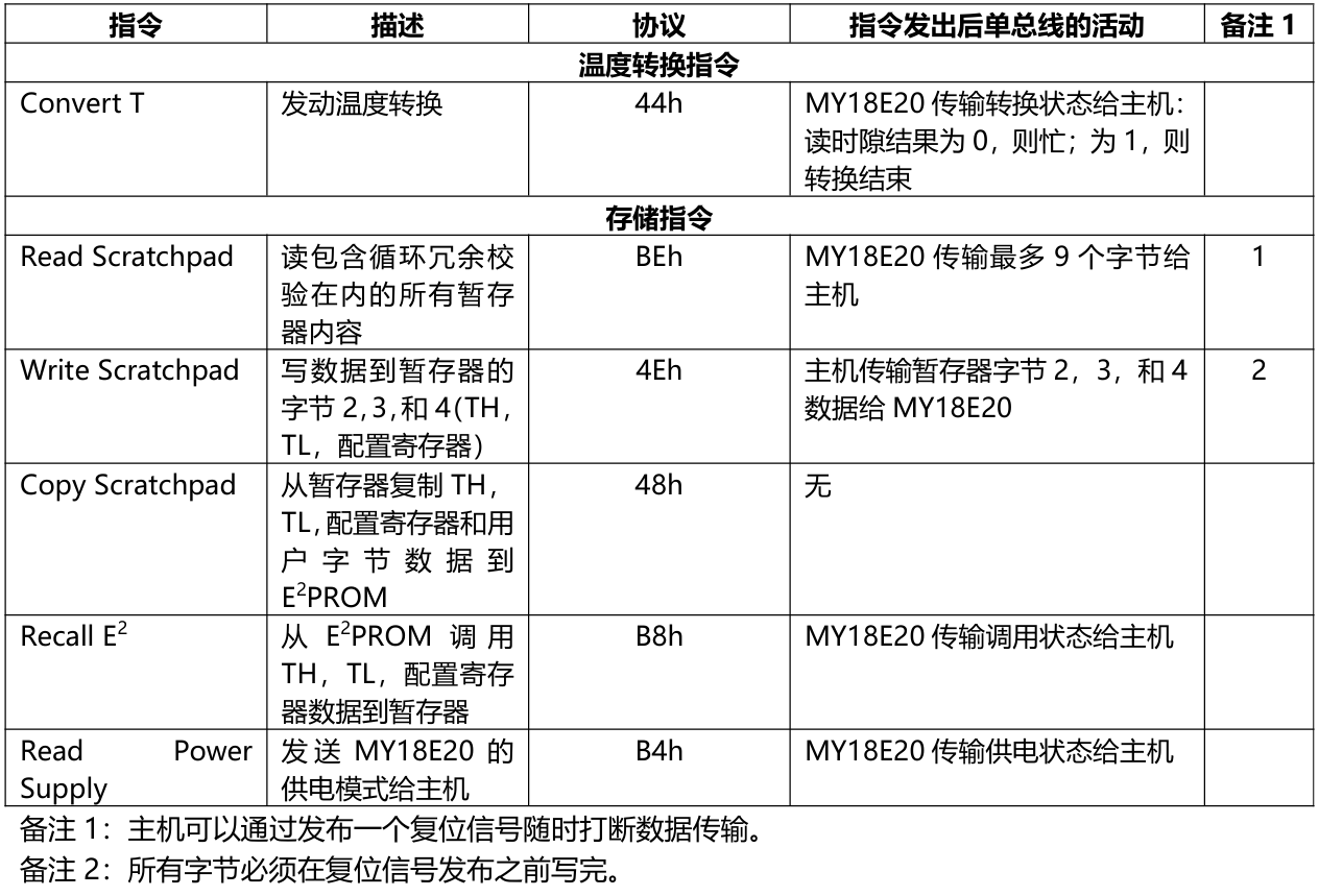
Here, the Copy Scratchpad[48h] command and Recall E2[B8h] command are mainly used in the following scenarios:
When we set the TH alarm threshold upper limit, TL alarm threshold lower limit, and temperature conversion accuracy in the scratchpad, we hope to save the configured data when the device shuts down or loses power, and read the last configuration data into the scratchpad after the next device power-up. At this time, to transfer the TH, TL, and configuration data from the scratchpad to the E2PROM, the host must issue the CopyScratchpad[48h] command. The data in the E2PROM registers is retained after power-off and is automatically loaded into the corresponding scratchpad positions at power-up. The data can also be reloaded at any time through the RecallE2[B8h] command. After the RecallE2[B8h] command, the host can send a read time slot; the chip will then return a status: 0 if the reload is still in progress, and 1 if it is complete.
The ROM command flow diagram is as follows:
The function command flow diagram is as follows:
1.2 MY18E20 Memory Organization
The MY18E20 memory includes an SRAM scratchpad and non-volatile E2PROM registers. The MY18E20 memory organization is shown in the following figure:
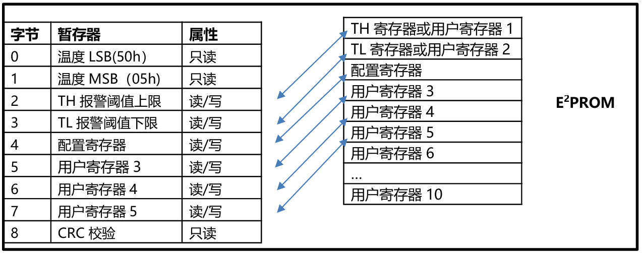
Among them:
Byte 0 and byte 1 are read-only: used to store the converted temperature data
Bytes 2 and 3 are used to access the TH and TL registers: store the high/low alarm temperature thresholds
Byte 4 contains configuration register data: used to configure the temperature conversion accuracy
Bytes 5, 6, and 7 can be read/written: provide data space for user use
Byte 8 is a read-only register: the CRC generated from bytes 0 to 7
Data can be written to bytes 2, 3, 4, 5, 6, and 7 through the WriteScratchpad[4Eh] and WriteUser [66h] commands. Data transmission must start from the least significant bit of byte 2 (i.e., the host sends data from LSB to MSB). To verify data integrity, the scratchpad can be read after the data write operation (through the Read Scratchpad [BEh] command). When reading the scratchpad, data transmission on the 1-Wire bus starts from the least significant bit of byte 0 (i.e., the slave sends data from LSB to MSB).
1.3 MY18E20 Sensor Application Circuit
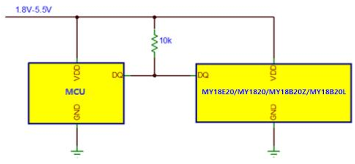
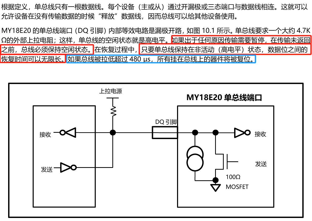
The MY18E20 is powered by an external power supply through the VDD pin, as shown in the following figure. The advantage of this mode is that no MOSFET pull-up is needed, and the 1-Wire bus can perform other operations arbitrarily during the temperature conversion process.

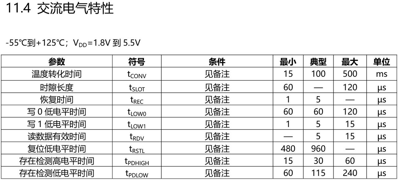
1.4 1-Wire Communication Timing and Electrical Characteristics
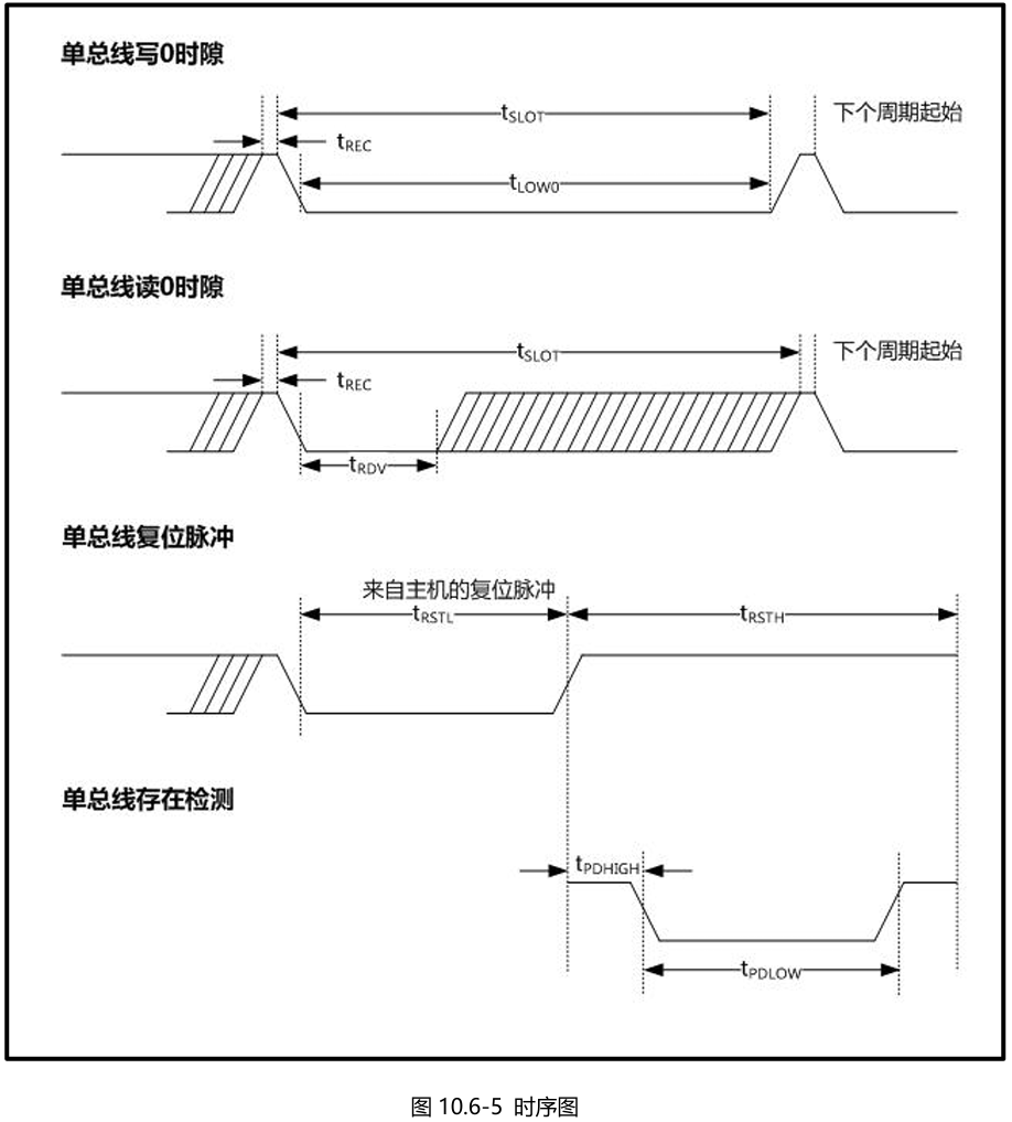
1.4.1 The Host Sends a Call Signal and the Slave Responds
1.4.2 The Host Reads/Writes Data Bits

1.5 Direct Temperature Measurement Function
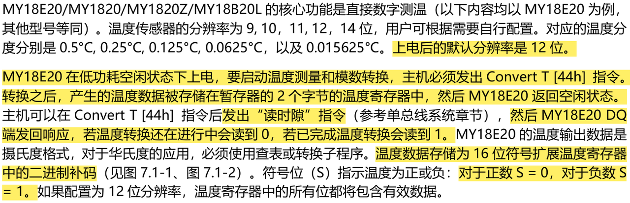
MY18E20 uses 16-bit two's complement format to store temperature data, and the temperature is in degrees Celsius. When the temperature conversion command is issued, the converted temperature value is stored in bytes 0 and 1 of the scratchpad in two-byte two's complement form.
The five S bits in the high byte are sign bits: when the temperature is positive, S=1; when the temperature is negative, S=0.
The remaining 11 bits are temperature data bits:
For 12-bit resolution: all bits are valid
For 11-bit resolution: bit 0 is undefined
For 10-bit resolution: bits 0 and 1 are undefined
For 9-bit resolution: bits 0, 1, and 2 are undefined
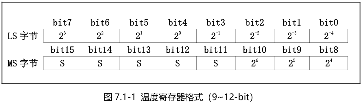
Note that the temperature is sent in big-endian order, i.e., the high-order MS byte comes first and the low-order LS byte comes last.

The temperature calculation method is as follows:
When the five sign bits S=0, the temperature is positive: directly convert the following 11-bit binary to decimal, then multiply by 0.0625 (12-bit resolution) to obtain the temperature value
When the five sign bits S=1, the temperature is negative: first convert the following 11-bit two's complement to the original code (the sign bit remains unchanged, the value bits are inverted and then 1 is added), then calculate the decimal value. Then multiply by 0.0625 (12-bit resolution) to obtain the temperature value
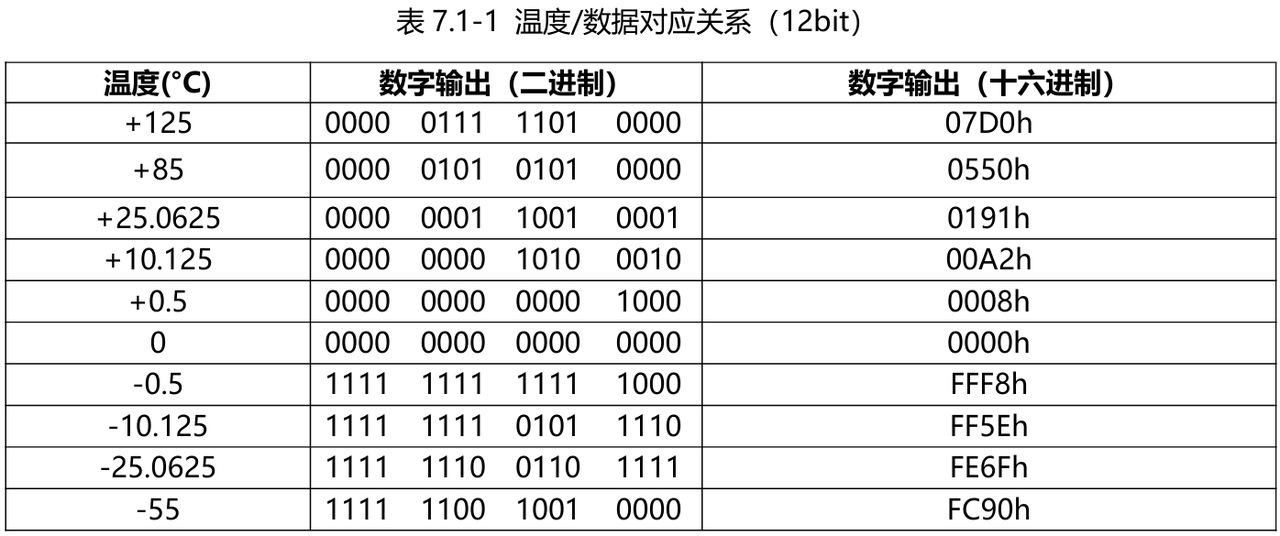
Using the above table as an example, explain the temperature calculation:
The digital output of +125℃ is 07D0 (00000111 11010000), which converted to decimal is 2000, corresponding to Celsius: 0.0625x2000=125°C
The digital output of -55℃ is FC90; first invert it, then add 1, and convert it to the original code: 11111011 01101111; the value bits converted to decimal are 870, corresponding to Celsius: -0.0625x870=-55°C
1.6 Temperature Acquisition Resolution Configuration
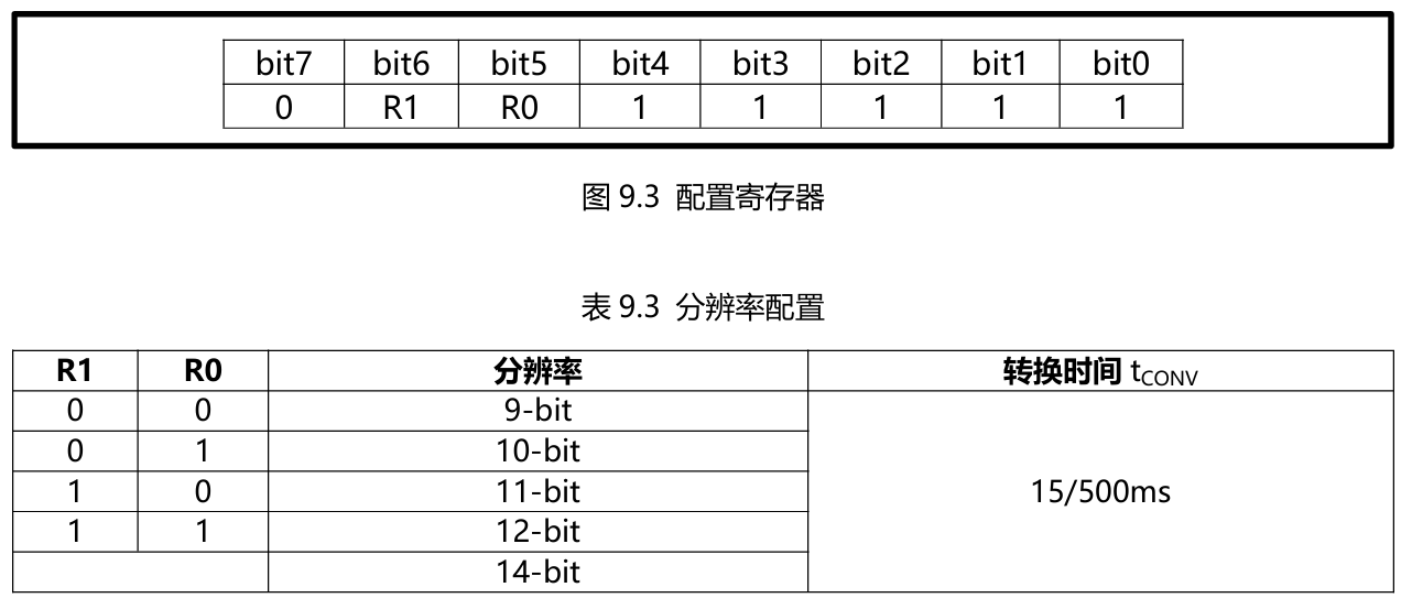
In the configuration register, we can set the ME18E20 conversion resolution through R0 and R1. After power-up, ME18E20 defaults to R0=1 and R1=1 (12-bit resolution). Bits 7 and bits 0 to 4 in the register are reserved for internal use by the device.
1.7 Alarm Function
After MY18E20 completes one temperature conversion, it compares the temperature value with the user-defined two's complement alarm trigger values stored in the TH and TL registers. The TH and TL registers are non-volatile (E2PROM), so the data is retained when the device loses power. TH and TL can be accessed through bytes 2 and 3 of the scratchpad.
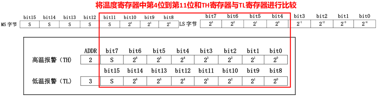
Since TH and TL are 8-bit registers, only bits 11 to 4 are used in the temperature comparison. If the measured temperature is less than or equal to TL or greater than or equal to TH, the alarm condition is met and a flag is set inside the chip. This flag is updated with each temperature measurement, so if the alarm condition is no longer met, the flag will be cleared after the next temperature conversion.
The host can check the flag status of all temperature chips on the bus by issuing an AlarmSearch[ECh] command. Any chip with the flag set will respond to this command, allowing the host to know which chip entered the alarm condition. If the alarm condition is met and the TH or TL setting is changed, another temperature conversion should be performed to verify the alarm condition.
1.8 CRC Generation
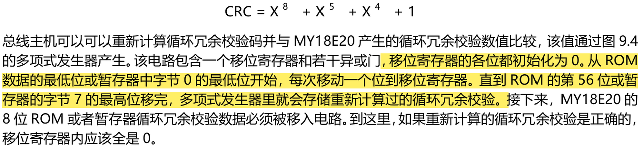
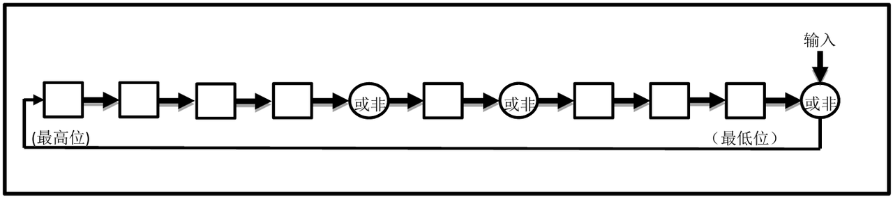
The CRC byte is part of the MY18E20's 64-bit ROM code, located in the 9th byte of the scratchpad. The ROM code CRC is calculated from the first 56 bits of the ROM code and stored in the most significant bits of the ROM. The scratchpad CRC is calculated inside the scratchpad, so it changes as the data in the scratchpad changes. The CRC provides the host with a data verification method when reading data from the scratchpad. To verify that the data was read correctly, the host must calculate it from the received data and compare this data with the CRC in the ROM (from the ROM read operation) or with the CRC in the scratchpad (from the scratchpad read operation). If the calculated CRC matches the read CRC, the data was received correctly. Whether to compare the CRC and continue operations depends entirely on the host. If the chip's CRC (ROM or scratchpad) does not match the value calculated by the bus host, no circuit inside the chip prevents further instruction execution.
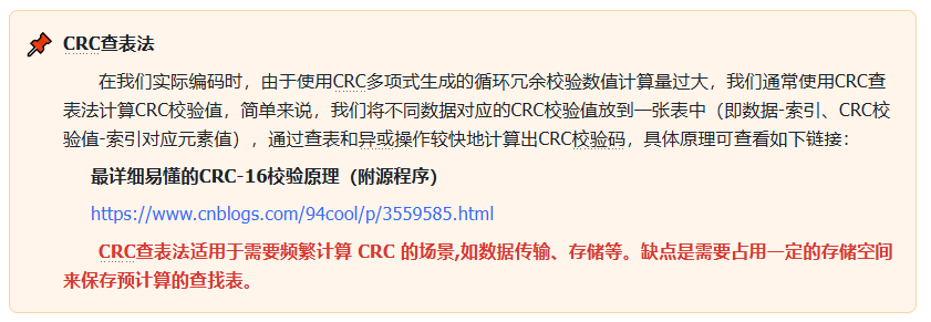
The CRC calculation method is as follows:
2. MY18E20 Sensor Driver Code
Here, since the MY18E20 sensor's working process is compatible with the DS18B20 sensor, we can directly use the DS18B20 sensor driver code. We first define a DS18X20 class (the DS18 series temperature sensors have many different models, and their communication processes are generally similar). The main functions of this class are as follows:
Initialize: when initializing the DS18X20 class, an instance of the OneWire class needs to be passed in; through composition, the DS18X20 class can use the methods of the OneWire class for 1-Wire communication.
Set power mode: supports two power modes, including independent power supply and parasitic power supply. In parasitic power supply mode, the sensor needs to be powered through the powerpin pin.
Scan sensors: scan all DS18X20 sensors on the 1-Wire bus and return their ROM address list.
Start temperature conversion: start the temperature conversion operation by sending the temperature conversion command CMD_CONVERT.
Read and write the scratchpad: read and write the sensor's scratchpad data, including configuration information such as temperature values and resolution.
Calculate and return the temperature value: read the sensor's temperature value, support the three units of Celsius, Fahrenheit, and Kelvin, and perform different temperature calculations according to the sensor model (DS18B20, DS18S20, etc.).
Set temperature resolution: set the resolution of temperature conversion, supporting settings between 9 bits and 12 bits.
Here, the DS18X20 class and the OneWire class use a composition relationship rather than an inheritance relationship:
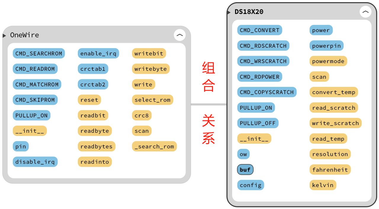
This is mainly based on the following considerations:
Single responsibility principle:
The OneWire class focuses on the low-level implementation of 1-Wire bus communication and provides a series of basic operations such as reading/writing data and resetting.
The DS18X20 class focuses on the upper-level logic for the DS18X20 temperature sensor, such as temperature conversion and temperature reading, and encapsulates the specific commands of the DS18X20 sensor (such as the temperature conversion command CMD_CONVERT and the read scratchpad command CMD_RDSCRATCH).
This design follows the single responsibility principle, giving the two classes a clear division of labor and responsibilities.
Reusability:
The OneWire class is a general-purpose 1-Wire communication class that can be reused by multiple device classes, such as other types of 1-Wire devices.
If inheritance were used, the DS18X20 class would be too coupled to the OneWire class, reducing the reusability of the OneWire class.
Flexibility:
In a composition relationship, the DS18X20 class can freely choose which OneWire class instance to use and configure it according to actual needs.
With inheritance, the DS18X20 class would have to inherit the OneWire class and could not freely choose which 1-Wire communication class to use.
Testability:
In a composition relationship, the DS18X20 class can be tested independently of the OneWire class, which helps improve test coverage and reliability.
With inheritance, tests of the DS18X20 class would be coupled to the implementation details of the OneWire class, reducing test independence.
Here, we first define the function command constants and initialization method used by the DS18X20 sensor:
# Define the DS18X20 temperature sensor class
class DS18X20:
"""
DS18X20 temperature sensor class, used to communicate with 1-Wire temperature sensors such as DS18B20 and DS18S20.
This class encapsulates the functions of the temperature sensor, including temperature conversion, temperature reading, resolution setting, etc.
Attributes:
ow (OneWire): an instance of the 1-Wire communication class.
buf (bytearray): buffer for storing scratchpad data (9 bytes).
config (bytearray): buffer for storing user configuration data (3 bytes).
power (int): power mode, 1 for independent power supply, 0 for parasitic power supply.
powerpin (machine.Pin): power pin object (used in parasitic power supply mode).
Methods:
powermode(powerpin: machine.Pin) -> int: set the power mode of DS18X20.
scan() -> list[bytearray]: scan DS18X20 sensors on the 1-Wire bus and return the ROM address list.
convert_temp(rom: bytearray) -> None: start sensor temperature conversion.
read_scratch(rom: bytearray) -> bytearray: read sensor scratchpad data.
write_scratch(rom: bytearray, buf: bytearray) -> None: write sensor scratchpad data.
read_temp(rom: bytearray) -> float: read sensor temperature.
resolution(rom: bytearray, bits: int) -> int: set or read the sensor temperature conversion resolution.
fahrenheit(celsius: float) -> float: convert Celsius to Fahrenheit.
kelvin(celsius: float) -> float: convert Celsius to Kelvin.
"""
# DS18X20 function commands
CMD_CONVERT = const(0x44) # Convert temperature command
CMD_RDSCRATCH = const(0xbe) # Read scratchpad command
CMD_WRSCRATCH = const(0x4e) # Write scratchpad command
CMD_RDPOWER = const(0xb4) # Read power command
CMD_COPYSCRATCH = const(0x48) # Copy scratchpad command
# Pull-up resistor control
PULLUP_ON = const(1)
PULLUP_OFF = const(0)
def __init__(self, onewire: OneWire) -> None:
"""
Initialize the DS18X20 class, passing in the 1-Wire communication class to use.
Args:
onewire (OneWire): an instance of the 1-Wire communication class.
"""
self.ow = onewire
# Store the 9 bytes of scratchpad data
self.buf = bytearray(9)
# Store the 3 bytes of user configuration data
self.config = bytearray(3)
# Independent power supply by default
self.power = 1
self.powerpin = NoneThen the method for setting the power mode of the DS18X20 temperature sensor is defined:
def powermode(self, powerpin: Pin = None) -> int:
"""
Set the power mode of DS18X20.
Args:
powerpin (machine.Pin): power pin object (used in parasitic power supply mode). If None, use the default mode.
Returns:
int: power mode, 1 for independent power supply, 0 for parasitic power supply.
"""
# If powerpin is already set, pull it low to turn off the pull-up resistor
if self.powerpin is not None:
self.powerpin(DS18X20.PULLUP_OFF)
# Send the CMD_SKIPROM command
self.ow.writebyte(OneWire.CMD_SKIPROM)
# Send the read power mode command
self.ow.writebyte(DS18X20.CMD_RDPOWER)
# Read the power mode
self.power = self.ow.readbit()
# After reading, set powerpin to push-pull output mode and pull it low
if powerpin is not None:
assert type(powerpin) is Pin, "powerpin must be a Pin object"
self.powerpin = powerpin
self.powerpin.init(mode=Pin.OUT, value=0)
# Return the power mode
return self.power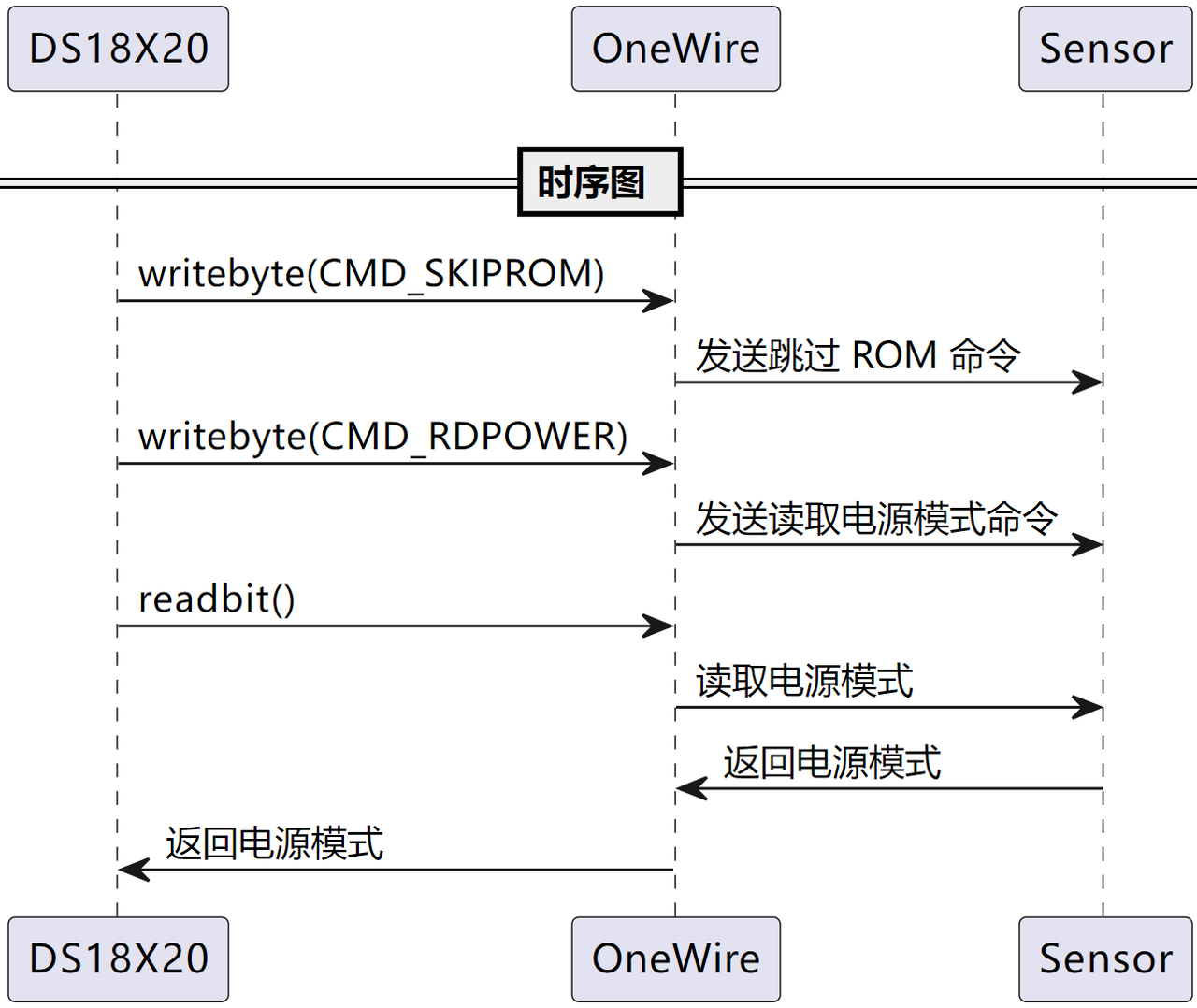
You can see that its main implementation relies on the OneWire instance to send and receive commands.
At the same time, the scan() method is defined to scan the DS18X20 temperature sensors connected to the 1-Wire bus and return their ROM address list. This list can be used in subsequent operations, such as reading temperature values or setting sensor parameters.
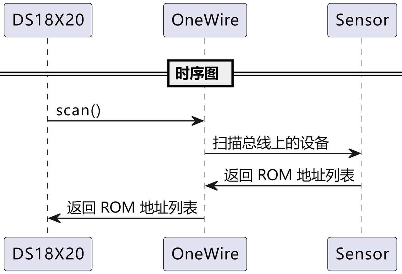
By checking the first few bytes of the ROM address, the DS18X20 series temperature sensors can be identified and distinguished from other devices that may be connected to the bus.
def scan(self) -> list[bytearray]:
"""
Scan DS18X20 sensors on the 1-Wire bus and return the ROM address list.
Args:
None
Returns:
list[bytearray]: sensor ROM list, each ROM is an 8-byte bytearray.
"""
if self.powerpin is not None:
self.powerpin(DS18X20.PULLUP_OFF)
# From the ROM list obtained by the 1-Wire scan, filter out the ROMs starting with 0x10, 0x22, or 0x28
return [rom for rom in self.ow.scan() if rom[0] in (0x10, 0x22, 0x28)]The core method of the DS18X20 class is the convert_temp() method, used to start the temperature conversion operation of the DS18X20 temperature sensor.
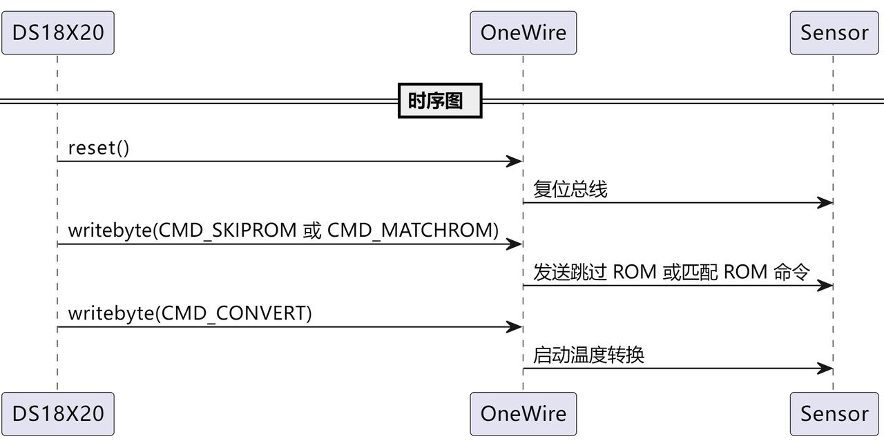
Note that calling this method only starts the temperature conversion operation and does not directly return the temperature value. To obtain the temperature value after the conversion is complete, call the read_temp() method.
def convert_temp(self, rom: bytearray = None) -> None:
"""
Start sensor temperature conversion.
Args:
rom (bytearray): the ROM address of the target temperature sensor. If None, broadcast to all sensors.
Returns:
None
"""
if self.powerpin is not None:
self.powerpin(DS18X20.PULLUP_OFF)
# The host resets the bus
self.ow.reset()
# When rom is not empty, send the CMD_SKIPROM command
# When there is only one temperature sensor on the bus, the CMD_SKIPROM command can be sent
if rom is None:
self.ow.writebyte(OneWire.CMD_SKIPROM)
else:
# Select the corresponding sensor according to the given ROM address
self.ow.select_rom(rom)
# Write the convert temperature command
self.ow.writebyte(DS18X20.CMD_CONVERT, self.powerpin)Its specific flow is shown in the following figure:
Then we define the methods for reading and writing the scratchpad. The scratchpad stores temperature data, user-defined data, and related configuration data (temperature conversion resolution, alarm high/low thresholds, etc.):
def read_scratch(self, rom: bytearray) -> bytearray:
"""
Read sensor scratchpad data.
Args:
rom (bytearray): the ROM address of the target temperature sensor.
Returns:
bytearray: scratchpad data (9 bytes).
Raises:
AssertionError: if the CRC check fails.
"""
if self.powerpin is not None:
self.powerpin(DS18X20.PULLUP_OFF)
# The host resets the bus
self.ow.reset()
# Select the corresponding sensor according to the given ROM address
self.ow.select_rom(rom)
# Write the CMD_RDSCRATCH command
self.ow.writebyte(DS18X20.CMD_RDSCRATCH)
# Read the scratchpad data and save it to buf
self.ow.readinto(self.buf)
# Perform CRC check
assert self.ow.crc8(self.buf) == 0, 'CRC error'
return self.buf
def write_scratch(self, rom: bytearray, buf: bytearray) -> None:
"""
Write sensor scratchpad data.
Args:
rom (bytearray): the ROM address of the target temperature sensor.
buf (bytearray): the data to write to the scratchpad (9 bytes).
Returns:
None
"""
if self.powerpin is not None:
self.powerpin(DS18X20.PULLUP_OFF)
# The host resets the bus
self.ow.reset()
# Select the corresponding sensor according to the given ROM address
self.ow.select_rom(rom)
# Write the CMD_WRSCRATCH command
self.ow.writebyte(DS18X20.CMD_WRSCRATCH)
# Write the scratchpad data
self.ow.write(buf)Note that before reading or writing scratchpad data, the 1-Wire bus is always reset first, and the corresponding sensor is selected according to the given ROM address:
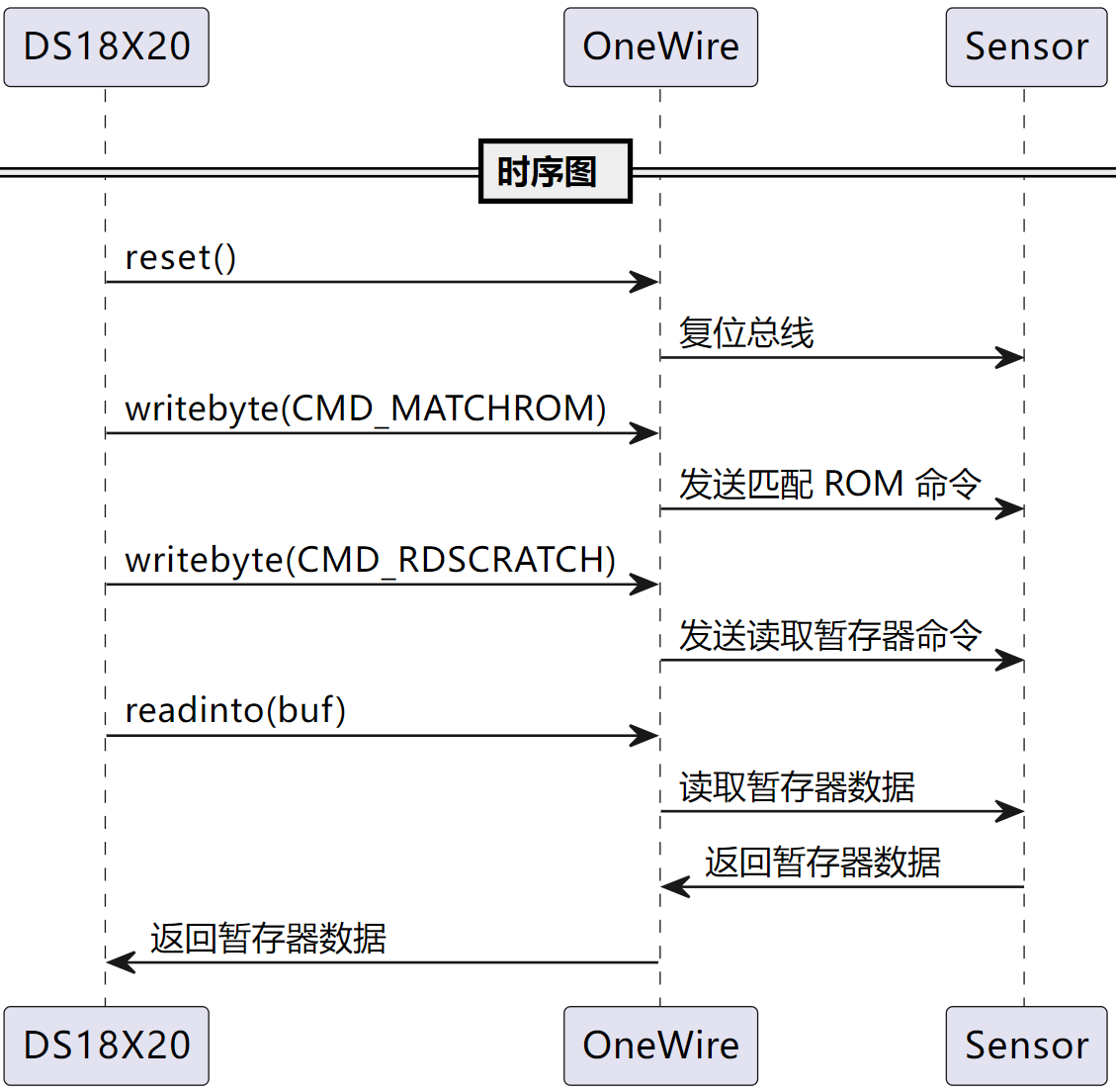
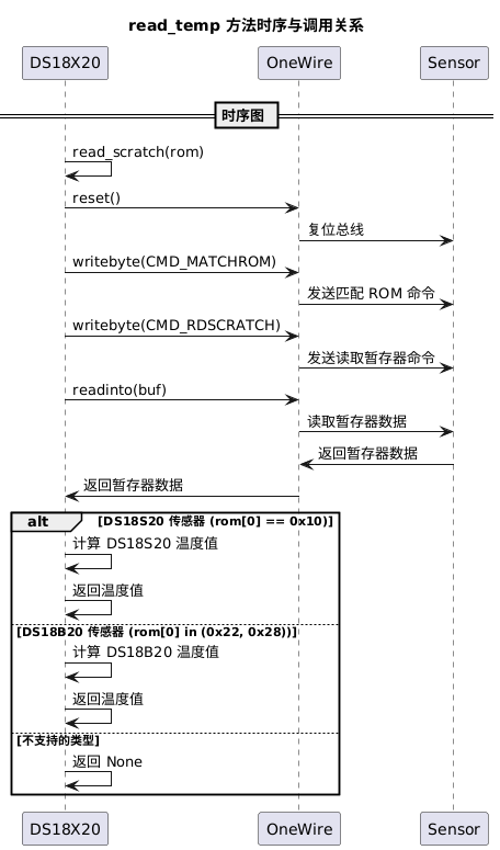
Then we define the read_temp() method for reading temperature data, mainly implemented by reading and writing the scratchpad. Note that this method also performs a CRC check to ensure that the read data is complete and reliable. If the CRC check fails, an AssertionError exception is thrown and None is returned.
def read_temp(self, rom: bytearray) -> float:
"""
Read sensor temperature.
Args:
rom (bytearray): the ROM address of the target temperature sensor.
Returns:
float: temperature value (Celsius). Returns None if the read fails.
"""
try:
# Read the scratchpad data
buf = self.read_scratch(rom)
# When the first byte of rom is 0x10, it is a different model of DS18x20 sensor
if rom[0] == 0x10:
# If the temperature is negative
if buf[1]:
t = buf[0] >> 1 | 0x80
t = -((~t + 1) & 0xff)
# If the temperature is positive
else:
t = buf[0] >> 1
# Calculate the temperature value, including the decimal part
return t - 0.25 + (buf[7] - buf[6]) / buf[7]
# When the first byte of rom is 0x22 or 0x28, it is a DS18B20 sensor
elif rom[0] in (0x22, 0x28):
# Read two bytes from the buffer and combine them into a 16-bit unsigned integer
t = buf[1] << 8 | buf[0]
# Check whether this integer is greater than 0x7fff; if so, convert it to a negative number
if t & 0x8000:
# First convert the following 11-bit two's complement to the original code (the sign bit remains unchanged, the value bits are inverted and then 1 is added), then calculate the decimal value
t = -((t ^ 0xffff) + 1)
# Divide by 16, i.e., multiply by the coefficient 0.0625
return t / 16
else:
return None
# Throw the assertion exception
except AssertionError:
return NoneHere, in temperature value decoding, the code distinguishes the data processing logic for different sensor models, so it can be applied to a variety of DS18X20 series sensors. The specific flow is shown in the following figure:
We also define the resolution() method for setting and reading the temperature conversion resolution. This method mainly implements the setting of the temperature conversion resolution by writing the updated configuration data to the sensor's scratchpad:
def resolution(self, rom: bytearray, bits: int = None) -> int:
"""
Set or read the sensor temperature conversion resolution.
Args:
rom (bytearray): the ROM address of the target temperature sensor.
bits (int): temperature conversion resolution (9~12 bits). If None, read the current resolution.
Returns:
int: the number of resolution bits set or read.
"""
if bits is not None and 9 <= bits <= 12:
# Set the resolution information to the value of the bits variable
# Bit 3 of self.config is used to set the resolution
self.config[2] = ((bits - 9) << 5) | 0x1f
self.write_scratch(rom, self.config)
return bits
else:
data = self.read_scratch(rom)
return ((data[4] >> 5) & 0x03) + 9The specific flow is shown in the following figure:
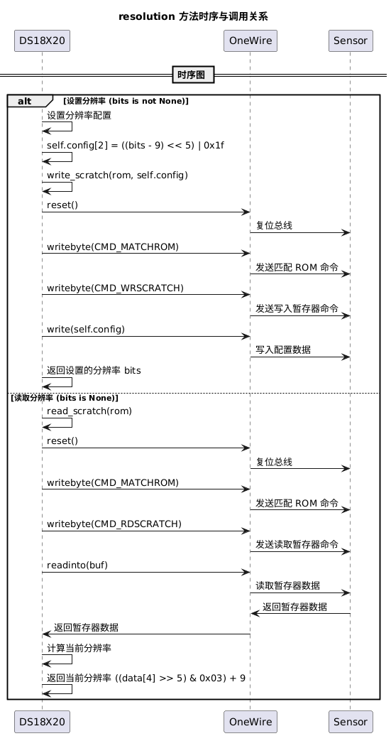
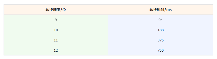
Note that the higher the resolution, the higher the precision of the temperature value, but the corresponding conversion time will also be longer. By adjusting the resolution, a trade-off can be made between precision and conversion speed to meet the needs of different application scenarios.
For the DS18 series sensors, the conversion precision and time are as follows:
Finally, we define the conversion methods for Celsius, Kelvin, and Fahrenheit. Among them, Celsius is the most widely used temperature unit, suitable for most daily life and industrial application scenarios. Fahrenheit is mainly limited to North America. Kelvin is mainly used in scientific research and some high-precision industrial applications. The relationship among the three is as follows:
The conversion formula between Kelvin and Celsius is: K = °C + 273.15
The conversion formula between Fahrenheit and Celsius is: °F = °C × 1.8 + 32
def fahrenheit(self, celsius: float) -> float:
    """
    Convert Celsius to Fahrenheit.

    Args:
        celsius (float): Celsius.

    Returns:
        float: Fahrenheit. Returns None if the input is None.
    """
    return celsius * 1.8 + 32 if celsius is not None else None

def kelvin(self, celsius: float) -> float:
    """
    Convert Celsius to Kelvin.

    Args:
        celsius (float): Celsius.

    Returns:
        float: Kelvin. Returns None if the input is None.
    """
    return celsius + 273.15 if celsius is not None else None
3. Application Experiment
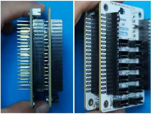
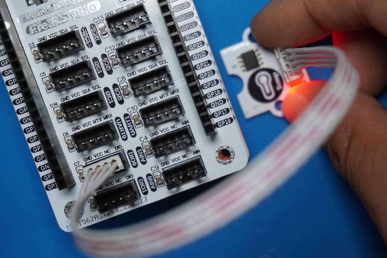
In the following experiment, we need to insert the Fengya One Board - Grove Interface expansion board into the Fengya One Board - Universal Compatible Expansion Board, and use a HY2.0-4P cable to connect the DIO0 interface on the Fengya One Board - Universal Compatible Expansion Board to the DIO0 digital interface on the GraftSense - DS18B20-based Temperature Sensor Module:
The pins used are shown in the following table:

The following code can be found in the elegance-devkit v1\Demo\38 OneWire_DS18B20 folder in our resource package.
In the software code, we import the related modules:
# Python env   : MicroPython v1.23.0
# -*- coding: utf-8 -*-
# @Time    : 2024/7/22 3:01 PM
# @Author  : Li Qingshui
# @File    : main.py
# @Description : DS18B20 temperature class experiment, using 1-Wire communication for data interaction

# ======================================== Import related modules ========================================

# Import hardware-related modules
from machine import Pin
# Import time-related modules
import time
# Import 1-Wire communication-related modules
from onewire import OneWire
# Import the temperature sensor class
from ds18x20 import DS18X20
In the initialization configuration, we define the 1-Wire communication pin ow_pin, create a DS18X20 object and bind it to ow_pin, for communicating with the DS18B20 sensor:
# ======================================== Global variables ============================================

# ======================================== Function definitions ============================================

# ======================================== Custom classes ============================================

# ======================================== Initialization configuration ==========================================

# Delay to wait for device initialization
time.sleep(3)
# Print debug information
print('FreakStudio : Using OneWire to read DS18B20 temperature')

# Define the 1-Wire communication pin
ow_pin = OneWire(Pin(14))
# Define the temperature sensor
ds18x20 = DS18X20(ow_pin)
In the main program, we perform the following operations:
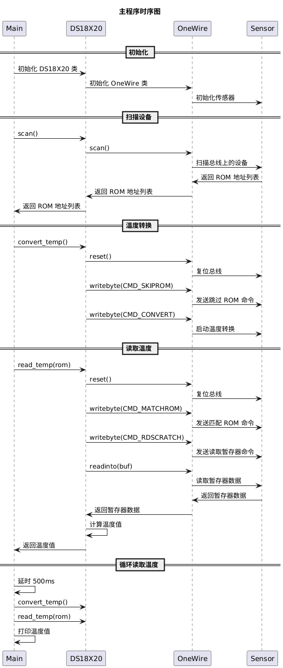
Preparation work:
Delay 3 seconds to ensure the system is stable;
Scan the DS18B20 sensor devices on the bus to obtain the device address list roms_list;
Print the ROM ID of the DS18B20 sensor devices;
Trigger all DS18B20 sensors to start temperature conversion;
Temperature reading loop:
Read the temperature every 500 ms;
Traverse each device address in roms_list;
Read the temperature value of the corresponding device and print it;
Trigger all DS18B20 sensors to start temperature conversion again;
The sample code is as follows:
# ======================================== Main program ===========================================

# Scan the DS18B20 devices on the bus to obtain the device address list
roms_list = ds18x20.scan()
# Print the device address list
for rom in roms_list:
    print('ds18b20 sensor devices rom id:', rom)
# Let all DS18B20 devices on the bus convert temperature
ds18x20.convert_temp()

# Loop to read temperature
while True:
    time.sleep_ms(500)
    for rom in roms_list:
        # Convert and print the temperature
        temp = ds18x20.read_temp(rom)
        # Print the temperature
        print('ds18b20 sensor {} devices temp {}'.format(rom, temp))
    # Start temperature conversion
    ds18x20.convert_temp()
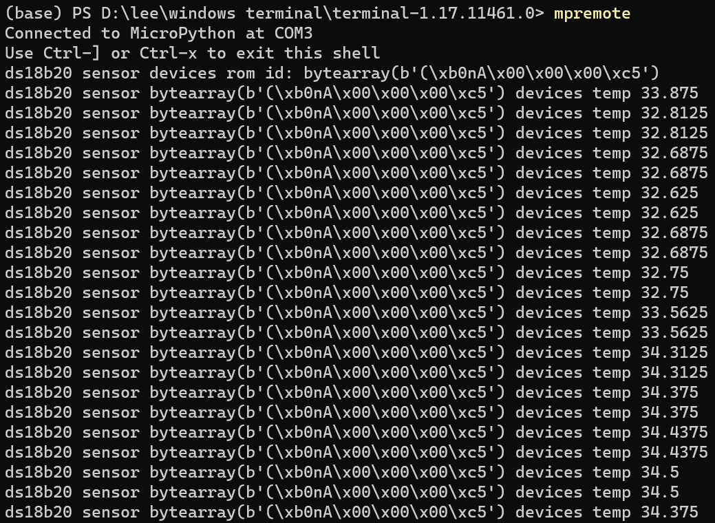
After flashing the code and connecting the terminal, gently pinch the sensor with your hand; you can see the terminal outputs the following: