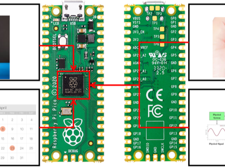
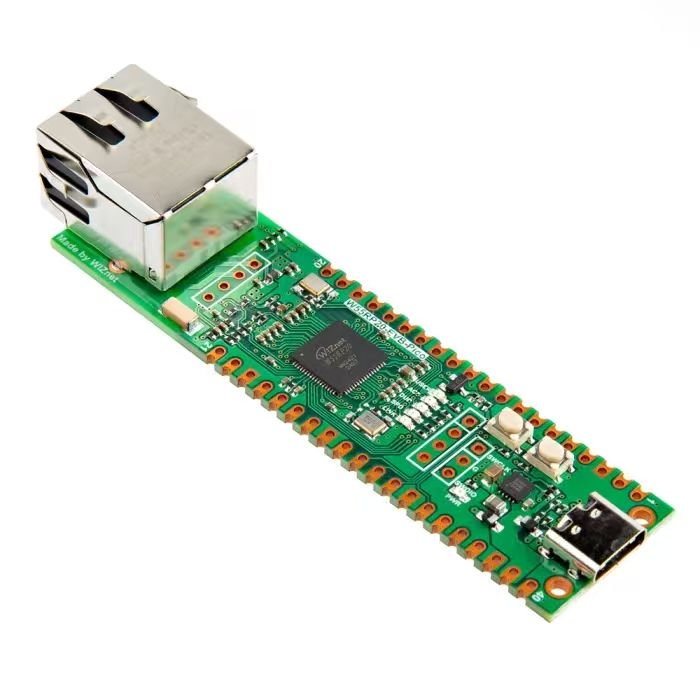
【Preliminary Note】The original hardware example in this article was written based on the RP2040. The actual hardware used in this hands-on demonstration features the W55RP20 as the main controller chip. The circuit logic and UF2 flashing operation principles are universally applicable, with only the main controller model differing. The original chip model mentioned in the circuit descriptions below is provided for reference purposes only.
Timer
1. Introduction to Timers
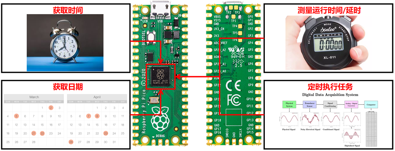
Imagine a scenario where we need to send data via the UART peripheral every 1 second, sample an external signal at equal intervals 100 times within 1 second via the ADC analog-to-digital converter, add a 10ms delay between executing two function functions, or obtain the current date and time. All these tasks that require tracking the passage of time and performing corresponding operations at set time points necessitate the use of the timer peripheral in the MCU.
You might say, "I can achieve the timing effect just through the following steps without using a timer". For example: assuming that the CPU takes 1 microsecond to execute the instructions inside a loop, we can set up a while loop, define a timing variable with an initial value of 0, and perform the following operations in the loop:
The timing variable is incremented;
Determine whether the timing variable reaches the preset time point;
If it is reached, execute the corresponding operation.
The main problem with this method is that it occupies all CPU resources to detect whether the preset time point is reached, making it impossible to perform other operations. Meanwhile, it is not flexible enough; for example, we may need to set multiple scheduled times to execute different operations or require custom time increments.
Simply put, a timer is a counter used for scheduled event processing: it increments or decrements at fixed intervals, and when it reaches a preset count value, it triggers a timer interrupt to execute the user's preset operation. Common timers can be categorized into the following types:
General-purpose timer: This is the most flexible timer, which can be used to measure the frequency/duration of external signals (e. g., detecting the duration of a key press) as well as to periodically execute repetitive tasks (e. g., reading sensor data once every second);
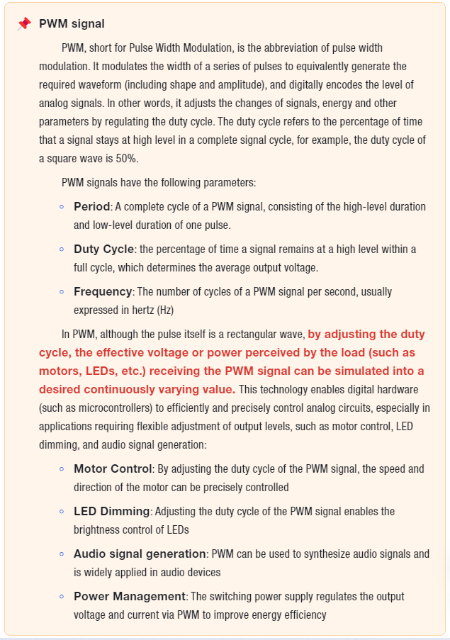
PWM Timer: A timer specifically designed to generate PWM (Pulse Width Modulation) signals, which can be used to control the power or position of a device; the most typical application scenario is the angle control of servo motors and steering gears.
Systick System Tick Timer: It is a built-in timer of the CPU core, serving as the "basic time reference" of the system. It is used to generate periodic interrupts, and is the core dependency for operating system task scheduling and system delay functions.
RTC Real-Time Clock: a timer specifically designed to record "real time/date". Different from other timers that only handle "interval timing", it supports direct configuration and reading of year/month/day/hour/minute/second, and is applicable to scenarios such as time logging, event timestamping, and alarm reminders.
WDT Watchdog Timer: A dedicated timer for system fault recovery, which continuously monitors the operating status of the CPU. If the CPU stops responding due to program runaway, the watchdog timer will trigger a system reset to restore the system to normal operation.
Here, the functions and applications of the RTC (Real-Time Clock) and WDT (Watchdog Timer) are relatively special compared with other timers, which will be covered in the subsequent chapters.
2. Working Principle of Timer
Here, we summarize the common features of different timers and explain their working principles.
2.1 Basic Composition of the Timer
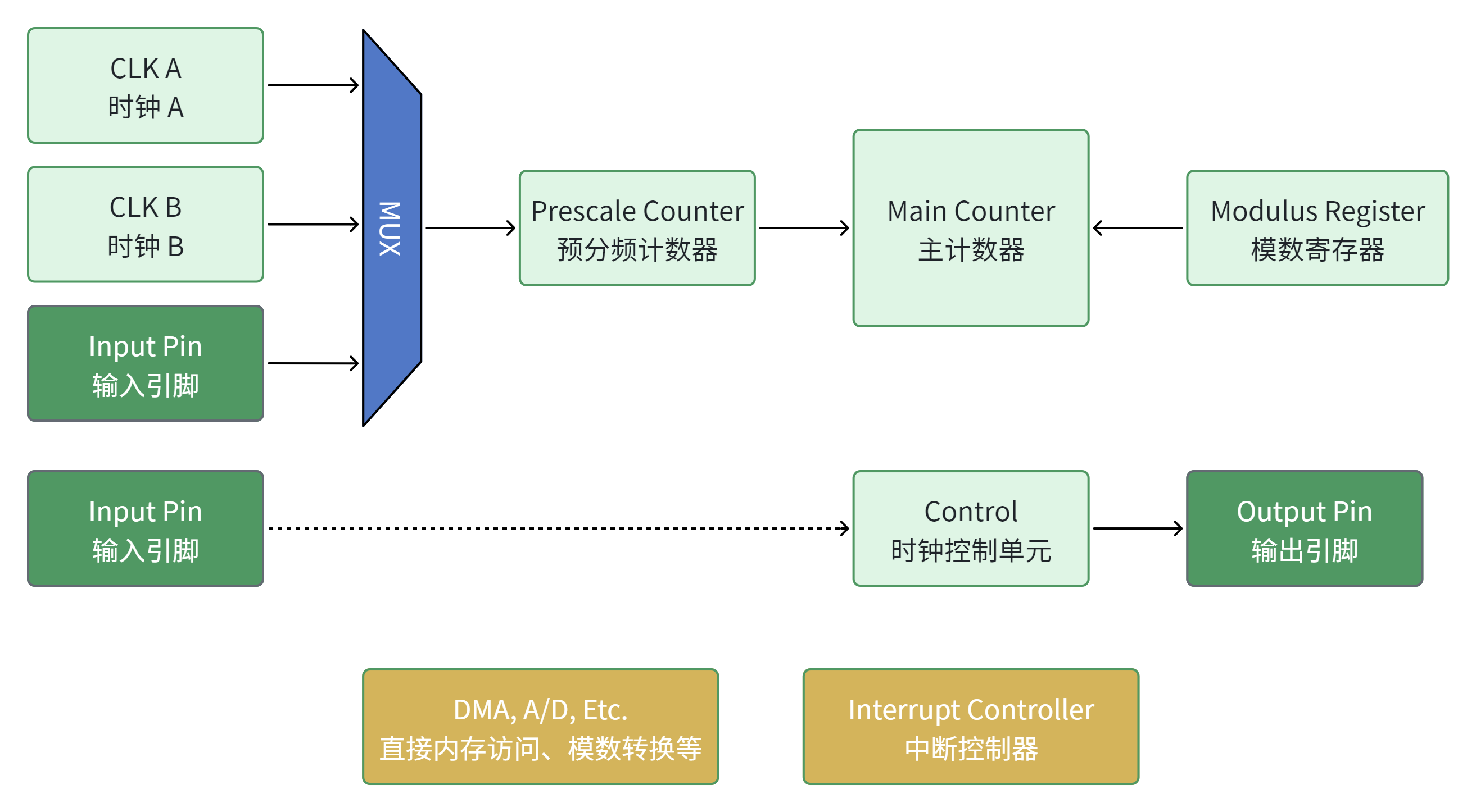
Figure 1-2 Basic composition diagram of the timer
Simply put, timers can be divided into the following parts:
Clock Input Unit: Each timer requires a clock source or time base. There are usually multiple possible clock sources, such as internal clocks and external signals, and one of them can be selected via a switch or a multiplexer to reuse;
Prescaler: To expand the counting range of the counter (the maximum count value of a counter has an upper limit; each pulse input to the clock will increment the counter's count by one unit, and when the input clock frequency decreases, the maximum counting duration of the counter will increase accordingly), the selected clock is fed into the "prescaler", which is primarily used to adjust the clock rate. The division factor of a prescaler is typically limited to a power of 2. For instance, values from 2⁰ to 2⁷ provide options of 1,2, 4,8, 16,32,64 or 128. Some prescalers can reach up to 2¹⁶, or 65536;
Counter: A register used to count clock pulses;
Clock Control Unit: it can be used to configure the operating mode of the timer (e. g., whether to count up or count down, whether to count on the rising edge or falling edge of the input clock, etc.), start-stop control, interrupt enable and other operations;
Related registers: mainly include comparison registers and count registers:
Count register: stores the current count value
Compare register: stores the value to be compared with the count register, and triggers a corresponding event when the value of the counter reaches the value of the compare register
Trigger Input Unit: Simply speaking, it refers to the signal introduced externally to this timer, which is capable of performing edge capture on the external input signal to generate a capture event, and can trigger an interrupt or DMA request while recording the value of the counter at the capture moment. Based on this principle, in conjunction with the real-time counting function of the counter, it can measure the pulse width of the captured signal, thereby realizing the measurement of the period or duty cycle of periodic waveforms, or being used for communication decoding.
Trigger Output Unit: When the value of the counter reaches the value of the comparison register, a trigger signal is output to other timers or peripherals.
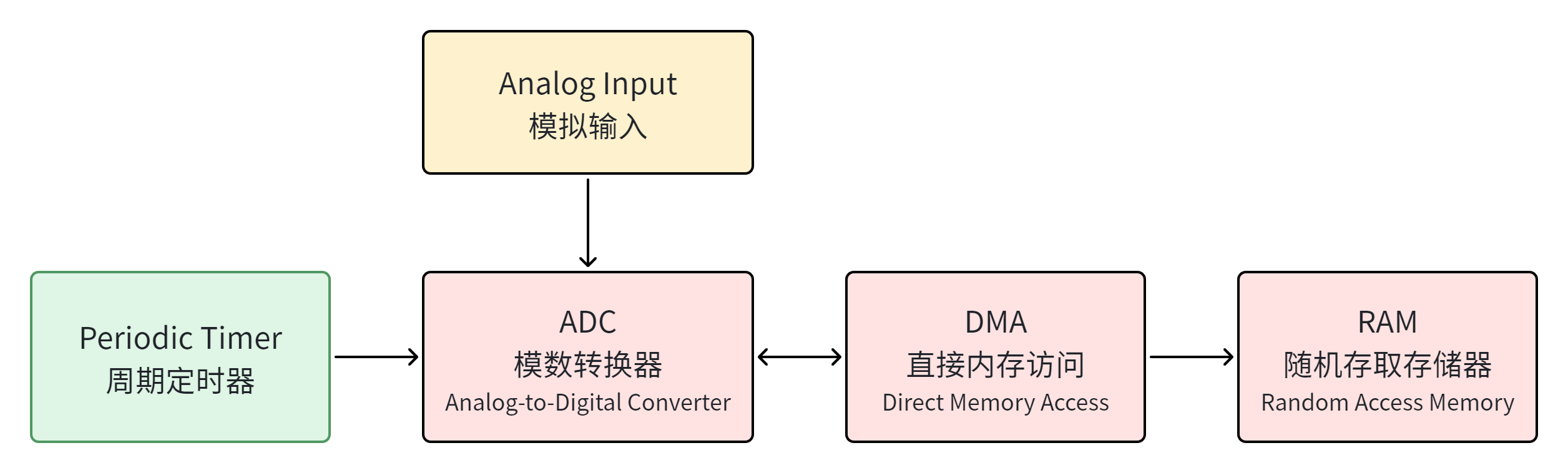
Connection Interrupts and DMA: When the timer count reaches the preset value, it can trigger an interrupt or DMA. A common application scenario is ADC timed sampling: we configure the timer period and the ADC's DMA, and when the timer reaches the set time, it triggers the DMA, which transfers the data collected by the ADC peripheral from the register to the memory unit.
Figure 1-3 ADC Timing Sampling and DMA Data Transmission Process
Common interrupt events include:
Counter Overflow Interrupt: Triggered when the counter rolls over from the maximum value to zero
Compare Match Interrupt: Triggered when the counter value equals the value of the compare register
2.2 Operating Modes of the Timer
Several common operating modes of timers include timing mode, counting mode and PWM mode.
2.2.1 Timing Mode
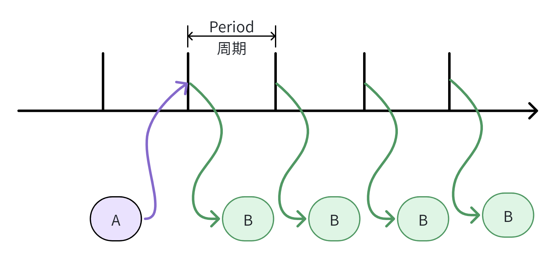
First of all, one point we need to clarify is that the main program and the timer task are executed asynchronously, and the execution flow of the timer task is independent of the main program flow.
The so-called timer mode means that the timer generates an interrupt after a set time interval, which is often used for the execution of periodic tasks.
Figure 1-4 Task Execution Timing in Timing Mode
Timer mode is commonly used in the following scenarios:
Timed Data Acquisition: Timed triggering of DMA to transfer the sensor data collected in the ADC registers to the memory
Task Scheduling: In a multitasking system, timers are used to schedule the execution of tasks to ensure that each task runs within the specified time interval.
Input Signal Detection: Detect whether there is signal input from keys, sensors, etc.
2.2.2 Counting Mode
In counting mode, the timer can be used to count the number of occurrences of external events, such as pulse counting, step counting for stepper motors, etc.
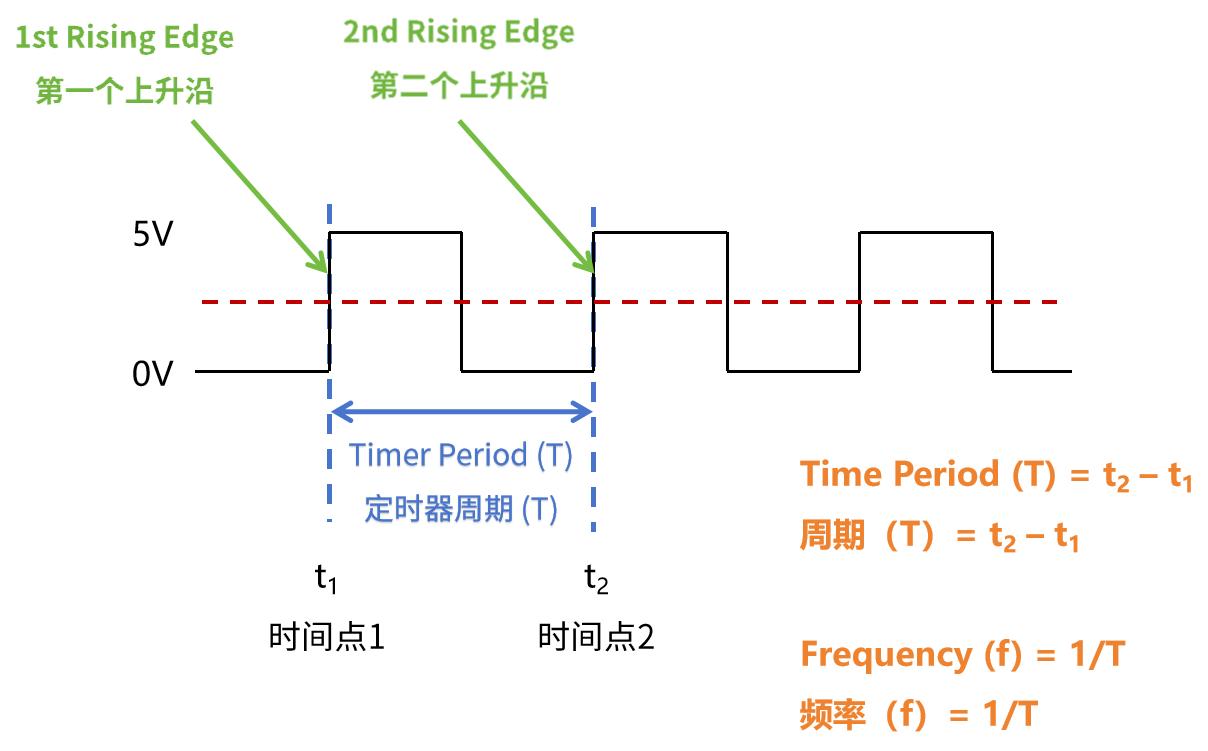
Schematic Diagram of Timer Period and Frequency Calculation (Figure 1-5)
2.2.3 PWM Mode
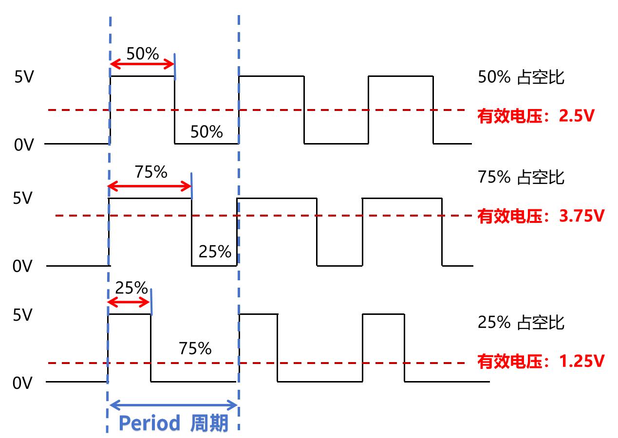
In PWM mode, the timer can generate PWM signals with specific frequency and duty cycle, which are used to control electronic devices, such as adjusting LED brightness and controlling the position of servo motors.
Schematic Diagram of PWM Signal Generation and Control (Figure 1-6)