



Illustrated Ethernet Protocol: 5‑4‑3 Rule, Segmentation, Micro‑Segmentation and VLAN
It explains 5‑4‑3 rule, segmentation, micro‑segmentation and VLAN basics.
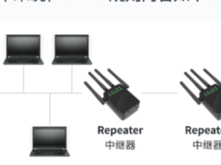
5‑4‑3 Rule
The 5‑4‑3 rule is a specification within Ethernet standards, applied to shared‑media Ethernet such as networks using coaxial cables or hubs. It defines topology constraints to guarantee valid signal transmission and collision detection.
Simply put, the contents of the 5‑4‑3 rule are as follows:
Analysis of Ethernet 5‑4‑3 rule, topology constraints and signal‑transmission guarantees for shared‑media networks
5 Segments Within one network, a maximum of 5 cable segments, also known as physical segments or collision domains, are allowed.
4 Repeaters Up to 4 repeaters, hubs or regenerators may connect these cable segments. These devices extend network coverage but also introduce signal latency.
3 Populated Segments Among the 5 cable segments, only up to 3 segments can attach end‑nodes such as computers and printers. The remaining 2 segments serve purely for signal extension, namely repeater segments.
Ethernet relies on the CSMA/CD protocol (Carrier‑Sense Multiple Access with Collision Detection) to handle network collisions. The 5‑4‑3 rule ensures signal‑propagation time stays within defined limits inside a collision domain for effective collision detection and processing. Meanwhile, limiting the count of repeaters and cable segments reduces signal attenuation and delay, preserving signal integrity and reliability across the network.
Nevertheless, with the widespread adoption of full‑duplex Ethernet and switches, the 5‑4‑3 rule is no longer valid for modern Ethernet networks. Switches eliminate collision domains; each port forms an independent collision domain and supports full‑duplex communication. Network design becomes far more flexible without constraints from the legacy 5‑4‑3 rule.
- Segmentation and Micro‑Segmentation
Legacy Ethernet networks consist of a single segment. All stations connected to the network receive transmitted data frames. As more stations join the network, collision frequency rises accordingly. To avoid performance degradation, networks can be segmented by deploying switches.
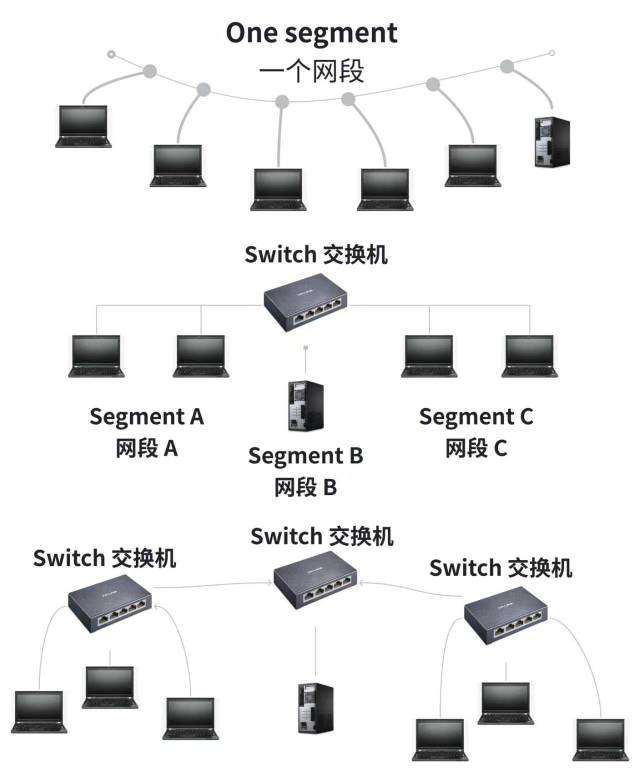
Performance‑optimization mechanism from single‑segment network to multi‑segment division via switches
Segmentation means dividing one large network into multiple smaller sub‑networks or zones. Micro‑segmentation is an advanced form of network segmentation, aiming for fine‑grained segmentation for every device, application or workload inside the network.
- VLAN Virtual Local Area Network
VLAN (Virtual Local Area Network) is a network technology that creates logically‑separated sub‑networks on top of a single physical network.
VLAN technology analysis: logical segmentation and broadcast‑domain‑isolation mechanism for physical networks
Bridging devices normally forward broadcast traffic to all attached network segments. This may trigger broadcast storms, especially inside large‑scale networks where broadcast packets circulate repeatedly and degrade network performance. VLAN tags data‑link‑layer frames. Devices belonging to different VLANs will not receive broadcasts from other VLANs even when physically interconnected. This improves security, prevents broadcast storms and enhances network flexibility and manageability.
Although VLAN splits large networks into smaller broadcast domains, traditional bridging still maintains MAC‑address tables for each VLAN, which may increase resource consumption and management complexity. In addition, legacy bridging devices cannot implement sophisticated access‑control policies across VLAN boundaries.