


I2C Bus Fundamentals (Part 1): Concepts, History & Daisy‑Chain Topology
I2C bus basics: 2‑wire SDA/SCL, address‑based multi‑device connection, version evolution from Philips to NXP
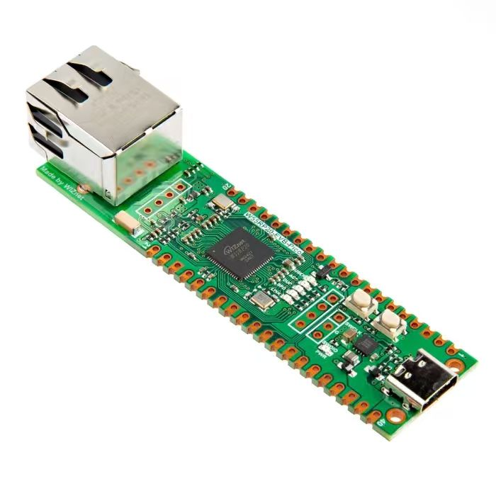
【Preliminary Note】The original hardware example in this article was written based on the RP2040. The actual hardware used in this hands-on demonstration features the W55RP20 as the main controller chip. The circuit logic and UF2 flashing operation principles are universally applicable, with only the main controller model differing. The original chip model mentioned in the circuit descriptions below is provided for reference purposes only.
1. Introduction to the I2C Bus
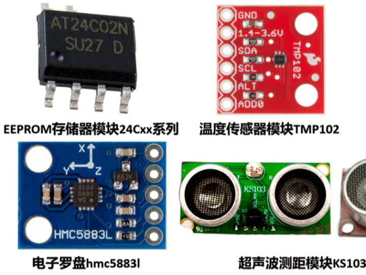
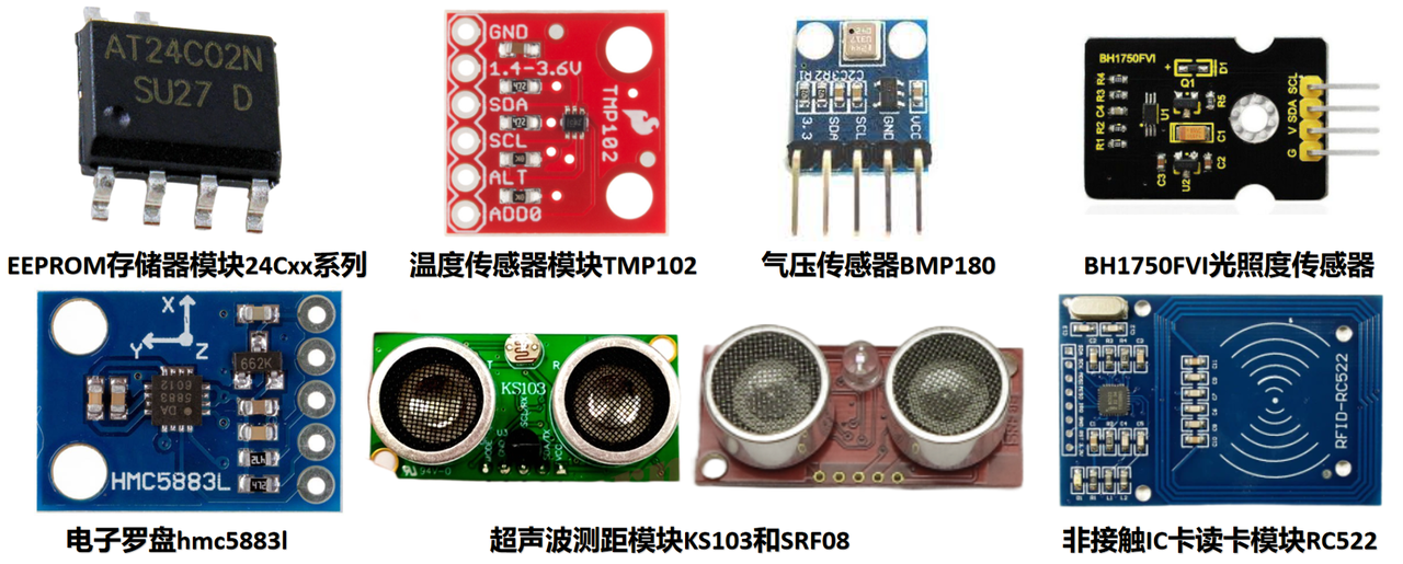
All of the sensor modules below communicate with a microcontroller using the I2C protocol.
The I2C bus has only two signal lines: the bidirectional serial data line, SDA, and the bidirectional serial clock line, SCL. Both SDA and SCL are bidirectional. The data lines of all devices on the I2C bus connect to SDA, while their clock lines connect to SCL.
Under the I2C bus protocol, communication nodes connected to the bus, such as sensors or microcontrollers, are typically identified by 7-bit addresses, which function much like identification numbers. During communication, each node may act either as a controller that initiates communication or as a target that passively responds when addressed by a controller. One controller can communicate with multiple targets, and multiple controllers can also share a bus with multiple targets.
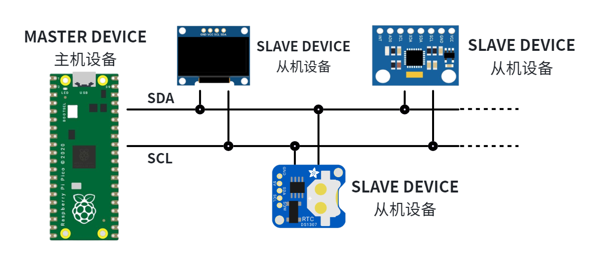
A connection example diagram of one host communicating with multiple slave devices
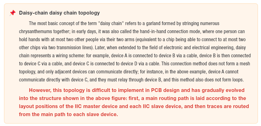
Multiple devices can be connected to the same SDA and SCL lines in a “daisy-chain” configuration. Because each device on the bus has a different address, the controller can select the specific device with which it wants to communicate. 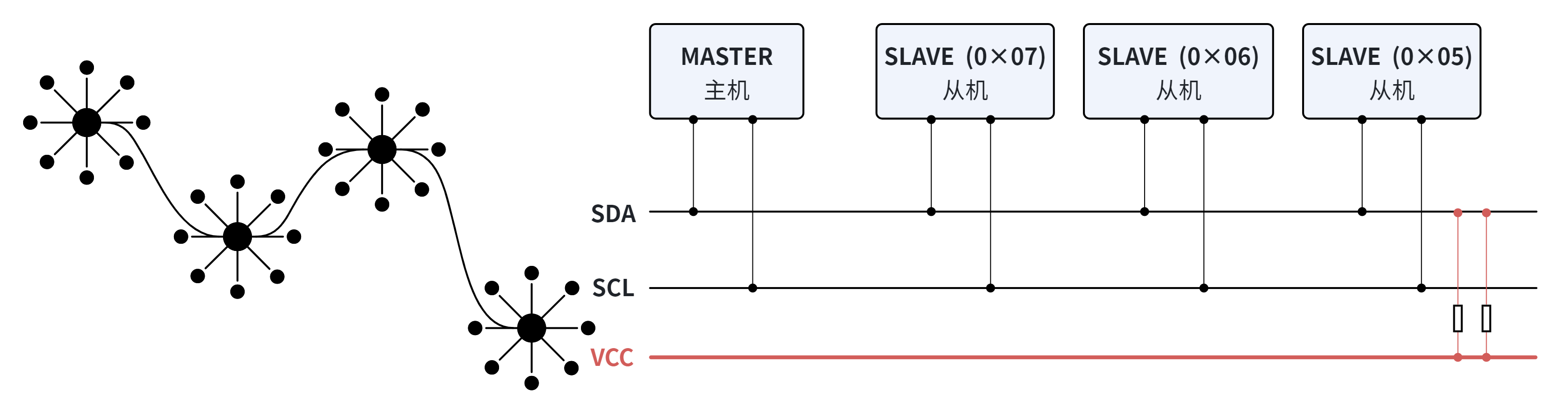
2. History of the I2C Bus
The original I2C bus specification was developed by Philips Semiconductors in 1982. It was widely used for short-distance, on-board communication between processors or microcontrollers and low-speed peripheral integrated circuits. The original specification supported communication at only 100 kHz and provided only 7-bit addressing, limiting the bus to 112 devices because several addresses were reserved and could never be used as valid I2C addresses.
After inventing the I2C bus, Philips used the technology to develop numerous chips with built-in I2C functionality. Some of these chips were used in Philips products, while others were sold to third-party chip users. Philips also licensed its patented I2C bus technology to other semiconductor manufacturers, which integrated it into their own chips to add I2C functionality. Since the mid-1990s, many competitors—including Siemens, NEC, Texas Instruments, STMicroelectronics, and Motorola—have introduced compatible I2C products.
Whether selling I2C bus chips or licensing its patented I2C bus technology, Philips also provided a complete set of technical documentation and application guidelines. This established a unified standard for devices with I2C functionality: the I2C bus specification. In 2016, Philips' semiconductor division became an independent company named NXP. NXP is now the steward of the I2C bus specification.
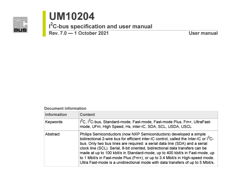
The current I2C bus specification is available at the following link:
https://www.nxp.com/docs/en/user-guide/UM10204.pdf
The original I2C patents expired on October 10, 2006. As a result, the I2C bus can now be used freely without patent royalties, although manufacturers must still pay to obtain an I2C target address allocated by NXP. NXP participated in and contributed to the MIPI I3C specification introduced by the MIPI Alliance in 2017. MIPI I3C provides backward compatibility with I2C, higher speeds, lower power consumption, and a royalty-free version.
The revision history of the I2C bus specification is shown in the table below:
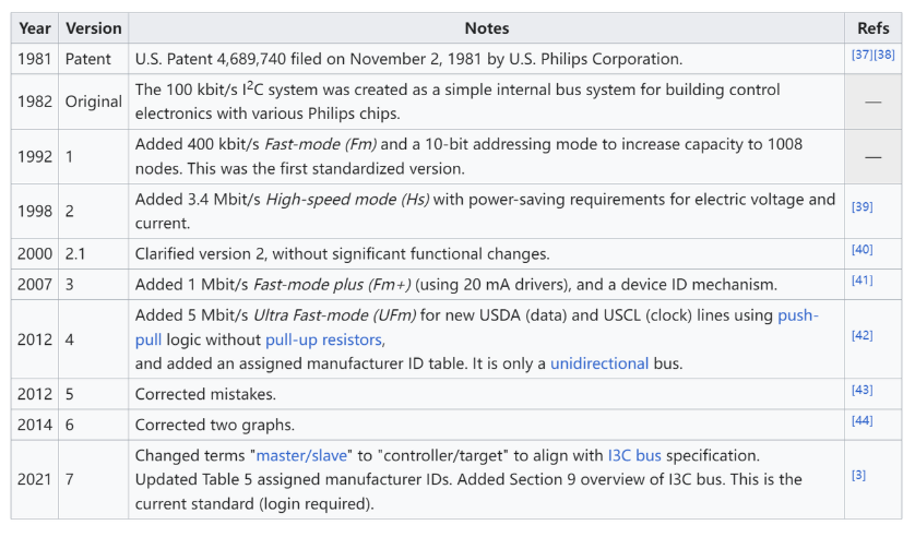
Several important changes are summarized below:
Initial release: Originally introduced by Philips in 1982.
V1.0—1992: Removed content concerning software-programmable target addresses and the detailed description of Low-speed mode. Added Fast-mode, with a bit rate of up to 400 Kbit/s, while maintaining backward compatibility with the 0–100 Kbit/s bit rate of Standard-mode.
V2.0—1998: By this time, the I2C bus had become a worldwide standard, licensed to more than 50 companies and implemented in over 1,000 different ICs. This revision added High-speed mode, with a bit rate of up to 3.4 Mbit/s and backward compatibility with Fast-mode and Standard-mode. It also added support for low-voltage devices operating at 2 V or below while retaining compatibility with higher-voltage devices; removed the 0.6 V/6 mA requirement for Fast-mode output stages; introduced bus-voltage-dependent levels for new devices in place of fixed levels; and added guidance on using bidirectional level shifters.
V2.1—2000: Allowed the SCL high period to be extended following a repeated START condition in High-speed mode and relaxed several timing requirements for High-speed mode.
V3.0—2007-06-19: Added Fast-mode Plus, which increased drive strength tenfold and raised the bit rate from Fast-mode's 400 Kbit/s to 1 Mbit/s to support longer buses and/or higher-speed applications.
V4.0—2012-02-13: Added the unidirectional I2C bus and Ultra Fast-mode, with a bit rate of up to 5 Mbit/s.
V6.0—2014: Revised the method used to calculate pull-up resistor values.
V7.0—2021: Updated the list of I2C manufacturer IDs; replaced the terms “master/slave” with “controller/target”; and added information about the MIPI I3C specification. With bit rates of up to 10 Mbit/s, I3C provides a flexible upgrade path from I2C and SPI.
All of the sensor modules below communicate with a microcontroller using the I2C protocol.