



Full Analysis of SPI Emulation Using Raspberry Pi Pico PIO: Principles, Timing and Code Practice
This article introduces CPOL=0/CPHA=0 SPI realized by RP2040 PIO in MicroPython, including PIO assembly code, PIOSPI class with read/write functions, loopback t
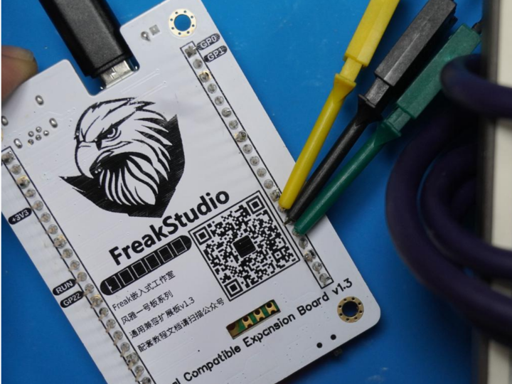
Here, we need to use the KingST logic analyzer to connect to the long-pin headers on the Fengya One Board - Universal Compatible Expansion Board:
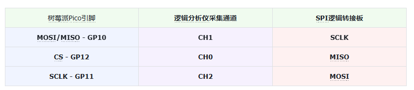
The pins used by the Raspberry Pi Pico are shown in the following table:
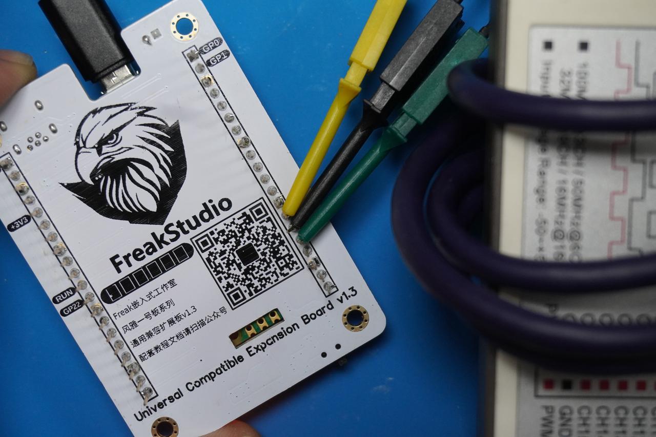
The overall physical connection is shown below:
1. Using PIO to Implement the SPI Communication Protocol
Here, we take SPI communication with both CPOL clock polarity and CPHA clock phase equal to 0 as an example to explain how to use PIO to implement the SPI communication protocol. First, let's recall the basic points of SPI communication. When CPOL = 0 and CPHA = 0, the clock signal remains low when no data is being transmitted, and data is sampled on the rising edge of the clock signal (i.e., when data is sent to the receiving device, the clock signal transitions from low to high):
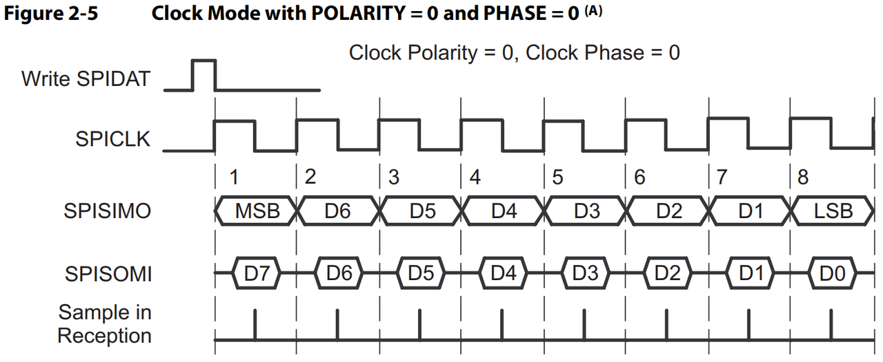
The communication flow can be simplified as:
When no data is being transmitted, SCLK (the clock line) remains low.
In each clock cycle, data is transmitted on the MOSI (Master Output Slave Input) or MISO (Master Input Slave Output) line. The data signal changes on the falling edge and is read on the rising edge.
Data transmission is synchronized by the clock; each time one data bit is transmitted, the clock changes once.
Here, we refer to the official example and modify it as follows:
# Python env : MicroPython v1.23.0
# -*- coding: utf-8 -*-
# @Time : 2024/11/6 4:26 PM
# @Author : Li Qingshui
# @File : pio_spi.py
# @Description : PIO experiment: implement SPI protocol communication in a PIO program
# Reference code: https://github.com/raspberrypi/pico-micropython-examples/blob/master/pio/pio_spi.py
# ======================================== Import related modules ========================================
# Import hardware-related modules
from machine import Pin
# Import RP2040-related modules
from rp2 import PIO, StateMachine, asm_pio
# ======================================== Global variables ============================================
# ======================================== Function definitions ============================================
# Use the @asm_pio decorator to define a PIO program
# The OSR shift register shifts left, with autopull and autoload enabled, and a shift count threshold of 8
# The two pins used for sideset operations are initialized to low and high level respectively, and the pin used for output is initialized to low level
(out_shiftdir=0, autopull=True, pull_thresh=8,
autopush=True, push_thresh=8,
sideset_init=(PIO.OUT_LOW, PIO.OUT_HIGH), out_init=PIO.OUT_LOW)
def spi_cpha0() -> None:
"""
PIO implementation of the SPI protocol (CPHA=0\CPOL=0)
This PIO program implements the CPHA=0\CPOL=0 mode of the SPI protocol and supports 8-bit data transmission.
It controls SCK and MOSI through the sideset pins while reading MISO data.
Args:
None
Returns:
None
"""
# Set register x to 6; register x is used to count down the number of bits per byte
# Setting it to 6 means 7 clock cycles are needed; x decrements from 6 to 0
set(x, 6)
# Used to define the start position of the loop
wrap_target()
# When the OSR output shift counter reaches its threshold (i.e., 8 data bits), take one byte of data from the TX FIFO queue into the output shift register
# If the TX FIFO is empty, wait until data is filled
# Set the sideset clock line SCK to high; [1] means wait one cycle
pull(ifempty) .side(0x2) [1]
# Define the label bitloop, used for the bit loop of one byte of data (sending and receiving each bit)
label("bitloop")
# Take 1 bit from the output shift register OUT and output it through pins, i.e., output the data to the MOSI pin
# Set SCK low, indicating that data is output on the falling edge of the clock
out(pins, 1) .side(0x0) [1]
# Read 1 bit of data from the MISO pin and store it in the input ISR shift register
# Set SCK high, sampling data on the rising edge of the clock
in_(pins, 1) .side(0x1)
# Check whether x has decreased to zero; if not, jump to the bitloop label and continue transmitting the next bit
# Then decrement the x register while keeping the clock high
jmp(x_dec, "bitloop") .side(0x1)
# Output 1 more bit of data to the MOSI pin and set SCK low to ensure data transmission is complete
# A total of 8 data transmissions are performed, i.e., one byte of data transmission is complete
out(pins, 1) .side(0x0)
# Reset register x to 6, preparing for the next byte transmission
set(x, 6) .side(0x0)
# Read 1 bit of data from the MISO pin and store it in the input ISR shift register
# Set SCK high, sampling data on the rising edge of the clock
in_(pins, 1) .side(0x1)
# If the OSR is not empty (has not reached its threshold), jump to bitloop and continue transmitting the next byte
jmp(not_osre, "bitloop") .side(0x1)
# No operation while setting SCK low, forming a delay at the end of CS, indicating the end of one byte of data transmission
nop() .side(0x0) [1]
# Used to define the end position of the loop
wrap()
# ======================================== Custom classes ============================================
# Custom SPI driver class implemented with the RP2040 PIO (programmable I/O) system
class PIOSPI:
"""
PIOSPI class, used to implement SPI communication through PIO.
This class encapsulates SPI communication based on the RP2040 PIO, supporting blocking read/write operations.
The SPI protocol is implemented through a PIO state machine, suitable for SPI communication scenarios requiring high efficiency and low latency.
Attributes:
_sm (StateMachine): PIO state machine instance, used to implement the SPI protocol.
_cs (Pin): CS pin instance, used to control the chip select signal of the SPI device.
Methods:
__init__(self, sm_id, pin_mosi, pin_sck, pin_miso=None, pin_cs=None, cpha=False, cpol=False, freq=1000000):
Initialize a PIOSPI class instance.
write(self, wdata: list[int]) -> None:
Blocking write of data to the SPI device.
read(self, n: int) -> list[int]:
Blocking read of data from the SPI device.
write_read(self, wdata: list[int]) -> list[int]:
Blocking write and read of SPI device data.
"""
def __init__(self, sm_id: int, pin_mosi: int, pin_sck: int, pin_miso: int = None, pin_cs: int = None, cpha: bool = False, cpol: bool = False, freq: int = 1000000):
"""
Initialize a PIOSPI class instance.
Args:
sm_id (int): state machine number.
pin_mosi (int): MOSI pin number.
pin_sck (int): SCK pin number.
pin_miso (int): MISO pin number, optional.
pin_cs (int): CS pin number, optional.
cpha (bool): clock phase, defaults to False.
cpol (bool): clock polarity, defaults to False.
freq (int): clock frequency, defaults to 1000000 Hz.
Raises:
AssertionError: if cpol or cpha is not False.
"""
# Ensure only CPHA=0 and CPOL=0 are used (inverted clock signals or other phases are not supported)
assert(not(cpol or cpha))
# Check whether pin_mosi and pin_sck are adjacent, and whether pin_mosi is less than pin_sck
if not (pin_mosi == pin_sck - 1 or pin_mosi == pin_sck + 1):
raise AssertionError('pin_mosi must be adjacent to pin_sck')
# Create a state machine object _sm and activate it; the state machine program is spi_cpha0, with a frequency of 4*freq
self._sm = StateMachine(sm_id, spi_cpha0, freq=4*freq, sideset_base=Pin(pin_sck), out_base=Pin(pin_mosi), in_base=Pin(pin_miso))
# Initialize the CS pin (if provided)
self._cs = Pin(pin_cs, Pin.OUT) if pin_cs is not None else None
if self._cs:
# Initial state is high level (not selected)
self._cs.value(1)
# Activate the state machine
self._sm.active(1)
def write(self, wdata: list[int]) -> None:
"""
Blocking write of data to the SPI device.
Args:
wdata (list[int]): the list of data to write, each element is 8-bit data.
Returns:
None
"""
# Pull the CS pin low
if self._cs:
self._cs.value(0)
# Shift each byte left by 24 bits and put it into the state machine's output FIFO
for b in wdata:
self._sm.put(b << 24)
# Pull the CS pin high
if self._cs:
self._cs.value(1)
def read(self, n: int) -> list[int]:
"""
Blocking read of data from the SPI device.
Args:
n (int): the number of data bytes to read.
Returns:
list[int]: the read data list, each element is 8-bit data.
"""
# Pull the CS pin low
if self._cs:
self._cs.value(0)
data = []
# Clear the RX FIFO
self._sm.restart()
for i in range(n):
# Take the first 16 bits of the data
data.append(self._sm.get() & 0xff)
# Pull the CS pin high
if self._cs:
self._cs.value(1)
return data
def write_read(self, wdata: list[int]) -> list[int]:
"""
Blocking write and read of SPI device data.
Args:
wdata (list[int]): the list of data to write, each element is 8-bit data.
Returns:
list[int]: the read data list, each element is 8-bit data.
"""
# Pull the CS pin low
if self._cs:
self._cs.value(0)
rdata = []
# Clear the RX FIFO
self._sm.restart()
for b in wdata:
# Shift each byte left by 24 bits and put it into the state machine's output FIFO
self._sm.put(b << 24)
# Take the first 16 bits of the data
rdata.append(self._sm.get() & 0xff)
# Pull the CS pin high
if self._cs:
self._cs.value(1)
return rdata
# ======================================== Initialization configuration ==========================================
# ======================================== Main program ===========================================In this code, the @asm_pio decorator is first used to define the basic configuration of the program, including setting the OSR shift direction to left shift, enabling autopull and autoload, and setting the shift count threshold to 8, meaning each data byte contains 8 data bits, and PIO waits for 8 clock cycles before shifting once. It also initializes the pins used for SPI clock and other operations, while both MOSI and SCK pins are initialized to low level.
Next, in the PIO assembly program, we first use set(x, 6) to set the initial value of register x to 6, which means 7 clock cycles are needed each time, sending 1 bit of data each time. Here, register x controls the number of loop iterations.
Then we define the SPI protocol data transmission process. First, wrap_target() and wrap() wrap the entire data transmission process, indicating that after each byte is transmitted, the next byte can continue to be transmitted:
Pull data: pull(ifempty) means pulling data from the TX FIFO queue; if the FIFO is empty, it waits until data is filled, and side(0x2) sets the SCK signal high, indicating the start of data transmission.
Bit loop for sending and receiving data: data transmission uses the bitloop label to loop sending and receiving each bit:
Output data bit: use out(pins, 1) to output 1 bit of data from the output shift register (OSR) to the MOSI pin, and use side(0x0) to set the clock line SCK low, indicating that data is sent on the falling edge of the clock.
Read data bit: use in_(pins, 1) to read 1 bit of data from the MISO pin into the input shift register (ISR), and use side(0x1) to set SCK high, indicating that data is sampled on the rising edge of the clock.
Jump decision: use the jmp(x_dec, "bitloop") instruction to decrement register x by 1 and continue the loop until all data bits have been transmitted.
Complete one byte transmission: when the 8 bits of one byte are transmitted, set x to 6 and start a new byte transmission; output the last bit of data with out(pins, 1) and set SCK low, indicating that data transmission is complete.
Check whether to continue: jmp(not_osre, "bitloop") means that if the output shift register (OSR) has not reached its threshold of 8 and the FIFO queue still has data, continue looping for data transmission.
No-operation wait delay: nop().side(0x0) is used to wait for a certain time after transmission is complete, forming a delay for the CS signal and marking the end of one byte transmission.
The overall timing diagram is shown below:
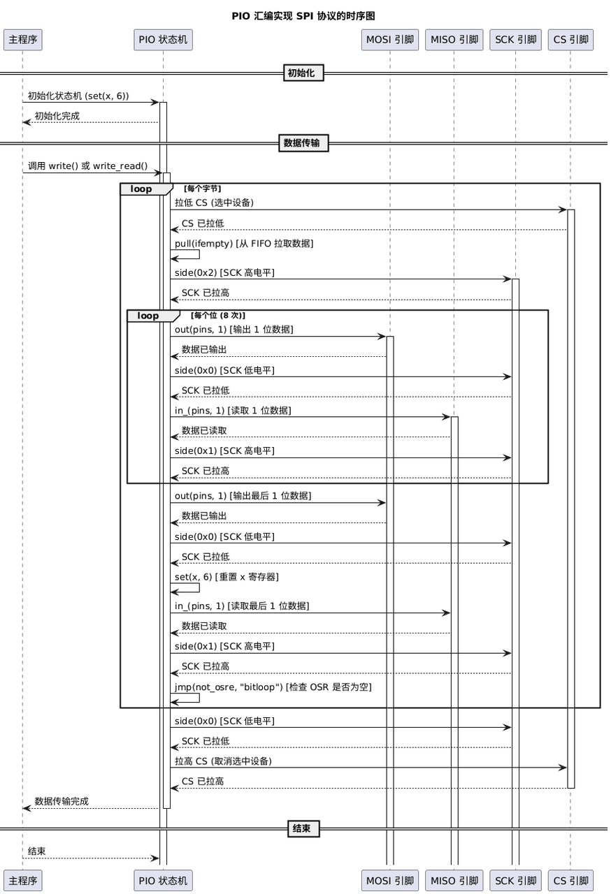
In short, we mainly implement SPI communication through PIO with the following steps:
In each clock cycle, each data bit is moved from the output shift register (OSR) to the MOSI pin through the shift register, sent on the falling edge of the clock, and sampled on the rising edge of the clock.
The x register controls the number of data bit transmissions per byte; after each byte is transmitted, the program prepares the next byte of data.
The side() instruction controls the level changes of the SPI clock (SCK) pin, ensuring that the data sending and sampling timing meets the requirements of CPHA=0, CPOL=0.
Next, we encapsulated the function of implementing SPI communication with a PIO state machine in the custom PIOSPI class, and provided the following methods:
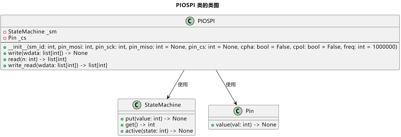
Initialization init() method: initialize the PIO state machine, specify parameters such as sm_id (state machine number), pin_mosi (data output pin), pin_miso (data input pin), pin_sck (clock pin), and set the frequency to 4*freq to match the clock cycles of PIO instructions (each data bit-level operation takes one clock cycle), then activate the state machine to prepare for data transmission.
Write write() method: use self._sm.put() to shift each byte left by 24 bits (aligned to the highest bit) and put it into the TX FIFO. This method is blocking and needs to wait until all data has been sent.
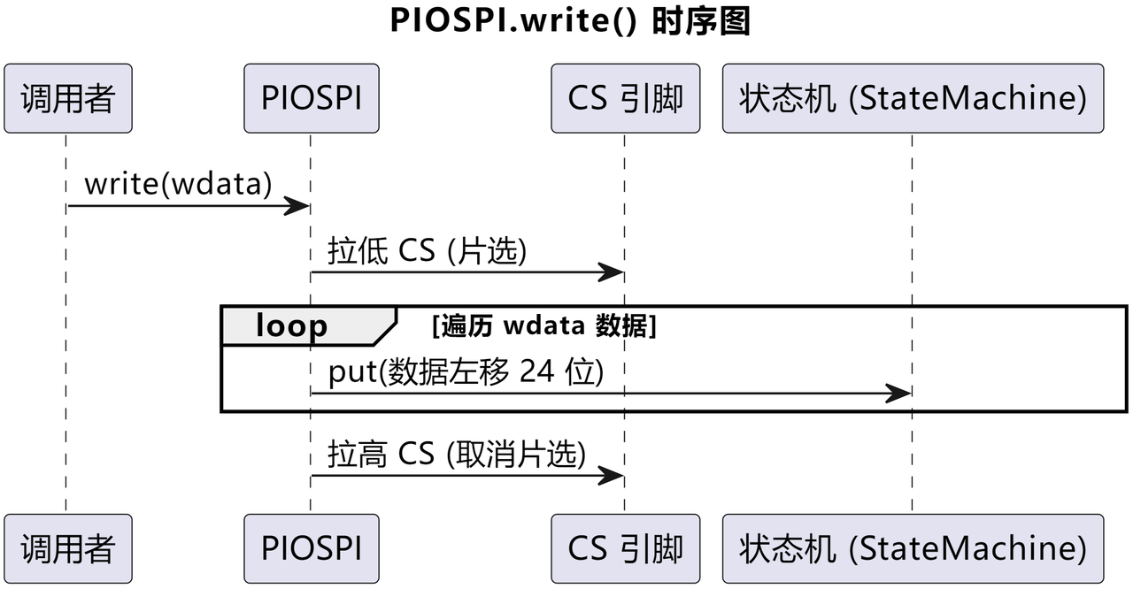
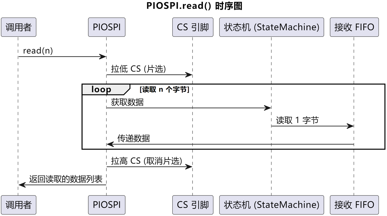
Read read() method: use self._sm.get() to read data from the RX FIFO byte by byte, and use & 0xff to extract the lowest 8 bits, ensuring the data is within one byte. It is also a blocking method.
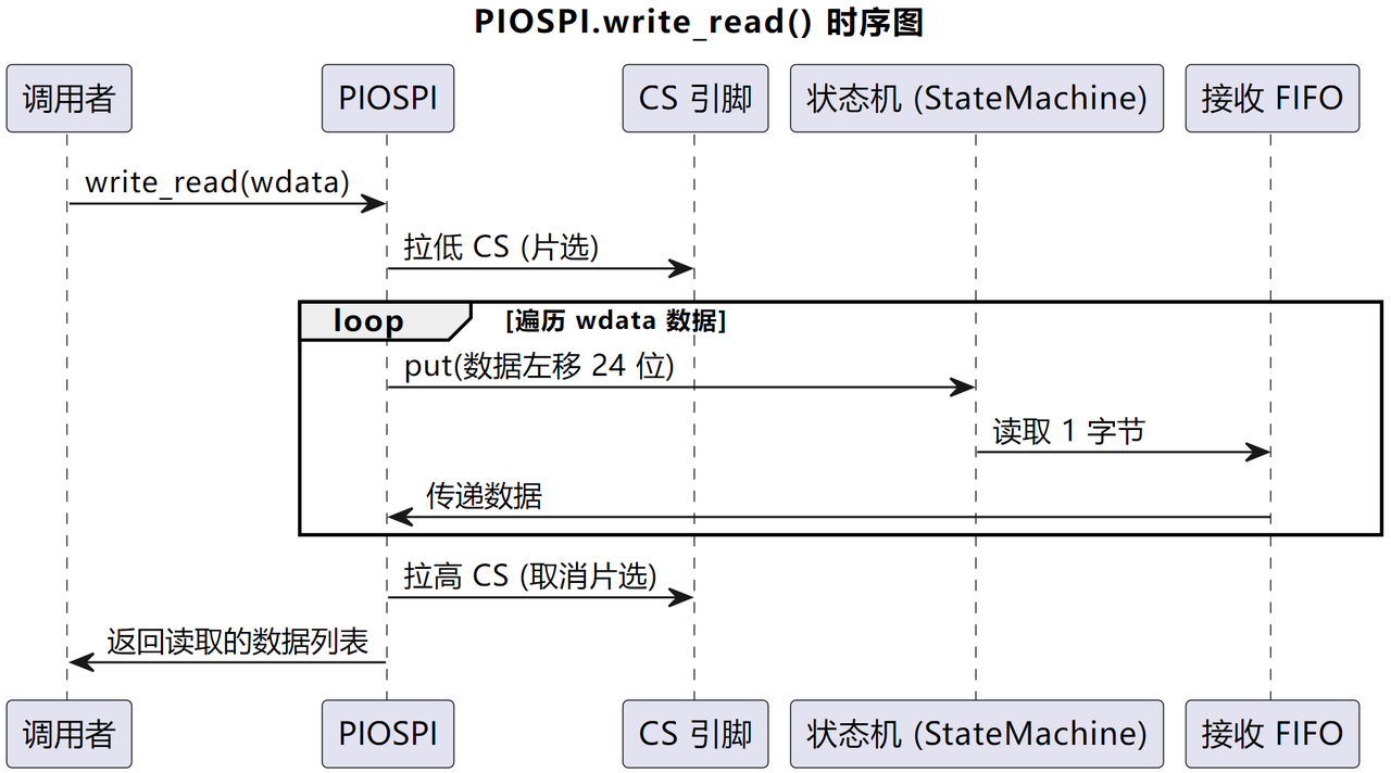
Read/write write_read() method: send and receive data at the same time, use put to send each byte and call get to receive the corresponding response data.
Note that, because the PIO assembly program involves sideset operation settings, it is required that the pin_mosi number and the pin_sck number are adjacent, and the pin_mosi number is smaller than the pin_sck number.
2. SPI Data Transmit/Receive Loopback Test
The following code can be found in the elegance-devkit v1\Demo\36 PIO_SPI folder in our resource package.
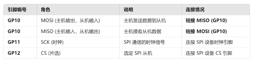
In the main program, we use the custom PIOSPI class to send data to an external device. The main program sends a group of byte data every second, and sets the MOSI pin and MISO pin to the same pin to perform a data transmit/receive loopback test. The sample code is as follows:
# Python env : MicroPython v1.23.0
# -*- coding: utf-8 -*-
# @Time : 2024/11/6 6:41 PM
# @Author : Li Qingshui
# @File : main.py
# @Description : Loopback test of data transmission and reception using the SPI protocol simulated by PIO
# ======================================== Import related modules ========================================
# Import time-related modules
import time
# Import the PIO-simulated SPI protocol module
from pio_spi import PIOSPI
# ======================================== Global variables ============================================
# Byte list to be sent
tx_list = [0, 1, 2, 3, 4, 5, 6, 7]
# ======================================== Function definitions ============================================
# ======================================== Custom classes ============================================
# ======================================== Initialization configuration ==========================================
# Delay to wait for device initialization
time.sleep(3)
# Print debug information
print('FreakStudio : Using PIO to implement the SPI protocol')
# Initialize the SPI class, setting the baud rate, polarity, phase, clock pin, and data pins
# Set pin_mosi and pin_miso to GP10, pin_sck to GP11, pin_cs to GP12, CPHA to False, CPOL to False, and baud rate to 1000000
# Set MISO and MOSI to the same pin for the transmit/receive loopback test
spi = PIOSPI(sm_id=0, pin_mosi=10, pin_sck=11, pin_miso=10, pin_cs = 12,cpha=False, cpol=False, freq=1000000)
# ======================================== Main program ===========================================
# Use PIO-simulated SPI protocol to send and receive data
while True:
# Send and read data
data = spi.write_read(tx_list)
# Print debug information
print('FreakStudio : SPI data received : {}'.format(data))
# Wait 1 second
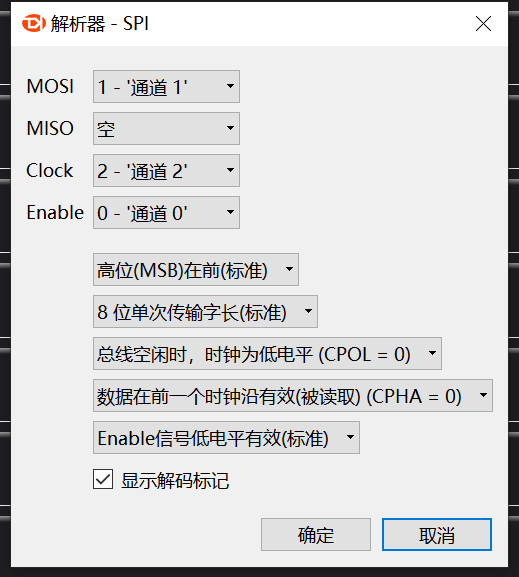
time.sleep(1)Before flashing the code, we need to add an SPI protocol parser in the KingST logic analyzer software and make the following settings:
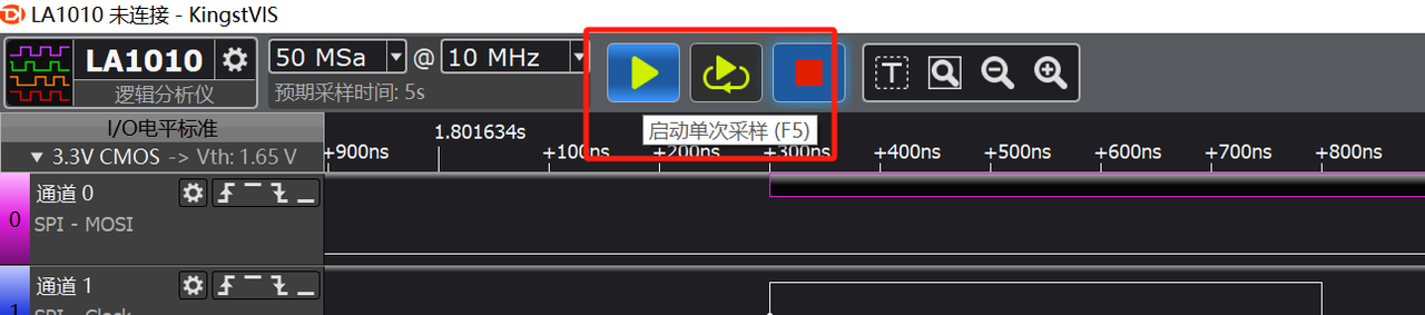
Then flash the code, open the terminal, open the logic analyzer host software, and click to start single sampling:
The output is as follows:
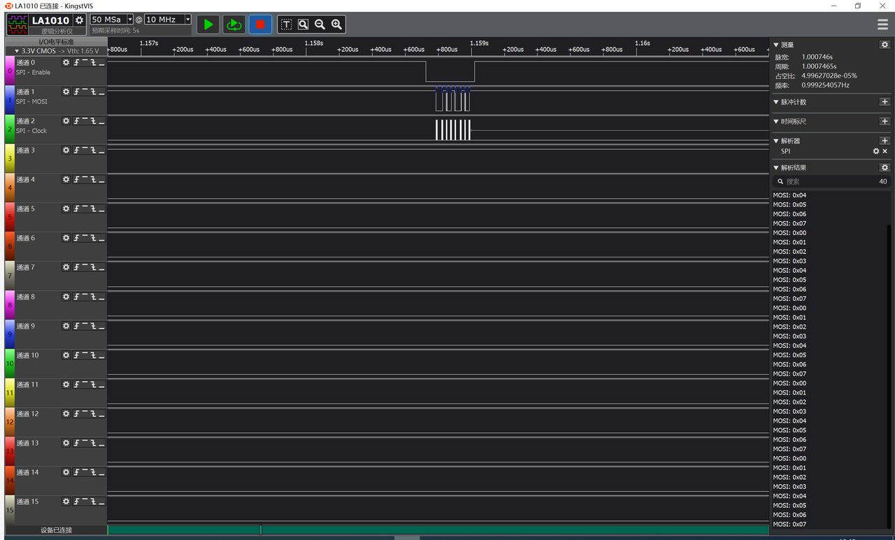
We can see that we successfully used PIO to simulate the SPI protocol and send data:
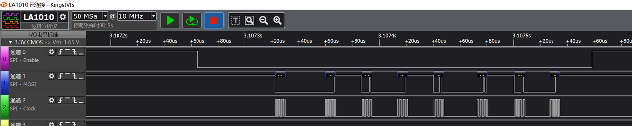
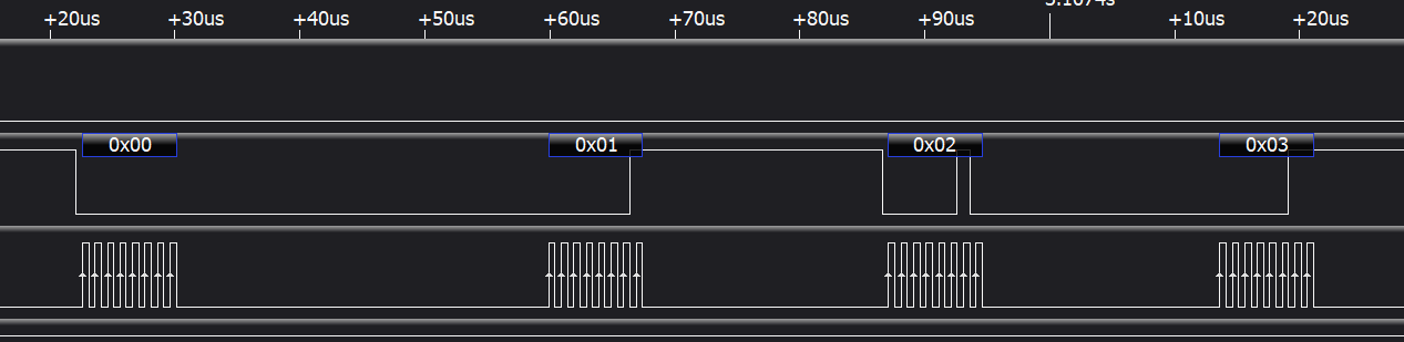
The clock frequency is consistent with the communication frequency preset in the program:

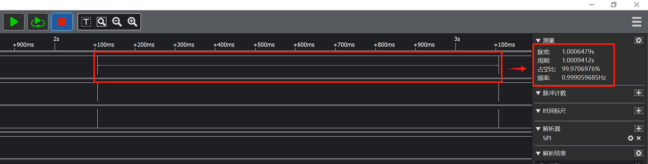
The CS chip select timing is basically the same as the settings: pulling it low indicates the start of sending, and pulling it high indicates the end of sending. The data transmit/receive period is about 1 second:

Open the terminal and use the mpremote tool to connect to the Raspberry Pi Pico; you can see that the custom PIOSPI class can complete data reception: