From DREQ to Interrupt: A Full Analysis of the "Express Delivery System" of RP2040 DMA
This article explains RP2040 DMA controller, its working modes, channel chaining, DREQ trigger mechanism and interrupt configuration.
COMPONENTS
PROJECT DESCRIPTION
DMA
The core responsibility of a kernel is to "compute and process tasks". If it is required to manually move data (such as reading data from a sensor and storing it in memory), computing resources will be wasted, as the kernel cannot handle other tasks while moving data. In contrast, DMA is a "dedicated data transfer tool" that can efficiently complete bulk data transmission, allowing the kernel to handle other tasks or even enter low-power sleep mode, which improves efficiency and saves power at the same time.
The DMA (Direct Memory Access) controller has separate read and write master connections to the bus architecture, and can perform bulk data transfers on behalf of the processor. This allows the processor to freely handle other tasks or enter a low-power sleep state.
For individual read and write operations, DMA can handle a maximum of 32-bit data, features 12 independent channels, and each channel monitors a sequence of bus transmissions.
DMA is typically used for data transmission in the following three scenarios:
Memory to Peripheral: When more data is required, the peripheral sends a signal to the DMA controller, which then reads data from the array located in RAM or flash and writes it to the data FIFO of the peripheral device;
Peripheral to Memory: When a peripheral receives data from an external sensor or communication interface, it sends a signal to the DMA. The DMA reads this data from the peripheral's data FIFO and writes it to an array in RAM;
Memory-to-memory: DMA transfers data between two buffers in RAM.
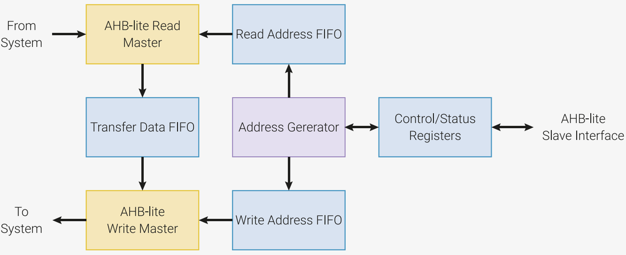
Figure 2.17 Architecture Block Diagram of RP2040 DMA Controller
The architecture diagram illustrates the "internal workflow" of DMA, and the functions of each module are as follows:
AHB-lite Read/Write Master Bus: it is the interface for DMA to connect to the system bus (AHB-lite):
Read Master: responsible for reading data from the system (memory/peripheral devices);
Write Master: Responsible for writing data to the system (memory/peripheral devices).
Read/Write Address FIFO: FIFO stands for "First-In-First-Out buffer", which stores the addresses to be read from or written to (for example, when a transfer starts at memory address 0x20000000, the address will be stored here). It caches address requests, preventing laggy performance caused by the mismatched pacing between address generation and data transfer.
Transfer Data FIFO: It stores the data being transferred, serving the same buffering purpose to align the rhythm of "address request" and "data transfer" and ensure smooth transmission.
Address Generator: The "automatic address calculator" of DMA: for example, if you need to transfer 100 consecutive bytes starting from 0x20000000 in memory, it will automatically generate consecutive addresses such as 0x20000000,0x20000001.. . without the kernel having to calculate addresses manually.
Control/Status Registers: serve as the control center and status indicator for DMA:
Control: The software configures DMA here (e. g., the transfer direction, whether it is "peripheral to memory" or "memory to peripheral", the data size, 8/16/32 bits, and the amount of data to be transferred);
Status: The software allows you to check the transmission progress here, such as how much data has been transferred, whether the transfer is completed, and whether any errors have occurred.
AHB-lite Slave Interface: serves as the "entry point for kernel to configure DMA": through this interface, the kernel writes configuration parameters to the Control/Status Registers, instructing the DMA on "what data to transfer and how to transfer it".
Next, let's take the "peripheral to memory" transfer (e. g., storing sensor data into memory) as an example:
The kernel writes configurations to the Control/Status Registers via the AHB-lite Slave Interface, such as setting the source address to the FIFO address of the sensor, the destination address to the memory array address, and the transfer length to 100 bytes.
Address Generator automatically generates the peripheral address to be read and the memory address to be written, and stores them in the Read Address FIFO and Write Address FIFO respectively;
AHB-lite Read Master reads data from the peripheral and places it into the Transfer Data FIFO buffer;
AHB-lite Write Master fetches data from the Transfer Data FIFO and writes it to the target memory address;
During the entire process, the kernel does not need to participate, and the whole process is completed automatically by DMA entirely.
Each channel of DMA is equipped with a corresponding status register, through which software can program and monitor the progress of data read and write operations for that channel. We can visualize each DMA channel as an independent courier, and the status register serves as the "task list + work log" for this courier:
Programming (register writing): Before the assistant sets off, you (the software) write the task in the logbook — for example, "transfer 100 pieces of data from location A in memory to the UART peripheral" and "follow the DREQ signal of the UART when transferring data", which is exactly the process of configuring a task for the DMA channel;
Monitor Progress (Reading Registers): When the DMA controller is working, it will record its progress in real time in a log book — such as "50 data units have been transferred", "Task completed", "An error occurred during data transfer". You (the software) can check the log book at any time to know the working status of this DMA channel, without having to keep staring at it while it operates.
The size of DMA transfer data can be 32 bits, 16 bits or 8 bits. Each channel is configured once: the source transfer size is the same as the destination transfer size:
This defines the "data transfer packetization mode" for DMA: when DMA transfers data each time, it can choose to transfer 1 byte (8 bits), 2 bytes (16 bits), or 4 bytes (32 bits)(equivalent to a courier carrying 1 parcel, 2 parcels, or 4 parcels at a time);
The source and destination sizes must be identical: this means the packaging method for "where to move data from" and "where to move data to" must be consistent — you cannot move 4 bytes (32 bits) at a time from memory while only writing 1 byte (8 bits) at a time to an external device, otherwise data corruption will occur (just like a courier carrying 4 packages at once but only able to stuff 1 into the parcel locker, leaving the rest to drop on the ground);
Configure each channel only once: once a DMA channel is set to use 32-bit transmission, it will stick to 32-bit transmission throughout the entire task without any mid-process changes; if you need to switch the transmission mode, you have to reconfigure this channel.
DMA different channels can be combined with each other. For example, one channel can configure another channel by loading configuration data from a series of control blocks in memory, and then when reconfiguration is required, the second channel can call the first channel through the CHAIN_TO option:
This refers to the "relay operation" or "mutual coordination" function of DMA channels, which enables multiple DMA channels to collaborate on complex tasks without the need for the software (kernel) to intervene midway;
Suppose you have two DMA channels: Channel 1 acts as the "configurator", and Channel 2 serves as the "data mover":
First, store in memory the configurations for multiple sets of transfer tasks (e. g., "Task 1: Transfer 100 pieces of 32-bit data to UART0", "Task 2: Transfer 200 pieces of 8-bit data to SPI0", "Task 3: Copy data from Memory A to Memory B"); these configurations are called "control blocks".
You configure the initial task for Channel 2: "First, locate Channel 1, instruct it to read the first set of control blocks (Task 1) from memory, and then operate in accordance with this control block. "
After channel 2 completes task 1, no software (kernel) reconfiguration is required, and it can use the CHAIN_TO option (equivalent to "call chaining") to let channel 1 read the second set of control blocks (task 2) from memory, after which channel 2 proceeds to execute task 2; this process repeats until all tasks corresponding to the control blocks are finished.
Meanwhile, DMA can also work in coordination with other peripherals, and data is directly transferred between peripherals and DMA via DREQ channels. The so-called DREQ is a "signal" sent by the peripheral to the DMA, notifying the DMA that "I am ready to receive/transmit data, and you can start the transfer":
For example, when the UART needs to transmit data: once the transmit FIFO of the UART is empty, it will send a DREQ signal to the DMA, and after receiving the signal, the DMA will transfer the data from the memory to the FIFO of the UART;
For example, when the UART is to receive data: when the receive FIFO of the UART is full, it sends a DREQ to the DMA, and the DMA then fetches the data from the FIFO into the memory.
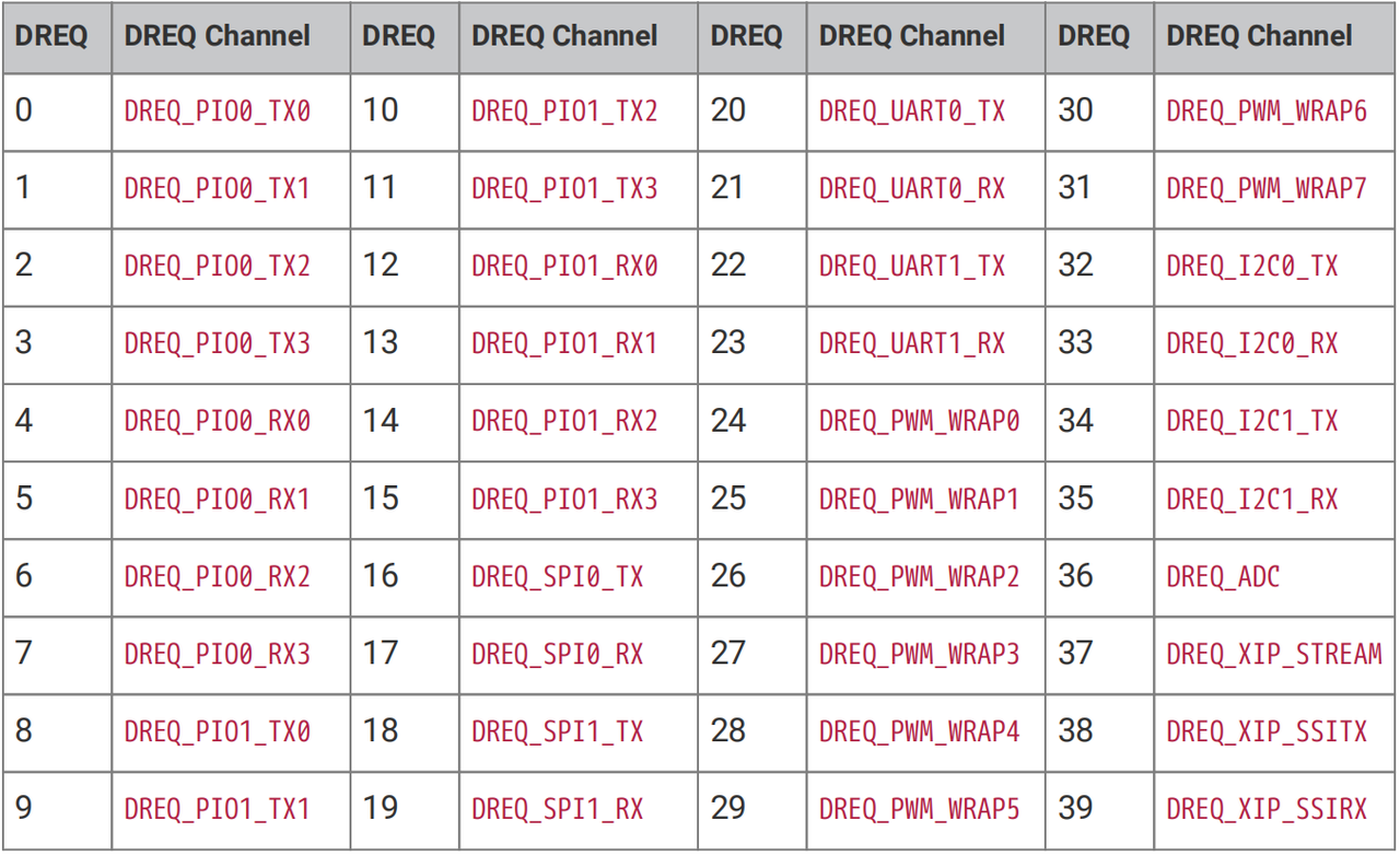
The correspondence between different peripherals and DREQ channels can be found in the DREQ table, which is a list mapping "peripheral functions → DREQ channels", where each DREQ number corresponds to the transmit/receive function of a peripheral:
Figure 2.18 RP2040 Peripheral DREQ channel and DMA mapping table
Taking the above table as an example, we can see that:
DREQ20 corresponds to "UART0_TX"(the transmission request of UART0);
DREQ17 corresponds to "SPI0_RX"(the receive request of SPI0).
DMA can also be used in conjunction with interrupts: when data read/write of a certain channel in DMA is completed, an interrupt can be triggered to prompt the program to perform corresponding operations (for example, after data transmission is finished, the kernel will analyze these data).
Let's compare DMA channels to couriers in charge of different delivery tasks, and the kernel is the "boss" of the company;
As mentioned earlier, when the worker is on the job, the boss can slack off (handle other tasks) or go to sleep (enter low-power hibernation) without having to keep an eye on the worker;
After the clerk finishes moving a batch of data (for example, storing all 100 data points from the sensor into memory), he cannot directly go to the boss — instead, he will press an "emergency call bell", which is the interrupt;
As soon as the boss hears the bell ring, he knows "one of the guys has finished the task", then puts down whatever he is doing and proceeds with the follow-up work, such as analyzing the data from the newly delivered sensor, transferring the data to a USB flash drive, and clearing the memory to prepare for the next data transfer.
Simply put, after DMA completes its task, it triggers an interrupt to send a "completion notification" to the kernel, allowing the kernel to handle subsequent tasks in a timely manner without constantly polling "Has the DMA finished? Has it finished yet? ", which not only saves the kernel's resources but also ensures the timeliness of tasks.
The RP2040 DMA provides two system IRQs with separate masking and status registers (e. g., INTE0, INTE1). Any combination of channel interrupt requests can be routed to either of the system IRQs:
First explain the key terms in this passage, then connect them with examples:
System IRQs :can be analogized to the two "general customer service hotlines"(IRQ0 and IRQ1, corresponding to INTE0 and INTE1 respectively), through which all the "completion notifications"(interrupt requests) from the DMA messengers are routed to the boss (the kernel).
Mask Register: Here, "mask" means to block or mute. This register acts as the mute switch for hotlines — for example, you can configure it to "block notifications from Staff 1 from reaching Hotline 0", or "mute Hotline 1 temporarily and route all notifications to Hotline 0", so as to prevent non-essential notifications from disturbing the supervisor.
Status Register: It is equivalent to a "call log" for the hotline, which records entries such as "Notification from Staff 3 is incoming" and "Task from Staff 7 has been completed". When the manager checks this log, he will know which staff's follow-up tasks need to be handled.
Routing refers to "allocating and directing" — you can freely assign which courier's notification goes through which dedicated line.
The DMA of the RP2040 has 12 channels (12 little helpers), but only 2 customer service hotlines (two system IRQs) are reserved. You can configure it as follows:
Route the notifications from Operator 1 (sensor data handling) and Operator 2 (UART data transmission) to Hotline 0 (INTE0);
Route the notifications from Agent 3 (memory copy) and Agent 4 (SPI data transmission) to Hotline 1 (INTE1);
You can even route all notifications for a specific courier to the same hotline, or have notifications from certain couriers sent to two hotlines simultaneously.
If you consider the task of Worker 3 unimportant, you can also use the mask register to block Worker 3's notifications. Even after he finishes the task, he will not be able to get through to the hotline, and the boss will not receive any notification from him.
The advantage of this design is that: it enables flexible management of interrupts from multiple DMA channels to avoid interrupt signal confusion, and meanwhile allows the kernel to process different types of DMA tasks according to the priority of the hotline (for instance, routing urgent tasks to hotlines with higher priorities).