



Fix MicroPython ADC Main‑Loop Lag: DMA + Ping‑Pong Buffering
RP2040 DMA ping‑pong buffer solves MicroPython ADC main‑loop slowdown
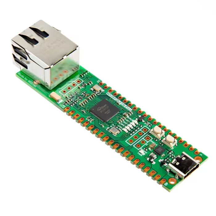
- Pre‑experiment Preparation
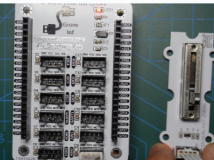
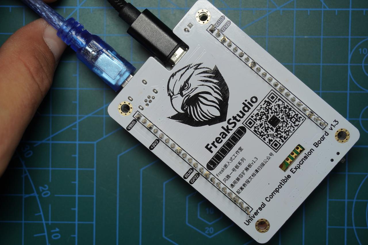
For this experiment, insert Elegance‑One Grove‑Interface Expansion Board onto Elegance‑One Universal Compatible Expansion Board. Use a PH2.0‑4P cable to connect the AIN0 port on the Elegance‑One Grove‑Interface Expansion Board to the analog‑output port of the GraftSense‑Slide‑Potentiometer Module.
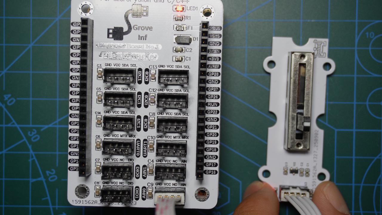
Additionally connect Mini‑USB cable to serial port on Elegance‑One Universal Compatible Expansion Board. GP0 and GP1 are default hardware UART0 pins for Raspberry‑Pi Pico.
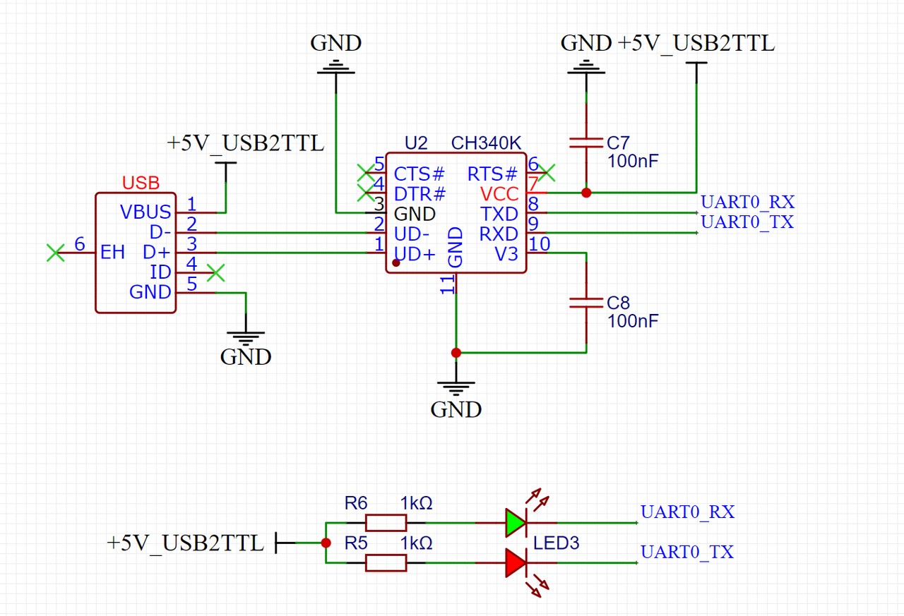
Physical photo after assembly:
Pin‑assignment table:
- Implementation of Custom ADC DMA‑Transfer Class
Define a DMA_ADC_Transfer class for Raspberry‑Pi Pico. It uses DMA to move ADC sample data from the FIFO register into system memory.
Sample code:
# Python env   : MicroPython v1.23.0
# -*- coding: utf-8 -*-
# @Time    : 2024/9/8 11:15 PM
# @Author  : Li Qingshui
# @File    : dma_adc_trans.py.py
# @Description : Custom ADC data acquisition DMA‑transfer class
# ======================================== Import related modules =========================================
# Import hardware‑related modules
from machine import ADC
# Import addressof function to fetch object memory address
from uctypes import addressof
# Import DMA‑related modules
from rp2 import DMA
# Import 32‑bit memory‑access module
from machine import mem32
# ======================================== Global variables ============================================
# ======================================== Function definitions ============================================
# ======================================== Custom classes ============================================
# Custom ADC class for DMA‑assisted data transfer
class DMA_ADC_Transfer:
    """
    DMA_ADC_Transfer class for high‑speed ADC data transfer via DMA.
    This class encapsulates ADC configuration, DMA transfer and FIFO control. It implements high‑speed sampling into user‑provided buffer.
    Free‑running sampling mode is supported, ADC sample rate is configurable. Both blocking and non‑blocking DMA‑transfer modes are available.
    Attributes:
        buf (bytearray): Buffer for storing ADC samples.
        sample_rate (int): Target ADC sample rate in Hz.
        adc (ADC): ADC peripheral instance.
        dma (DMA): DMA‑controller instance.
    Constants:
        DREQ_ADC (int): DMA trigger‑request ID for ADC.
        ADC_BASE (int): Base address of ADC FIFO registers.
        CS_REG (int): Offset address for control‑status register CS.
        RESULT_REG (int): Offset address for result register RESULT.
        FCS_REG (int): Offset address for FIFO‑control register FCS.
        DIV_REG (int): Offset address for clock‑divider register DIV.
        FIFO_REG (int): Offset address for FIFO‑data register FIFO.
        FIFO_THRESH (int): FIFO threshold that triggers DMA transfer.
        ADC_CLOCK_FREQ (int): ADC clock frequency, fixed at 48 MHz.
    Methods:
        __init__(self, buf: bytearray, sample_rate: int = 1000, adc_id: int = 0):
            Initialize DMA_ADC_Transfer instance and configure ADC and DMA peripherals.
        configure_adc_fifo(self) -> None:
            Configure ADC FIFO to work cooperatively with DMA.
        start_adc_continuous(self) -> None:
            Start ADC free‑running continuous‑sampling mode.
        configure_adc_sample_rate(self, sample_rate: int) -> None:
            Set ADC sample rate and program corresponding clock divider.
        stop_dma_adc_fifo(self) -> None:
            Stop DMA transfer and ADC sampling for safe shutdown.
        start_dma_transfer(self, wait_func: callable = None, complete_callback: callable = None, blocking: bool = True) -> None:
            Launch DMA transfer, optional blocking‑wait and completion callback.
        close(self) -> None:
            Close DMA channel and release ADC resources.
    """
    # DMA trigger‑request signal ID for ADC
    DREQ_ADC = 36
    # Base memory address for ADC FIFO registers
    ADC_BASE = 0x4004C000
    # CS register offset 0x00
    CS_REG = ADC_BASE + 0x00
    # RESULT register offset 0x04
    RESULT_REG = ADC_BASE + 0x04
    # FCS FIFO‑control register offset 0x08
    FCS_REG = ADC_BASE + 0x08
    # DIV clock‑divider register offset 0x10
    DIV_REG = ADC_BASE + 0x10
    # FIFO data register offset 0x0C
    FIFO_REG = ADC_BASE + 0x0C
    # ADC FIFO trigger threshold
    FIFO_THRESH = 1
    # ADC clock frequency fixed at 48 MHz
    ADC_CLOCK_FREQ = 48_000_000

    def __init__(self, buf: bytearray, sample_rate: int = 1000, adc_id: int = 0) -> None:
        """
        Initialize DMA_ADC_Transfer instance.
        Args:
            buf (bytearray): User‑supplied data buffer object.
            sample_rate (int): Target sample rate in Hz, default 1000.
            adc_id (int): ADC peripheral ID, 0 / 1 / 2, default 0.
        Raises:
            TypeError: buf is not bytearray.
            ValueError: adc_id invalid or sample‑rate out‑of‑range.
        """
        if not isinstance(buf, bytearray):
            raise TypeError("buf must be bytearray")
        if adc_id not in (0, 1, 2):
            raise ValueError("adc_id must be 0, 1 or 2")
        self.buf = buf
        self.sample_rate = sample_rate
        self.adc = ADC(adc_id)
        self.dma = DMA()
        self.configure_adc_fifo()
        self.configure_adc_sample_rate(self.sample_rate)
        self.start_adc_continuous()

    def configure_adc_fifo(self) -> None:
        """
        Configure ADC FIFO for DMA cooperation.
        FIFO output is right‑shifted by 4‑bit, converting original 12‑bit ADC result into 8‑byte value (0‑255).
        Returns:
            None
        """
        fcs_value = mem32[DMA_ADC_Transfer.FCS_REG]
        mem32[DMA_ADC_Transfer.FCS_REG] = fcs_value | (1 << 0) | (1 << 3) | (1 << 1)
        mem32[DMA_ADC_Transfer.FCS_REG] |= (DMA_ADC_Transfer.FIFO_THRESH << 24)

    def start_adc_continuous(self) -> None:
        """
        Enable free‑running sampling mode by setting START_MANY bit.
        ADC will automatically launch new conversions at configured intervals.
        Returns:
            None
        """
        cs_value = mem32[DMA_ADC_Transfer.CS_REG]
        mem32[DMA_ADC_Transfer.CS_REG] = cs_value | (1 << 3)

    def configure_adc_sample_rate(self, sample_rate: int) -> None:
        """
        Configure ADC sampling rate.
        Args:
            sample_rate (int): Target sample rate in Hz.
        Returns:
            None
        Raises:
            ValueError: sample‑rate out‑of‑valid range.
        """
        if sample_rate <= 0 or sample_rate > 48_000_000:
            raise ValueError("sample rate out of range")
        if sample_rate < 1000:
            raise ValueError("sample rate too low")
        total_period = 48_000_000 / sample_rate
        int_part = int(total_period) - 1
        frac_part = int((total_period - int_part - 1) * 256)
        mem32[DMA_ADC_Transfer.DIV_REG] = (int_part << 8) | frac_part

    def stop_dma_adc_fifo(self) -> None:
        """
        Terminate DMA transfer and ADC sampling.
        Returns:
            None
        """
        adc_cs_value = mem32[DMA_ADC_Transfer.CS_REG]
        adc_cs_value &= ~(1 << 3)
        mem32[DMA_ADC_Transfer.CS_REG] = adc_cs_value
        while not ((mem32[DMA_ADC_Transfer.CS_REG]>>8) & 0x1):
            pass

    def start_dma_transfer(self, wait_func: callable = None, complete_callback: callable = None, blocking: bool = True) -> None:
        """
        Launch DMA transfer.
        Args:
            wait_func (callable): Optional callback invoked while waiting for completion.
            complete_callback (callable): Optional callback invoked upon transfer finish.
            blocking (bool): True = block thread until transfer finishes, default True.
        Returns:
            None
        Raises:
            ValueError: wait_func supplied under non‑blocking mode.
        """
        if blocking == False and wait_func is not None:
            raise ValueError("wait_func must be None when blocking is False")
        if complete_callback is not None:
            self.dma.irq(handler=complete_callback, hard=True)
        ctrl = self.dma.pack_ctrl(
            enable=True,
            size=0,
            inc_read=False,
            inc_write=True,
            treq_sel=DMA_ADC_Transfer.DREQ_ADC,
            irq_quiet = False
        )
        self.dma.config(
            read=self.FIFO_REG,
            write=addressof(self.buf),
            count=len(self.buf),
            ctrl=ctrl,
            trigger=False
        )
        self.dma.active(1)
        if blocking == True:
            while self.dma.active():
                if wait_func is not None:
                    wait_func()
        else:
            return

    def close(self) -> None:
        """
        Release DMA channel resource and stop ADC peripheral.
        Returns:
            None
        """
        self.dma.close()
        self.stop_dma_adc_fifo()
# ======================================== Initialization ==========================================
# ======================================== Main program ===========================================
DMA controller fetches ADC samples from ADC FIFO register, triggered by ADC_DREQ hardware request signal. Configuration workflow:
- Enable FIFO (
FCS.EN). FIFO must be turned‑on so ADC conversion results get written into FIFO storage. FIFO stays disabled by default to prevent accidental sample accumulation during single‑shot conversions. - Enable ADC DMA request (
FCS.DREQ_EN). The ADC DREQ handshake signal must be enabled so DMA can read samples from FIFO on‑demand. - Select
DREQ_ADCas DMA‑channel trigger source. Selected DMA channel must use ADC DREQ signal for hardware‑synchronized transfers. - Set DREQ assertion threshold (
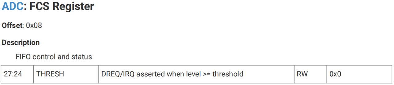
FCS.THRESH). Set threshold value to 1 so DMA fires as soon as one sample exists inside FIFO. Note this threshold also controls IRQ trigger level; higher values may be needed for non‑DMA scenarios to reduce interrupt frequency.
- Configure for 8‑bit DMA transfers (
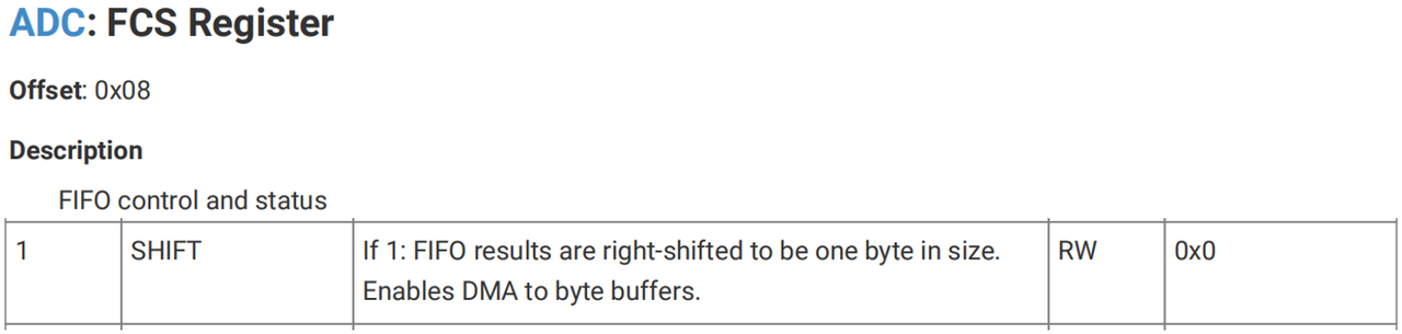
FCS.SHIFT). When DMA moves bytes into bytearray buffers, enable FCS.SHIFT to right‑shift raw 12‑bit ADC samples down to 8‑bit byte values.
- Program ADC sample rate (
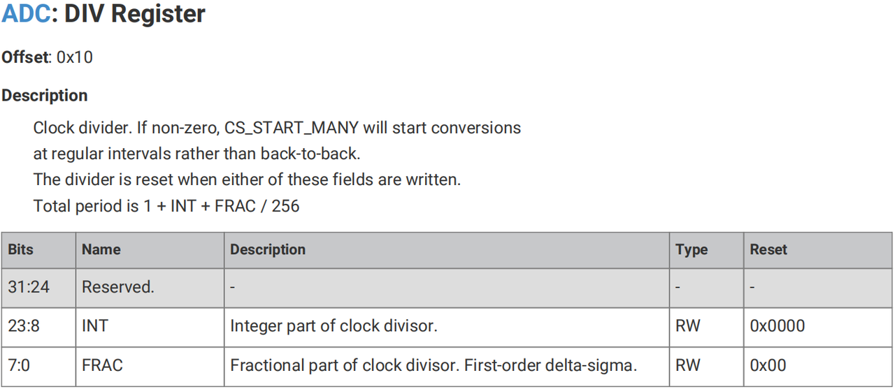
DIVregister). Set sampling clock divider value before starting ADC conversions.
- Activate free‑running sampling mode (
CS.START_MANY). Enables continuous repeated ADC conversions.
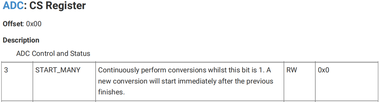
- Activate DMA channel to start sample streaming. After DMA completes one full buffer transfer, you may stop ADC or immediately restart a new DMA job.
- Clear
CS.START_MANYbit to halt ADC conversions. Software must pollCS.READYstatus bit to guarantee completion of last conversion and drain leftover samples from FIFO.
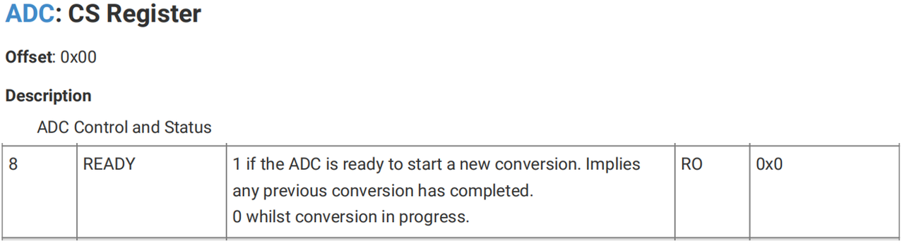
Methods inside custom DMA_ADC_Transfer class:
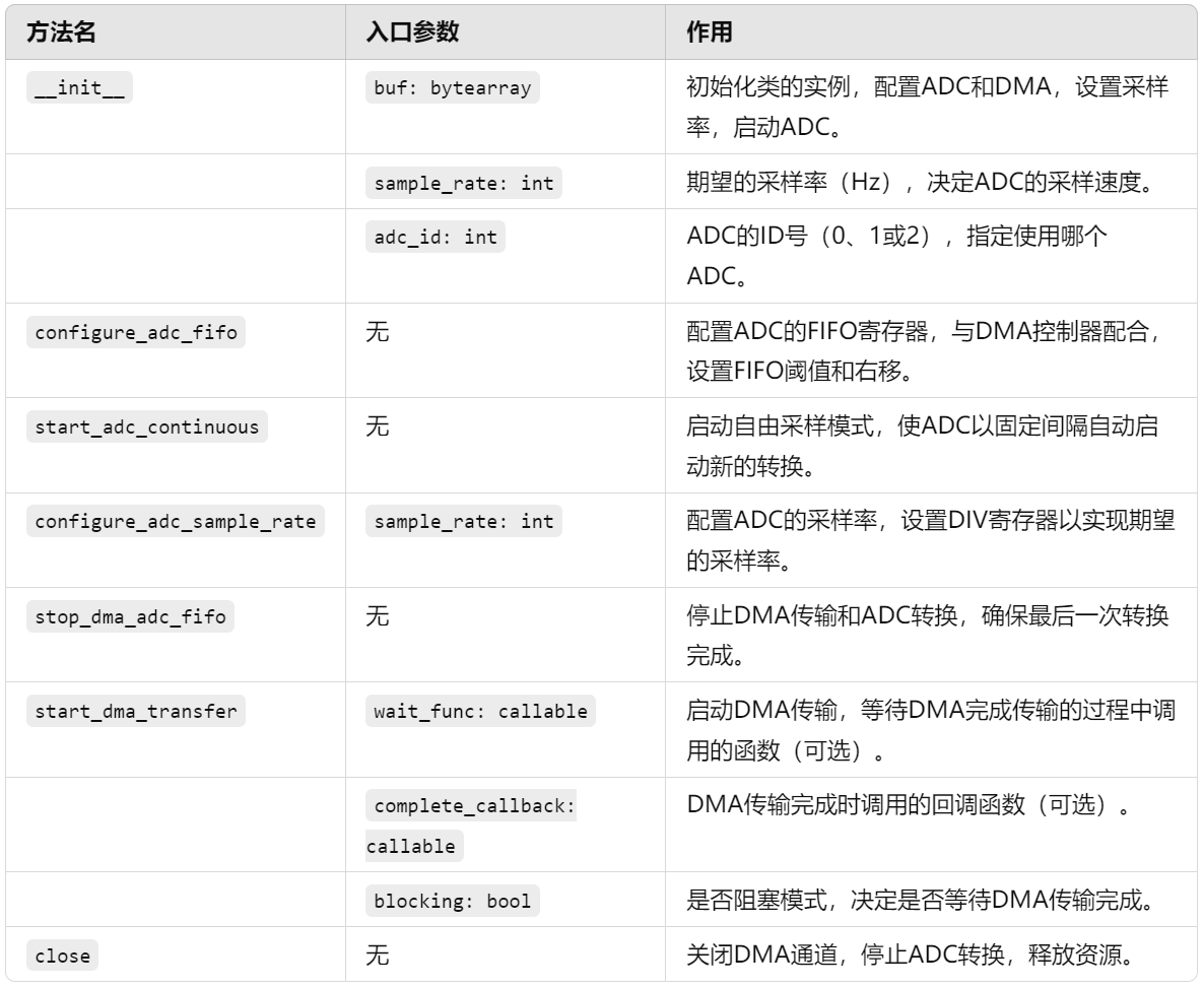
Initialization method completes all ADC‑related DMA‑peripheral setup:
# Custom ADC class for DMA‑assisted data transfer
class DMA_ADC_Transfer:
    """
    DMA_ADC_Transfer class for high‑speed ADC data transfer via DMA.
    This class encapsulates ADC configuration, DMA transfer and FIFO control. It implements high‑speed sampling into user‑provided buffer.
    Free‑running sampling mode is supported, ADC sample rate is configurable. Both blocking and non‑blocking DMA‑transfer modes are available.
    Attributes:
        buf (bytearray): Buffer for storing ADC samples.
        sample_rate (int): Target ADC sample rate in Hz.
        adc (ADC): ADC peripheral instance.
        dma (DMA): DMA‑controller instance.
    Constants:
        DREQ_ADC (int): DMA trigger‑request ID for ADC.
        ADC_BASE (int): Base address of ADC FIFO registers.
        CS_REG (int): Offset address for control‑status register CS.
        RESULT_REG (int): Offset address for result register RESULT.
        FCS_REG (int): Offset address for FIFO‑control register FCS.
        DIV_REG (int): Offset address for clock‑divider register DIV.
        FIFO_REG (int): Offset address for FIFO‑data register FIFO.
        FIFO_THRESH (int): FIFO threshold that triggers DMA transfer.
        ADC_CLOCK_FREQ (int): ADC clock frequency, fixed at 48 MHz.
    Methods:
        __init__(self, buf: bytearray, sample_rate: int = 1000, adc_id: int = 0):
            Initialize DMA_ADC_Transfer instance and configure ADC and DMA peripherals.
        configure_adc_fifo(self) -> None:
            Configure ADC FIFO to work cooperatively with DMA.
        start_adc_continuous(self) -> None:
            Start ADC free‑running continuous‑sampling mode.
        configure_adc_sample_rate(self, sample_rate: int) -> None:
            Set ADC sample rate and program corresponding clock divider.
        stop_dma_adc_fifo(self) -> None:
            Stop DMA transfer and ADC sampling for safe shutdown.
        start_dma_transfer(self, wait_func: callable = None, complete_callback: callable = None, blocking: bool = True) -> None:
            Launch DMA transfer, optional blocking‑wait and completion callback.
        close(self) -> None:
            Close DMA channel and release ADC resources.
    """
    # DMA trigger‑request signal ID for ADC
    DREQ_ADC = 36
    # Base memory address for ADC FIFO registers
    ADC_BASE = 0x4004C000
    # CS register offset 0x00
    CS_REG = ADC_BASE + 0x00
    # RESULT register offset 0x04
    RESULT_REG = ADC_BASE + 0x04
    # FCS FIFO‑control register offset 0x08
    FCS_REG = ADC_BASE + 0x08
    # DIV clock‑divider register offset 0x10
    DIV_REG = ADC_BASE + 0x10
    # FIFO data register offset 0x0C
    FIFO_REG = ADC_BASE + 0x0C
    # ADC FIFO trigger threshold
    FIFO_THRESH = 1
    # ADC clock frequency fixed at 48 MHz
    ADC_CLOCK_FREQ = 48_000_000

    def __init__(self, buf: bytearray, sample_rate: int = 1000, adc_id: int = 0) -> None:
        """
        Initialize DMA_ADC_Transfer instance.
        Args:
            buf (bytearray): User‑supplied data buffer object.
            sample_rate (int): Target sample rate in Hz, default 1000.
            adc_id (int): ADC peripheral ID, 0 / 1 / 2, default 0.
        Raises:
            TypeError: buf is not bytearray.
            ValueError: adc_id invalid or sample‑rate out‑of‑range.
        """
        if not isinstance(buf, bytearray):
            raise TypeError("buf must be bytearray")
        if adc_id not in (0, 1, 2):
            raise ValueError("adc_id must be 0, 1 or 2")
        self.buf = buf
        self.sample_rate = sample_rate
        self.adc = ADC(adc_id)
        self.dma = DMA()
        self.configure_adc_fifo()
        self.configure_adc_sample_rate(self.sample_rate)
        self.start_adc_continuous()
Initialization workflow:
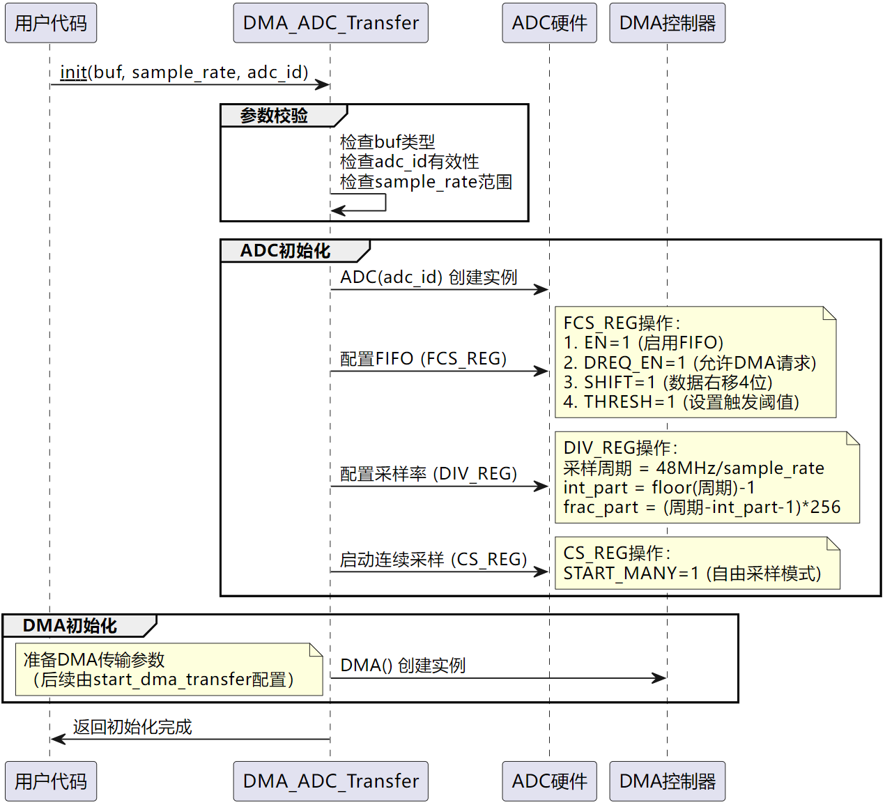
- Parameter validation: check buffer type is bytearray, validate adc_id ∈ {0,1,2}, verify minimum sample‑rate requirement (>1000 Hz).
- Configure ADC FIFO, sample rate and launch free‑running sampling by calling
configure_adc_fifo,configure_adc_sample_rate,start_adc_continuous,stop_dma_adc_fifo.
configure_adc_fifo, configure_adc_sample_rate, start_adc_continuous, stop_dma_adc_fifo work by direct register read‑write operations:
configure_adc_fifo() Enable ADC FIFO hardware for DMA cooperation.
- Enable FCS.EN bit (bit 0) to activate FIFO.
- Set DREQ_EN bit (bit 3) so FIFO asserts DMA handshake request.
- Set SHIFT bit (bit 1) for 4‑bit right‑shift, reducing native 12‑bit ADC output to 8‑byte value for DMA byte transfers.
- Set THRESH field (bits 24‑31) to FIFO_THRESH = 1, DMA triggers when one sample is present inside FIFO.
configure_adc_sample_rate() Program ADC sampling frequency via DIV_REG clock divider.
- ADC reference clock = 48 MHz.
- Sample period =
48_000_000 / sample_rate. - Divider value = sample period − 1, split into integer‑part high‑byte and fractional‑part low‑byte.
- Write integer part to upper 8‑bits, fractional part to lower 8‑bits of DIV_REG.
start_adc_continuous() Start free‑running ADC sampling.
- Set START_MANY bit (bit 3) inside CS_REG.
- ADC continuously performs conversions at programmed sample rate without software intervention.
stop_dma_adc_fifo() Safely terminate ADC and DMA operations.
- Clear START_MANY bit inside CS_REG register to stop new conversions.
- Poll READY bit (bit 8) until final conversion finishes.
- DMA automatically halts once ADC stops asserting DREQ handshake signal.
start_dma_transfer implements DMA data‑movement:
def start_dma_transfer(self, wait_func = None, complete_callback = None, blocking = True):
    """
    Launch DMA transfer
    :param wait_func: Callback function invoked while waiting for DMA completion
    :param complete_callback: Callback function invoked on DMA completion
    :return: None
    """
    if blocking == False and wait_func is not None:
        raise ValueError("wait_func must be None when blocking is False")
    if complete_callback is not None:
        self.dma.irq(handler=complete_callback, hard=True)
    ctrl = self.dma.pack_ctrl(
        enable=True,
        size=0,
        inc_read=False,
        inc_write=True,
        treq_sel=DMA_ADC_Transfer.DREQ_ADC,
        irq_quiet = False
    )
    self.dma.config(
        read=self.FIFO_REG,
        write=addressof(self.buf),
        count=len(self.buf),
        ctrl=ctrl,
        trigger=False
    )
    self.dma.active(1)
    if blocking == True:
        while self.dma.active():
            if wait_func is not None:
                wait_func()
    else:
        return
Workflow:
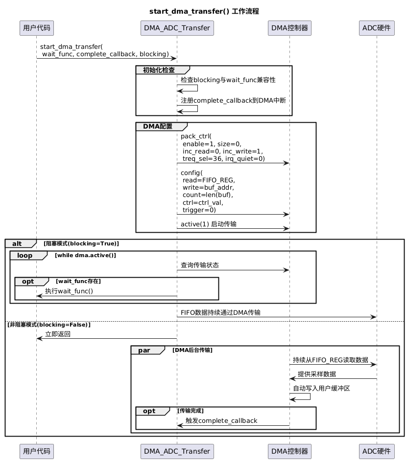
- Input validation: reject wait_func under non‑blocking mode. Register DMA IRQ handler if complete_callback is provided.
- Configure DMA control register: enable channel, 8‑bit transfer width, fixed read‑address pointing to ADC FIFO, auto‑increment destination‑buffer address, use ADC DREQ as hardware trigger, generate interrupt on every completed transfer.
- Set DMA source = ADC FIFO register physical address, destination = user buffer physical address, transfer count = buffer length, manual‑trigger mode.
- Evaluate blocking flag: if blocking=True, loop and invoke wait_func callback while DMA remains busy.
- Experiment Sample Code
Source code can be found inside resource‑package path elegance‑devkit v1\Demo\68 DMA_PeripheralToMemory.
Test program for DMA_ADC_Transfer class:
# Python env   : MicroPython v1.23.0
# -*- coding: utf-8 -*-
# @Time    : 2024/9/8 11:04 AM
# @Author  : Li Qingshui
# @File    : main.py
# @Description : DMA experiment, peripheral‑to‑memory: DMA transfers ADC FIFO samples into RAM
# ======================================== Import related modules =========================================
# Import time‑related modules
import time
# Import custom ADC DMA‑transfer class
from dma_adc_trans import DMA_ADC_Transfer
# Import custom UART‑TX DMA‑transfer class
from dma_uart_tx import DMA_UART_Tx
# Import MicroPython system modules
import micropython
# Import hardware‑related modules
from machine import Timer
# ======================================== Global variables ============================================
# Data buffer: 256 elements, each element 8‑bit 1‑byte
buf1 = bytearray(256)
# Second ADC sample buffer
buf2 = bytearray(256)
# Elapsed‑time variable for UART DMA transmission
uart_dma_time = 0
# Elapsed‑time variable for ADC DMA acquisition
adc_dma_time = 0
# Completion flag for instance‑1 ADC‑DMA plus UART‑DMA workflow
dma_1_adc_complete_flag = False
# Completion flag for instance‑2 ADC‑DMA plus UART‑DMA workflow
dma_2_adc_complete_flag = False
# ======================================== Function definitions ============================================
def adc_wait_dma_complete() -> None:
    """
    Callback invoked while waiting for ADC‑DMA transfer finish.
    Args:
        None
    Returns:
        None
    """
    print("DMA‑ADC transmitting ADC data")

def adc_dma_complete_callback(d: object) -> None:
    """
    Callback invoked when ADC‑DMA transfer completes.
    Args:
        d (object): DMA‑channel instance object.
    Returns:
        None
    """
    print("DMA‑ADC transfer complete")

def uart_dma_trans_buf1_isr(d: object) -> None:
    """
    Interrupt‑service‑routine: schedule post‑transfer callback for buf1 workflow.
    Args:
        d (object): DMA‑channel instance object.
    Returns:
        None
    """
    micropython.schedule(uart_dma_trans_buf1, d)

def uart_dma_trans_buf1(d: object) -> None:
    """
    DMA‑UART transmit workflow for buf1.
    Args:
        d (object): DMA‑channel instance object.
    Returns:
        None
    """
    global dma_uart, buf1, dma_1_adc_complete_flag
    while d.active():
        pass
    dma_uart.dma_transmit(buf=buf1, blocking=False)
    dma_1_adc_complete_flag = True

def uart_dma_trans_buf2_isr(d: object) -> None:
    """
    Interrupt‑service‑routine: schedule post‑transfer callback for buf2 workflow.
    Args:
        d (object): DMA‑channel instance object.
    Returns:
        None
    """
    micropython.schedule(uart_dma_trans_buf2, d)

def uart_dma_trans_buf2(d: object) -> None:
    """
    DMA‑UART transmit workflow for buf2.
    Args:
        d (object): DMA‑channel instance object.
    Returns:
        None
    """
    global dma_uart, buf2, dma_2_adc_complete_flag
    while d.active():
        pass
    dma_uart.dma_transmit(buf=buf2, blocking=False)
    dma_2_adc_complete_flag = True

# def dma_timer_check(timer: Timer) -> None:
#     """
#     Timer interrupt callback for DMA‑transfer state polling.
#     If finished, launch DMA transfer for alternate buffer.
#
#     Args:
#         timer (machine.Timer): Triggering timer instance.
#
#     Returns:
#         None
#     """
#     global dma_adc_1, dma_adc_2, dma_1_adc_complete_flag, dma_2_adc_complete_flag
#
#     if dma_2_adc_complete_flag:
#         dma_adc_1.start_dma_transfer(blocking=False, complete_callback=uart_dma_trans_buf1_isr)
#         dma_2_adc_complete_flag = False
#
#     if dma_1_adc_complete_flag:
#         dma_adc_2.start_dma_transfer(blocking=False, complete_callback=uart_dma_trans_buf2_isr)
#         dma_1_adc_complete_flag = False

# ======================================== Custom classes ============================================
# ======================================== Initialization ==========================================
time.sleep(3)
print("FreakStudio: DMA Peripheral to Memory Test")
# Instantiate DMA_ADC_Transfer object with sample buffer
dma_adc = DMA_ADC_Transfer(buf = buf1, sample_rate = 2000, adc_id = 0)
# Instantiate DMA‑UART‑TX object: UART0, baudrate 115200, TX=GP0, RX=GP1
dma_uart = DMA_UART_Tx(uart_num=0, baudrate=115200, tx_pin=0, rx_pin=1)
# ======================================== Main program ===========================================
start_time = time.ticks_us()
# Launch blocking‑mode DMA acquisition
dma_adc.start_dma_transfer(wait_func = adc_wait_dma_complete,
                           complete_callback = adc_dma_complete_callback,
                           blocking = True)
end_time = time.ticks_us()
dma_adc.close()
adc_dma_time = time.ticks_diff(end_time, start_time) / 1000
print("DMA run time: {:.2f} ms".format(adc_dma_time))

print("FreakStudio: Start DMA UART transmit")
uart_dma_time = dma_uart.dma_transmit(buf=buf1,blocking=True) / 1000
print("DMA UART Finished,run time: {:.2f} ms".format(uart_dma_time))

# Two‑buffer ping‑pong acquisition
dma_adc_1 = DMA_ADC_Transfer(buf=buf1, sample_rate=2000, adc_id=0)
dma_adc_2 = DMA_ADC_Transfer(buf=buf2, sample_rate=2000, adc_id=0)
# Start first DMA‑ADC transfer in non‑blocking mode
dma_adc_1.start_dma_transfer(blocking=False,complete_callback = uart_dma_trans_buf1_isr)

# dma_check_timer = Timer(-1)
# dma_check_timer.init(period=10, mode=Timer.PERIODIC, callback=dma_timer_check)

while True:
    start_time = time.ticks_us()
    if dma_2_adc_complete_flag == True:
        dma_adc_1.start_dma_transfer(blocking=False,complete_callback = uart_dma_trans_buf1_isr)
        dma_2_adc_complete_flag = False
    if dma_1_adc_complete_flag == True:
        dma_adc_2.start_dma_transfer(blocking=False,complete_callback = uart_dma_trans_buf2_isr)
        dma_1_adc_complete_flag = False
    end_time = time.ticks_us()
    dma_time = time.ticks_diff(end_time, start_time) / 1000
    print("DMA ADC run time: {:.2f} ms".format(dma_time))
Program workflow:
- Execute blocking‑mode
dma_adc.start_dma_transfer(), measure and print ADC‑DMA elapsed time after completion. - Call
dma_uart.dma_transmit(buf1, blocking=True)for DMA‑UART transmission, measure and print UART‑DMA elapsed time. - Ping‑pong double‑buffer DMA sampling and transmission: create two instances
dma_adc_1anddma_adc_2bound tobuf1andbuf2. Startdma_adc_1withuart_dma_trans_buf1_isrcompletion callback. - Main‑loop polling logic:
- If
dma_2_adc_complete_flag == True, startdma_adc_1and clear flag. - If
dma_1_adc_complete_flag == True, startdma_adc_2and clear flag.
- If
Overall timing diagram for demo program:
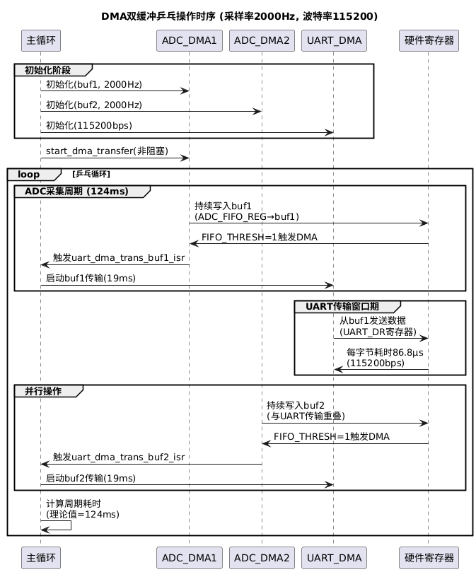
Core logic: DMA moves ADC samples from peripheral FIFO into RAM, second DMA channel streams buffer contents out over UART. Ping‑pong double‑buffering achieves continuous acquisition and transmission.
With sample‑rate=2000 Hz, UART baudrate=115200, buffer length=256 bytes: UART‑DMA transfer consumes ~19 ms, ADC‑DMA transfer consumes ~124 ms. Two buffers buf1 / buf2 take turns storing incoming ADC samples. While one buffer fills with new ADC data, the other finished buffer can be transmitted over serial. This avoids conflict between acquisition and data‑processing, reduces latency and improves throughput.
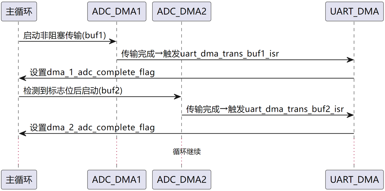
Initialize two sample buffers:
# Data buffer: 256 elements, each element 8‑bit 1‑byte
buf1 = bytearray(256)
# Second ADC sample buffer
buf2 = bytearray(256)
Instantiate two DMA_ADC_Transfer objects:
# Create instance‑1 bound to buf1
dma_adc_1 = DMA_ADC_Transfer(buf=buf1, sample_rate=2000, adc_id=0)
# Create instance‑2 bound to buf2
dma_adc_2 = DMA_ADC_Transfer(buf=buf2, sample_rate=2000, adc_id=0)
Launch DMA‑ADC transfer for dma_adc_1:
# Start dma_adc_1 in non‑blocking mode
dma_adc_1.start_dma_transfer(blocking=False,complete_callback = uart_dma_trans_buf1_isr)
uart_dma_trans_buf1_isr is interrupt‑service routine scheduled on DMA completion. It schedules subsequent processing logic and raises completion flag:
def uart_dma_trans_buf1_isr(d: object) -> None:
    """
    Interrupt‑service‑routine: schedule post‑transfer callback for buf1 workflow.
    Args:
        d (object): DMA‑channel instance object.
    Returns:
        None
    """
    micropython.schedule(uart_dma_trans_buf1, d)

def uart_dma_trans_buf1(d: object) -> None:
    """
    DMA‑UART transmit workflow for buf1.
    Args:
        d (object): DMA‑channel instance object.
    Returns:
        None
    """
    global dma_uart, buf1, dma_1_adc_complete_flag
    while d.active():
        pass
    dma_uart.dma_transmit(buf=buf1, blocking=False)
    dma_1_adc_complete_flag = True
Main‑loop polls completion flags to trigger next DMA job:
# Ping‑pong loop for continuous acquisition
while True:
    start_time = time.ticks_us()
    if dma_2_adc_complete_flag == True:
        dma_adc_1.start_dma_transfer(blocking=False,complete_callback = uart_dma_trans_buf1_isr)
        dma_2_adc_complete_flag = False
    if dma_1_adc_complete_flag == True:
        dma_adc_2.start_dma_transfer(blocking=False,complete_callback = uart_dma_trans_buf2_isr)
        dma_1_adc_complete_flag = False
    end_time = time.ticks_us()
    dma_time = time.ticks_diff(end_time, start_time) / 1000
    print("DMA ADC run time: {:.2f} ms".format(dma_time))
Alternative implementation: move polling logic into hardware timer interrupt to lower CPU load:
def dma_timer_check(timer: Timer) -> None:
    """
    Timer interrupt callback for DMA‑transfer state polling.
    If finished, launch DMA transfer for alternate buffer.
    Args:
        timer (machine.Timer): Triggering timer instance.
    Returns:
        None
    """
    global dma_adc_1, dma_adc_2, dma_1_adc_complete_flag, dma_2_adc_complete_flag
    if dma_2_adc_complete_flag:
        dma_adc_1.start_dma_transfer(blocking=False, complete_callback=uart_dma_trans_buf1_isr)
        dma_2_adc_complete_flag = False
    if dma_1_adc_complete_flag:
        dma_adc_2.start_dma_transfer(blocking=False, complete_callback=uart_dma_trans_buf2_isr)
        dma_1_adc_complete_flag = False

# Initialize software timer
dma_check_timer = Timer(-1)
# Fire dma_timer_check callback every 10 ms
dma_check_timer.init(period=10, mode=Timer.PERIODIC, callback=dma_timer_check)
Open SerialPlot software and select PC COM port connected to Pico board.
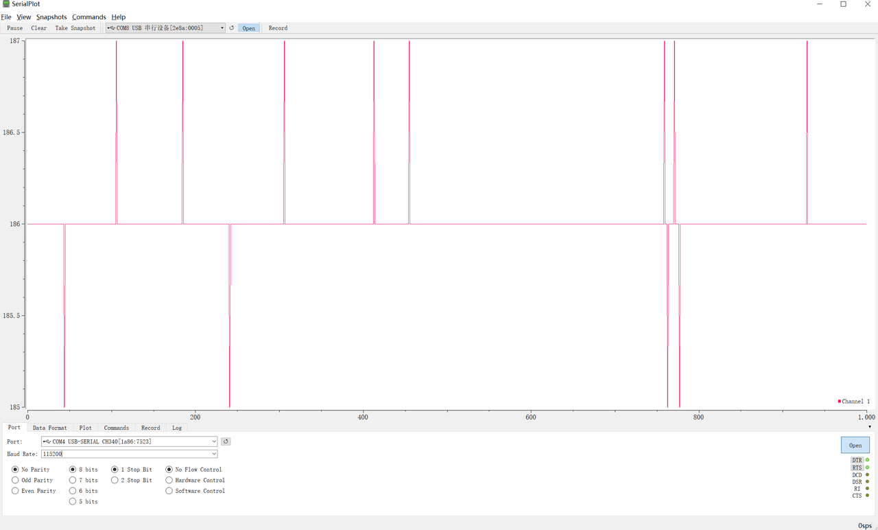
Data‑format configuration:

Flash firmware and open serial terminal:
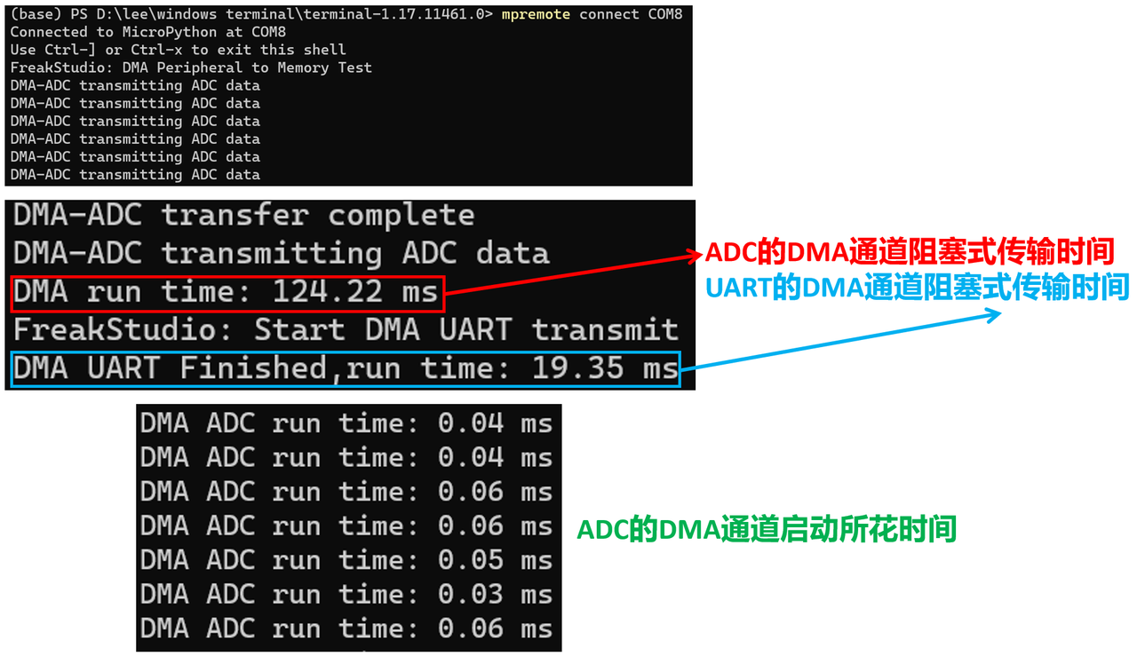
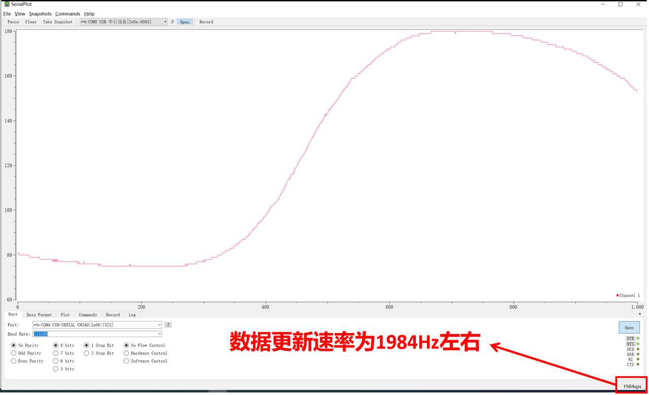
When using DMA plus double‑buffering for ADC‑to‑UART streaming, CPU overhead is minimal (~0.05 ms). SerialPlot shows effective sample rate around 2000 Hz.
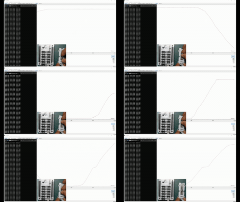
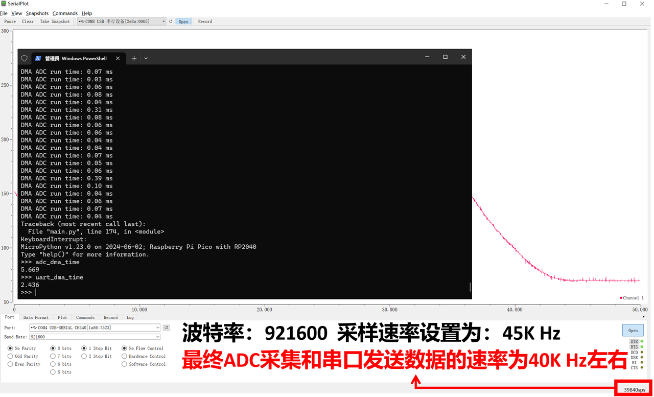
Test at baudrate=921600, ADC sample‑rate=45 kHz: practical throughput reaches ~40 kHz, limited by DMA latency and UART transmission overhead.
For higher throughput requirements: raise ADC sample‑rate and UART baud‑rate, increase buffer size. Larger buffers reduce processing‑event frequency and cut software overhead for high‑throughput use‑cases.