



Ethernet Illustrated: Encoding, MAC & CSMA/CD Explained
It introduces Ethernet encoding schemes, MAC access modes and the CSMA/CD mechanism.
Ethernet Coding
Ethernet Coding plays a vital role in Ethernet communication. It ensures reliable data transmission over physical media and accurate decoding on the receiving side. Ethernet adopts different coding technologies according to standards and transmission rates. Common Ethernet coding schemes are shown below:
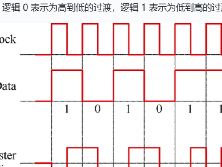
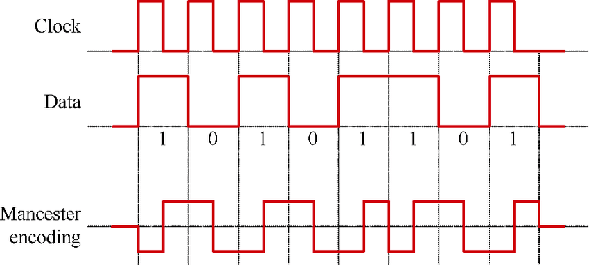
10BASE‑T Ethernet Uses Manchester coding. Every bit features a transition in the middle of the clock cycle. Logic 0 is represented by high‑to‑low transition, and logic 1 is represented by low‑to‑high transition.
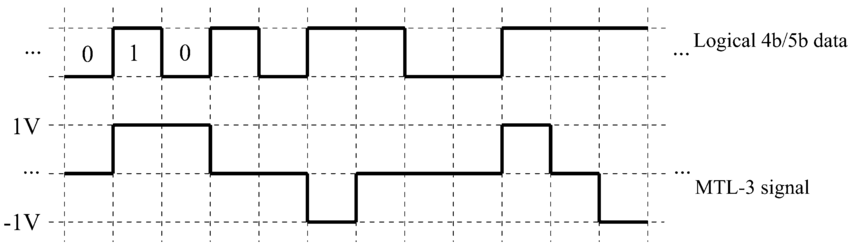
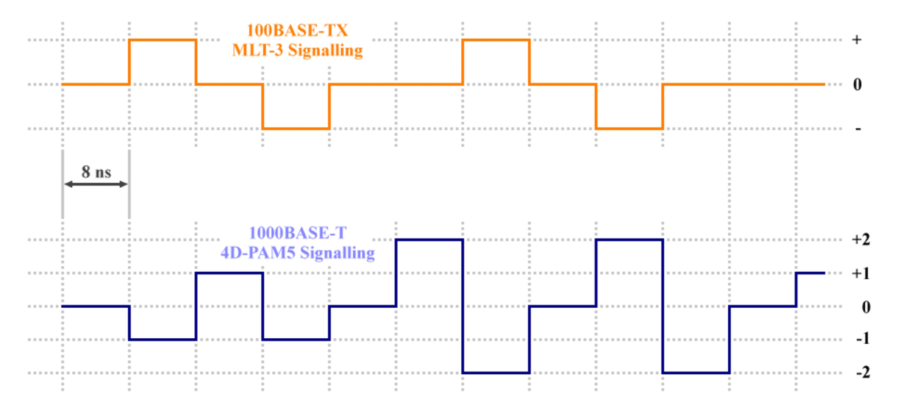
100BASE‑TX Ethernet Uses 4B/5B coding, which encodes 4‑bit data into 5‑bit codewords to guarantee sufficient transitions inside each codeword. The 5‑bit codewords are further transmitted via MLT‑3 (Multi‑Level Transition, 3‑level) signaling.
1000BASE‑T Ethernet Uses 4D‑PAM5 coding. It employs four twisted‑pair cables and applies 5‑level Pulse‑Amplitude Modulation (PAM5) on each pair. Data is transmitted across all four pairs simultaneously. Each wire pair carries 2 bits of data, delivering 8 bits per symbol in total.
- Deterministic MAC and Non‑Deterministic MAC
Within the MAC (Media Access Control) sublayer, media‑access‑control methods fall into two major categories: Deterministic and Non‑deterministic. They mainly differ in data‑transmission timing and scheduling strategies.
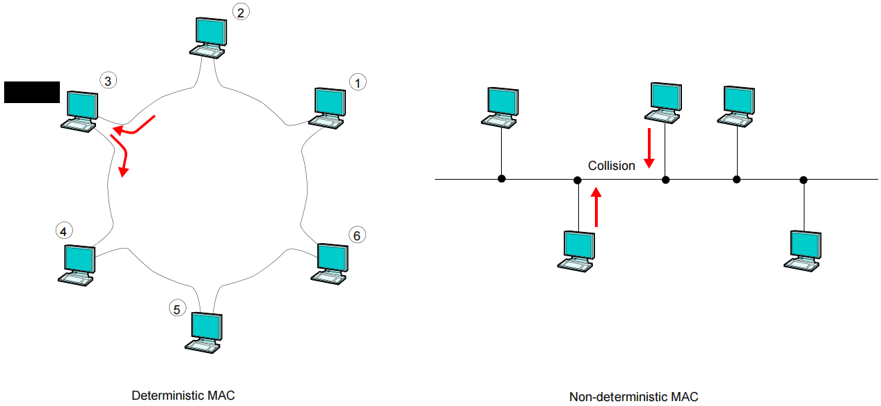
Deterministic MAC method It guarantees deterministic transmission timing, meaning each device gains network‑access opportunities within assigned time slots. It fits scenarios requiring strict timing control such as industrial‑control systems and real‑time communication systems. Token Ring or Time‑Division Multiple Access can implement deterministic MAC.
Non‑deterministic MAC method It offers no timing guarantee. Devices contend for network access, which may bring unpredictable transmission latency. It applies to general‑purpose data‑communication scenarios including Ethernet and wireless LAN. CSMA/CD or CSMA/CA can be adopted to resolve communication collisions among devices.
- CSMA/CD Carrier Sense Multiple Access with Collision Detection Mechanism
We explain the CSMA/CD mechanism taking Ethernet hub data sending‑receiving as an example. Back in the 1990s, Ethernet hubs were widely used to connect multiple computers (multiple nodes attached to one shared network bus, bus‑topology network). When data arrives at one hub port, the hub broadcasts the signal out of all other ports until the destination device receives it. Without CSMA/CD, simultaneous incoming data would trigger network collisions.
Both H1 and H2 send Ethernet frames. The hub repeats these frames to the port connected to H3. The two frames collide and both get discarded.
Half‑duplex transmission mode is introduced to mitigate this issue. Half‑duplex means devices cannot send and receive at the same time. When one computer is transmitting, others must wait. Devices may start transmission when the link appears idle. However, collisions can still happen if two devices judge the channel free and start transmitting simultaneously.
The CSMA/CD mechanism is designed to solve this problem. Key rules of CSMA/CD are as follows:
Carrier Sense Before sending data, the network adapter detects whether other devices are transmitting on the wire (detect carrier signal). If ongoing transmission is detected, the adapter defers its own transmission to avoid collisions.
Multiple Access Ethernet permits multiple devices to share the same physical cable for data transfer. Each device may transmit independently without central scheduling.
Collision Detection Collisions occur when two devices start sending at the same moment. After detecting a collision, devices stop transmission immediately and retry after a random time interval.
In short, CSMA/CD works as follows: On shared Ethernet links, devices sense channel status before transmission. If idle, they send frames and start a timer for collision monitoring. If the channel is busy, they wait for a random period then retry. If repeated attempts still result in collisions, transmission aborts and an error is reported.
In modern Ethernet, hubs have been replaced by switches. Switches connect devices over independent ports and support full‑duplex communication to eliminate collisions. Switches read Ethernet frames and forward frames only toward target devices. When a second frame arrives for one busy port, the switch queues the second frame to prevent collisions.