Ethernet Illustrated: Cables, T568, Wiring & RJ45 Indicators
It explains Ethernet cable types, T568 wiring standards and RJ45 indicator lights.
Transmission Medium
Common transmission media for Ethernet include the following types:
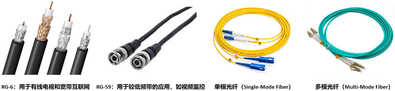
Coaxial Cable Composed of central conductor, insulating layer, braided metal shielding layer and outer insulating layer.
Twisted Pair Cable Two insulated copper wires twisted together to reduce interference and crosstalk.
Fiber Optic Cable Composed of fiber core, cladding and protective outer layer.
Differences among different types of twisted‑pair cables are shown below:
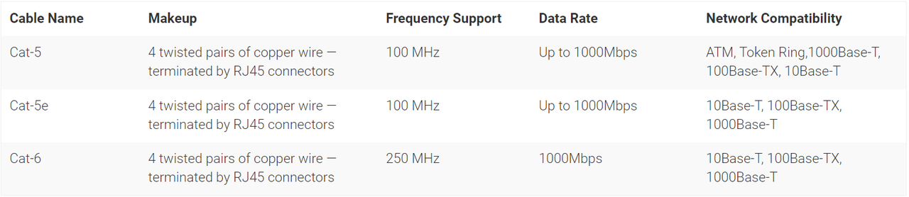
Only Category 5, Category 5e and Category 6 cables are compared here.
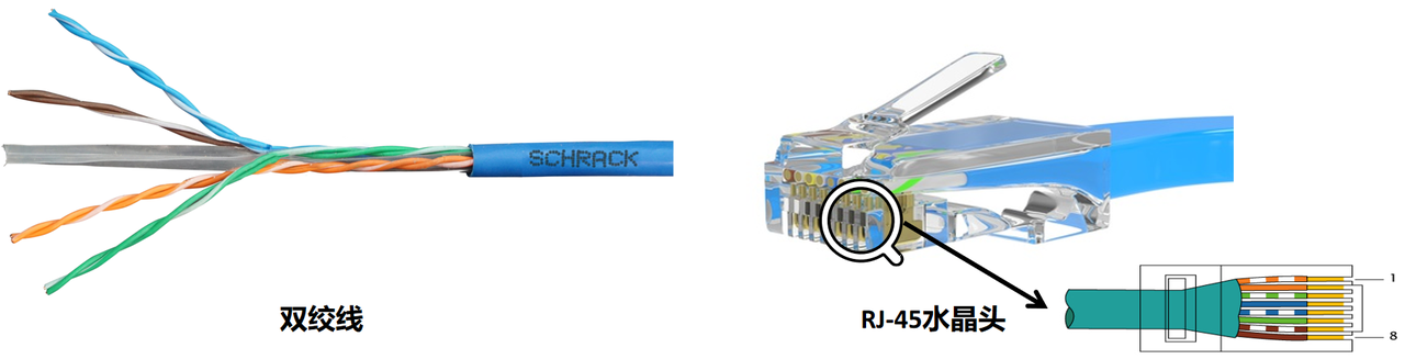
The most commonly‑used Ethernet cable is UTP cable. It consists of a length of unshielded twisted‑pair wire and RJ45 modular plug. Eight differently‑colored wires are grouped into four twisted pairs. Twisting wire pairs minimizes electromagnetic radiation and external electromagnetic interference.
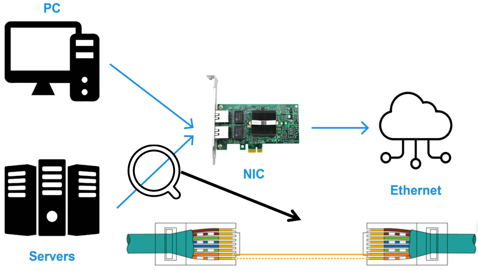
Different devices can build a data‑transmission loop by connecting their network ports with UTP cables or by connecting to the same switch.
An RJ45 connector has eight pins. Each pin serves a specific purpose under standard wiring schemes:
Tx+ Transmit Positive and Tx‑ Transmit Negative Positive and negative signal lines for data transmission.
Rx+ Receive Positive and Rx‑ Receive Negative Positive and negative signal lines for data reception.
Two widely‑accepted pin‑out standards are T568A and T568B.
T568A standard
Pin No.  Signal Name  Color
1        Tx+         White‑Green
2        Tx‑         Green
3        Rx+         White‑Orange
4        -           Blue
5        -           White‑Blue
6        Rx‑         Orange
7        -           White‑Brown
8        -           Brown
T568B standard
Pin No.  Signal Name  Color
1        Tx+         White‑Orange
2        Tx‑         Orange
3        Rx+         White‑Green
4        -           Blue
5        -           White‑Blue
6        Rx‑         Green
7        -           White‑Brown
8        -           Brown
There are two RJ45 cable‑wiring types:
Straight‑through Cable Both ends adopt identical pin‑out arrangement, either T568A or T568B. Used to connect dissimilar‑type devices, for example computer to switch.
Crossover Cable Two ends use different pin‑out arrangements, one end T568A and the other T568B. Used for connecting devices of the same type, such as computer‑to‑computer.
Gigabit full‑duplex Ethernet 1000BASE‑T works differently. It utilizes all four wire pairs, supporting simultaneous transmit and receive on every pair.

RJ45 connectors include two indicator lamps showing network signal and link status.
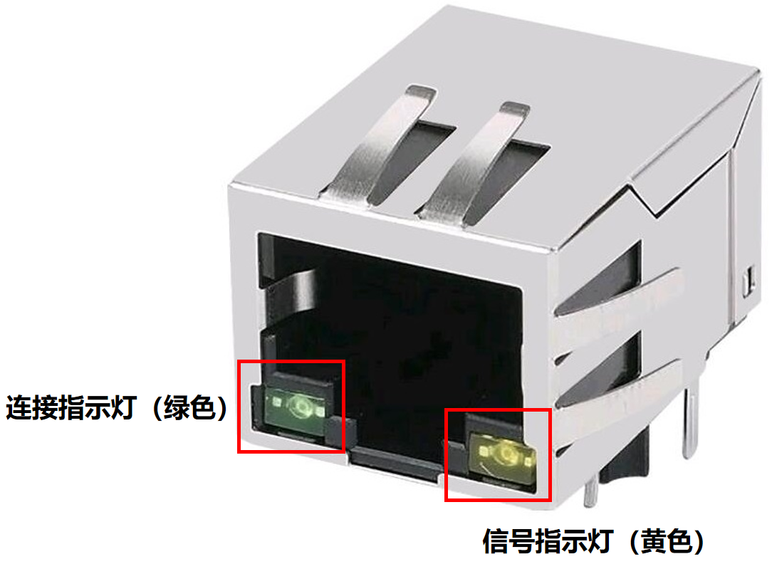
Indicator lamp definitions:
Link Light Green / Orange Lit lamp indicates normal physical link connection.
Activity Light Yellow / Green, valid only when link light is on Blinking activity light means normal ongoing data communication. Off activity light means no data traffic. Steady‑on activity light indicates short‑circuit on network cable.