Embedded Communication Basics: Transmission & Protocol Rules for Beginners
This tutorial explains embedded communication basics including transmission modes, duplex types, rate concepts, interfaces, buses and protocols.
COMPONENTS
PROJECT DESCRIPTION
【Preliminary Note】The original hardware example in this article was written based on the RP2040. The actual hardware used in this hands-on demonstration features the W55RP20 as the main controller chip. The circuit logic and UF2 flashing operation principles are universally applicable, with only the main controller model differing. The original chip model mentioned in the circuit descriptions below is provided for reference purposes only.
1. Classification and Concepts of Communication Modes
1.2 Classification by "Data Transmission Mode": Serial Communication vs. Parallel Communication
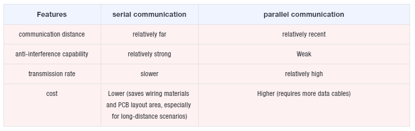
The data transmission mode determines how multiple data bits are transmitted simultaneously or in a time-sharing manner, and the two have markedly different characteristics:
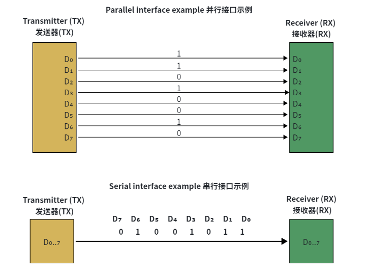
Schematic Diagram Comparing Data Transmission Modes of Parallel Interface and Serial Interface
Serial communication: A communication mode in which data is transmitted between devices via a small number of data signal lines (generally fewer than 8) bit by bit in the form of data bits, which is similar to a single-lane highway where only one data bit can be transmitted at a time.
Parallel communication: uses 8,16,32,64 or more data lines to transmit multiple data bits simultaneously (analogous to a multi-lane highway that can carry multiple data bits at the same time).
Since parallel transmission imposes extremely high requirements on the synchronization of multiple data lines, and the signal interference issue will significantly degrade performance as communication rate increases, high-speed serial differential transmission is increasingly adopted in high-rate scenarios (which achieves near-parallel high bandwidth via serial means).
1.3 Classification by "Data Synchronization Mode": Synchronous Communication vs Asynchronous Communication
The synchronization mode determines "how the transmitting and receiving parties maintain consistent data timing", and the core difference lies in whether it relies on "clock signal" for synchronization:
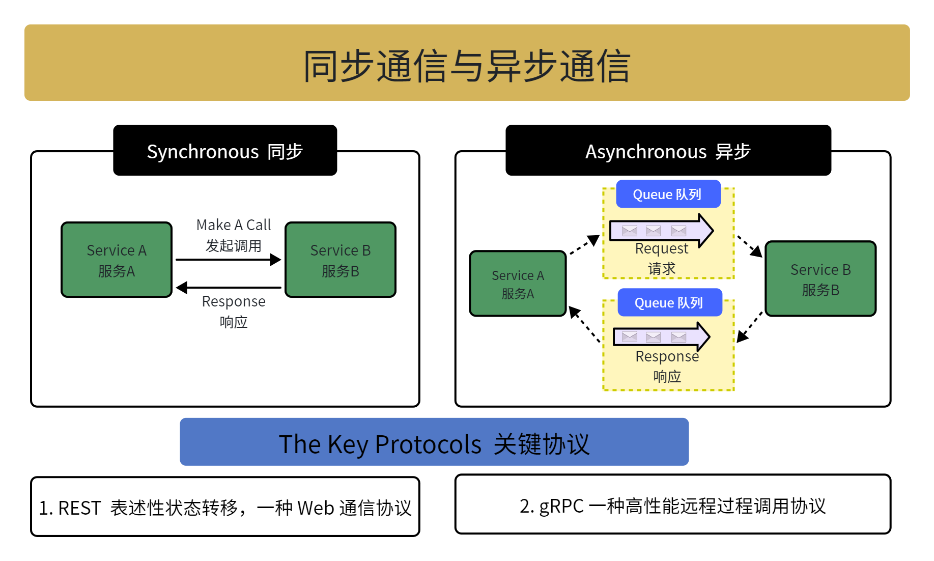
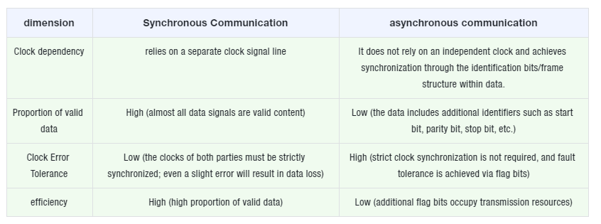
Schematic Diagram Comparing the Working Modes of Synchronous Communication and Asynchronous Communication
Synchronous Communication: The transmitting and receiving parties use a single clock signal line as a synchronization reference, and coordinate the synchronous data transmission under the drive of the "rising edge / falling edge" of the clock signal (in which "the vast majority of the data signals are valid data").
Asynchronous communication does not use a separate clock signal; instead, it inserts synchronization flag bits into the data signal (such as "start bit, parity bit, stop bit"), or transmits data in "packaged frames"; in some scenarios, both parties need to agree on a "transmission rate" to assist synchronization.
1.3 Classification by "Relationship between Transmission Direction and Time": Simplex, Half-duplex and Full-duplex Communication
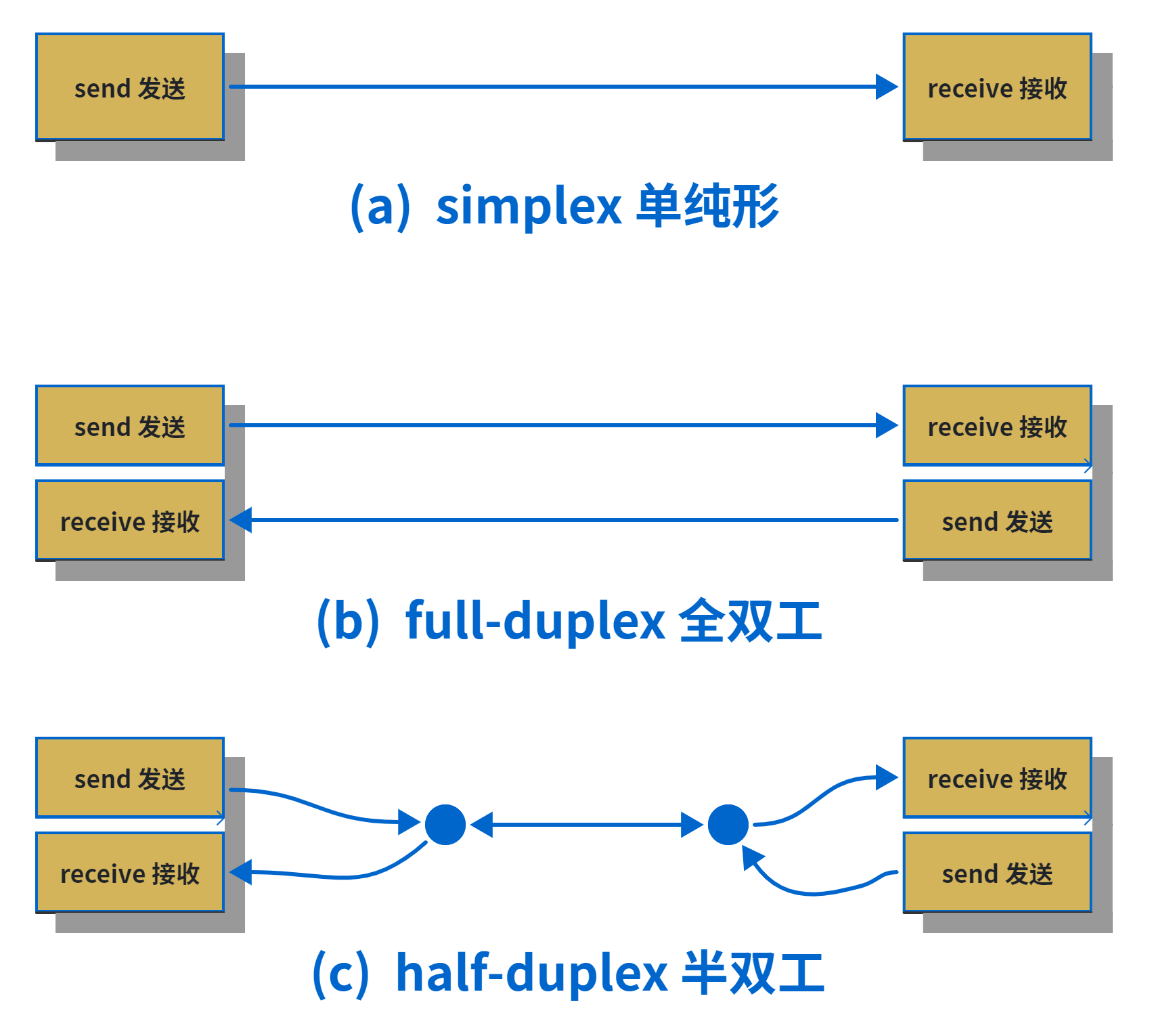
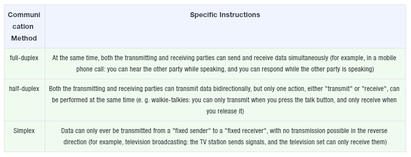
Schematic Diagram of Communication Transmission Mode
This dimension focuses on "the transmission direction of data in the channel (unidirectional / bidirectional)" and "whether simultaneous transmission and reception are possible in terms of time".
1.4 Core Concepts of Communication Rate: Bit Rate, Baud Rate, Symbol
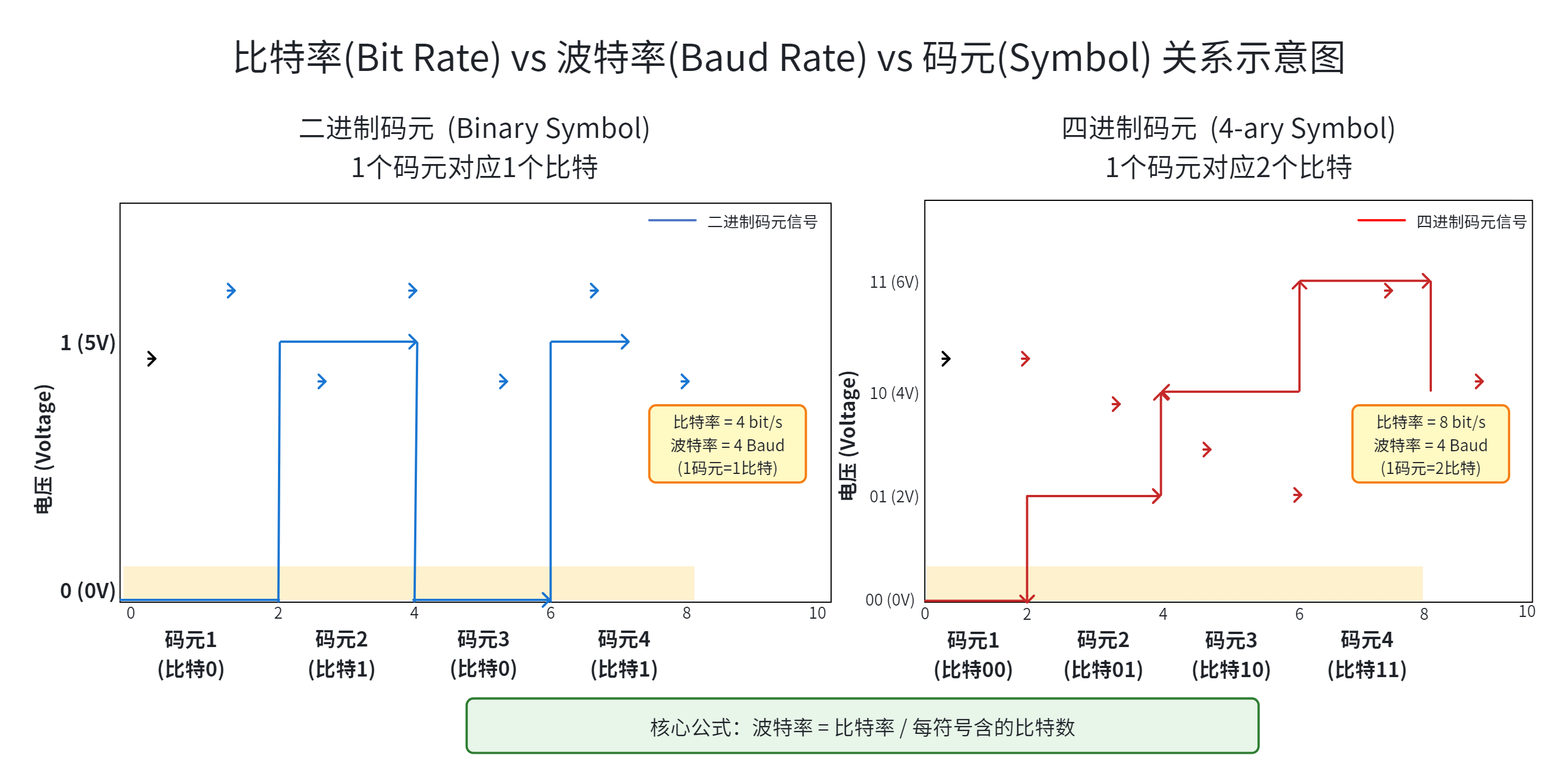
Correspondence diagram of bit rate and baud rate under different binary symbols
"Rate" measures the "transmission efficiency" of communication, and it is necessary to clarify the differences and connections among three key terms:
Bit rate: the number of binary bits transmitted per second, with the unit of "bits per second (bit/s)".
Baud rate: the number of symbols transmitted per second ("symbol" refers to the basic signal unit that carries information in digital communications).
Symbol: A symbol that represents binary digits using "signals with identical time intervals", and the "signal within this time interval" is the symbol. If the number of discrete states of a symbol is greater than 2 (e. g., M-ary), it is an M-ary symbol.
Binary symbol: If "0V represents 0 and 5V represents 1", a single symbol can only represent two states, either 0 or 1 (corresponding to 1 binary bit). In this case, baud rate = bit rate (since one symbol carries one bit).
Multi-level symbol: If "0V represents 00,2V represents 01,4V represents 10, and 6V represents 11", one symbol can represent four states: "00,01,10,11"(corresponding to 2 binary bits). In this case, baud rate = bit rate ÷ 2 (since one symbol carries 2 bits).
The Relationship Between Baud Rate and Bit Rate: Baud Rate = Bit Rate / Number of Bits Per Symbol.
2. Definitions and Relationships of Interface, Bus and Protocol
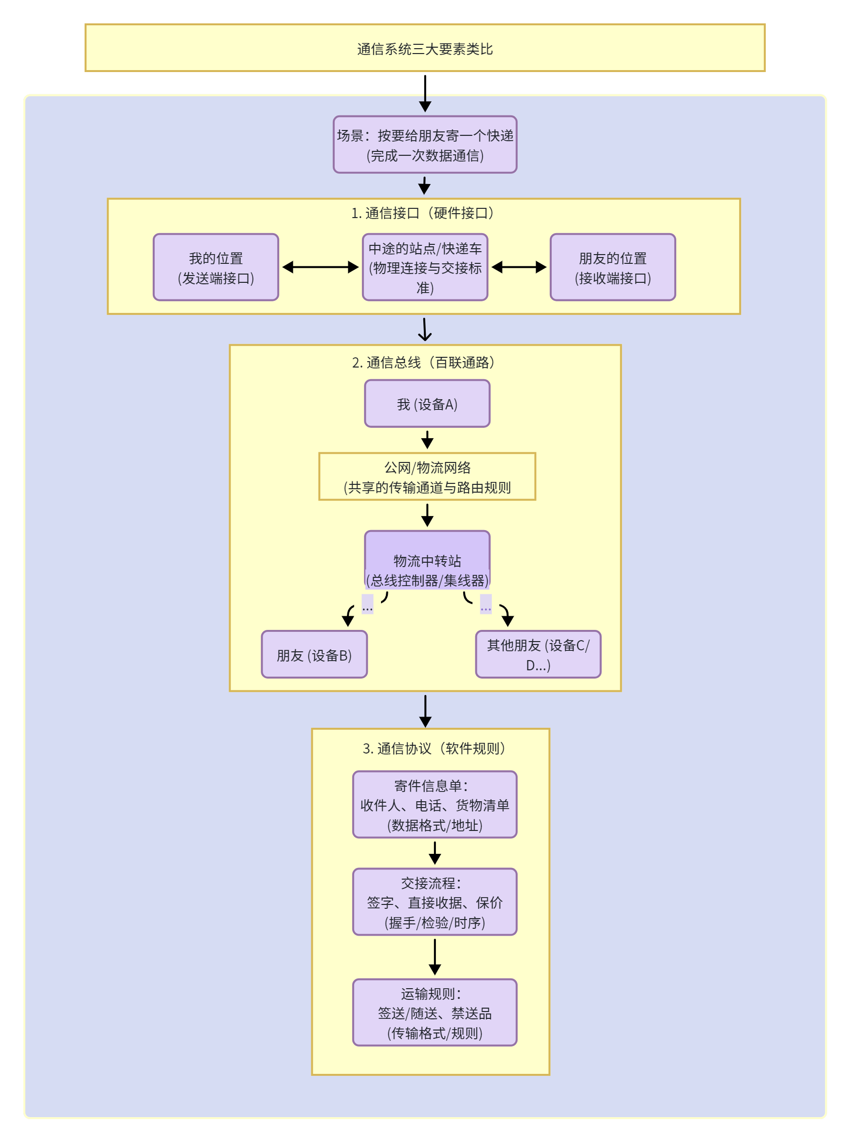
The core of a communication system lies in the combination of " hardware interconnection " and " software rules ". Communication interface (hardware interconnection standard), communication bus (interconnection pathway for multiple components), and Communication Protocol (data transmission rule) are the three core elements, whose definitions and interrelations are specified as follows:
Analogy Schematic Diagram of the Three Core Elements of Communication Systems
Communication interface: refers to the hardware connection standard for input/output, and a "hardware interface that implements communication functions" is exactly a communication interface. According to the "data transmission mode", communication is divided into serial communication (transmitting bit by bit in sequence) and parallel communication (transmitting multiple bits simultaneously), so communication interfaces also fall into two corresponding categories:
Serial Interface (Serial Port): A hardware interface that supports serial communication (such as the RS-232DB9 interface).
Parallel Interface (Parallel Port): A hardware interface that supports parallel communication (such as the parallel port on early printers).
Communication bus: It is a set of transmission channels, which consists of components such as "data lines, address lines, and control lines", serving as the "pathway" for data transmission between logic devices (e. g., chips, modules). In a broad sense, computer communication is categorized into serial and parallel communication according to its "transmission characteristics", and the corresponding buses are also divided into:
Serial bus: such as I2C, SPI, UART (universal asynchronous receiver/transmitter bus) and the like, which transmit data bit by bit.
Parallel bus: For example, the early PCI bus transmits multiple bits of data simultaneously.
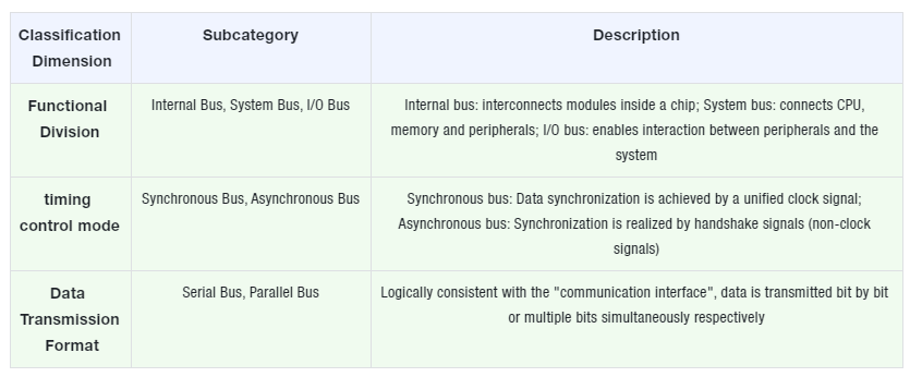
In addition, buses can also be classified from other dimensions (for more detailed scenario division):
Communication Protocol is a set of rules for data transmission, serving as an "overall collaboration framework" — it defines the interaction relationships between interface devices, components, electrical signals, buses, and transmission channels, ensuring that all components can cooperate to complete "signal transmission and data interaction".
The relationship among the three is summarized as follows:
Interface: It emphasizes " hardware connection between two components ", focusing on "conversion of signal form and data format"(e. g., "how to physically connect two devices").
Bus: It focuses more on " interconnection and expansion of multiple components ", emphasizing "scalability, flexibility, and industry standardization"(many buses follow unified standards, such as USB and PCIe).
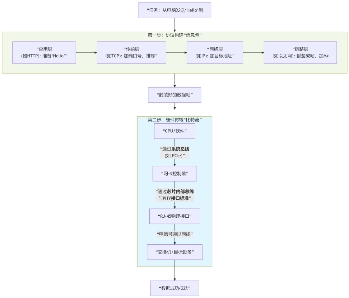
Protocol: it refers to the " software rules running on top of hardware (interfaces, buses)", which stipulates "how to use interfaces and how buses transmit data".
It should be noted that interfaces and buses are sometimes not strictly distinguished (often collectively referred to as "bus interface" or "interface bus"); a communication bus must match the corresponding Communication Protocol to enable communication (for example, the USB bus needs to comply with the USB protocol).