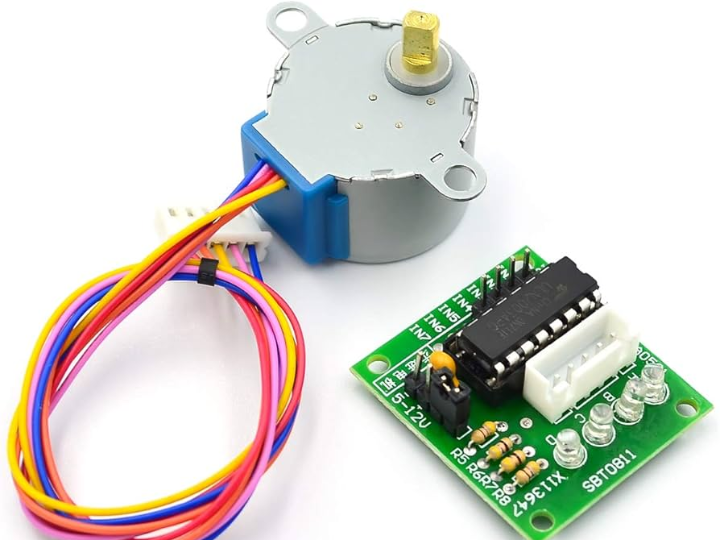
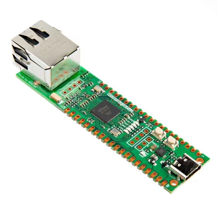
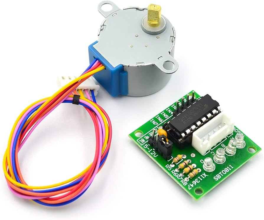
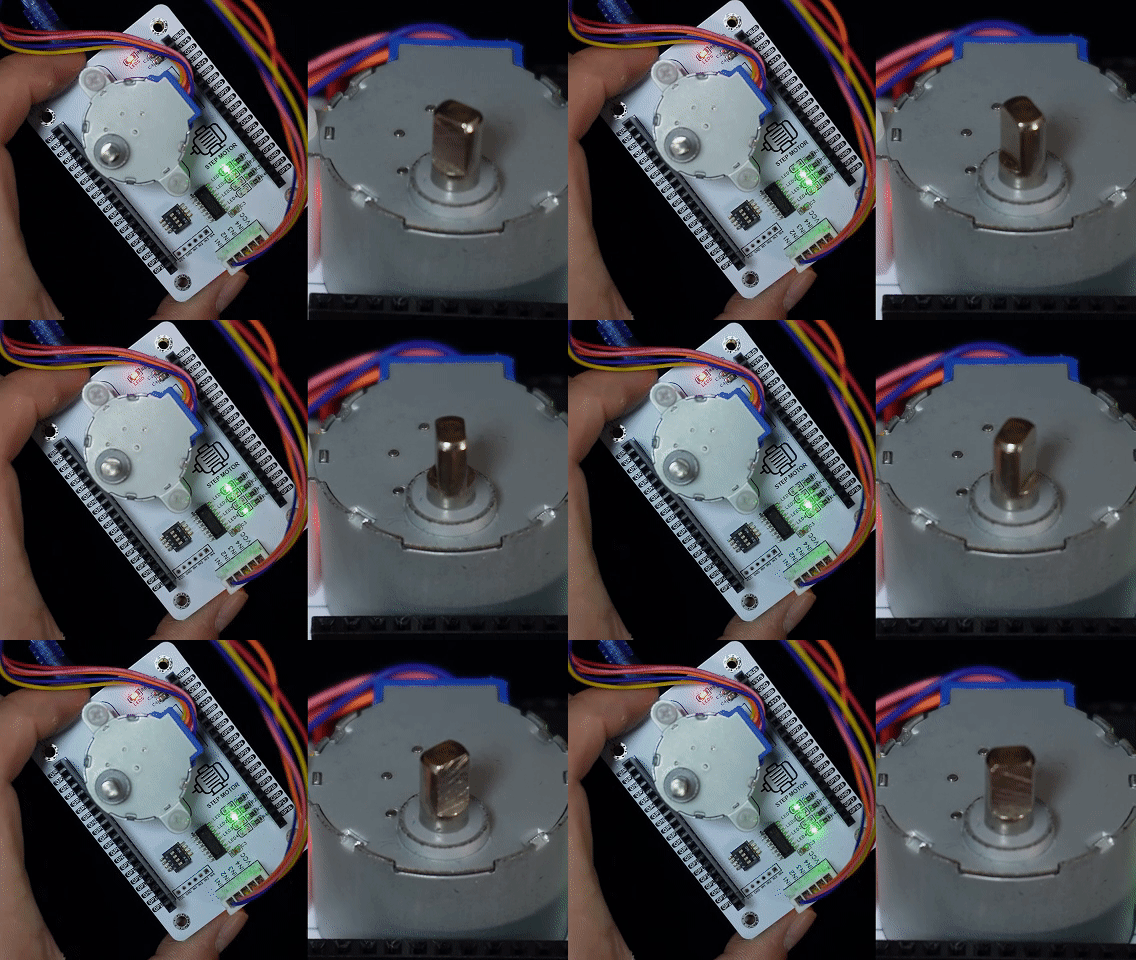
It introduces 28BYJ-48 stepper motor and ULN2003 driver, and demonstrates single-phase driving experiment on Fengya No.1 board via MicroPython GPIO control.
COMPONENTS
PROJECT DESCRIPTION
【Preliminary Note】The original hardware example in this article was written based on the RP2040. The actual hardware used in this hands-on demonstration features the W55RP20 as the main controller chip. The circuit logic and UF2 flashing operation principles are universally applicable, with only the main controller model differing. The original chip model mentioned in the circuit descriptions below is provided for reference purposes only.
1. Basic Knowledge of Stepper Motor
A stepper motor is a special type of electric motor that can convert input electrical pulse signals into discrete changes in angle or position, thereby achieving precise angle control. Stepper motors mainly have the following characteristics:
Stepping operation: A stepper motor controls the power-on sequence of its coils to drive the rotor to rotate at a fixed angle (step angle), thereby realizing position control. Common step angles include 1.8°, 0.9°, etc.
High positioning accuracy: The stepping motor can precisely control the rotation angle, with high positioning accuracy, generally within ±3%.
Open-loop control: The position control of a stepper motor is realized through open-loop control, which enables precise control without the need for feedback signals.
High torque: The stepper motor delivers a high output torque at low speeds, making it suitable for applications driving heavy loads.
Quick response: The stepping motor features fast start-up, stop and steering speeds, as well as rapid response.
Stepper motors are widely used in various automated equipment, such as printers, CNC machine tools, robots, 3D printers, etc. , making them an ideal choice for achieving precise position control. By controlling the frequency and sequence of pulse signals, the rotation speed, angle and direction of the motor can be accurately controlled.
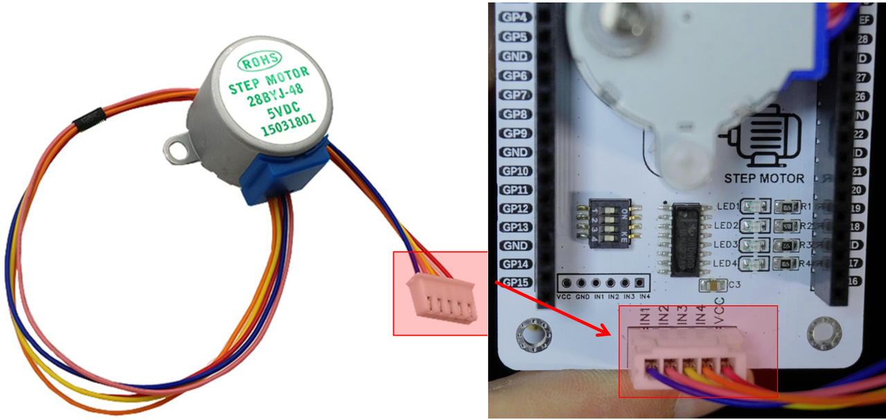
Here, the motor model we use is 28BYJ-48 five-wire four-phase stepper motor:
It has the following main features:
Small dial-type structure: The 28BYJ-48 is compact in size, with a diameter of only 28mm and a length of approximately 34mm, making it extremely space-saving.
Low-voltage power supply: The operating voltage ranges from 5V to 12V, which can be directly connected to low-voltage circuits such as microcontrollers.
Low power consumption: The typical operating current is only 12-14mA, which is extremely energy-efficient.
High torque: The output torque can reach up to 34.3 mN·m, which is sufficient to drive all kinds of small loads.
Low speed and high precision: the step angle is 0.0625°, with up to 4096 steps per revolution, delivering extremely high accuracy.
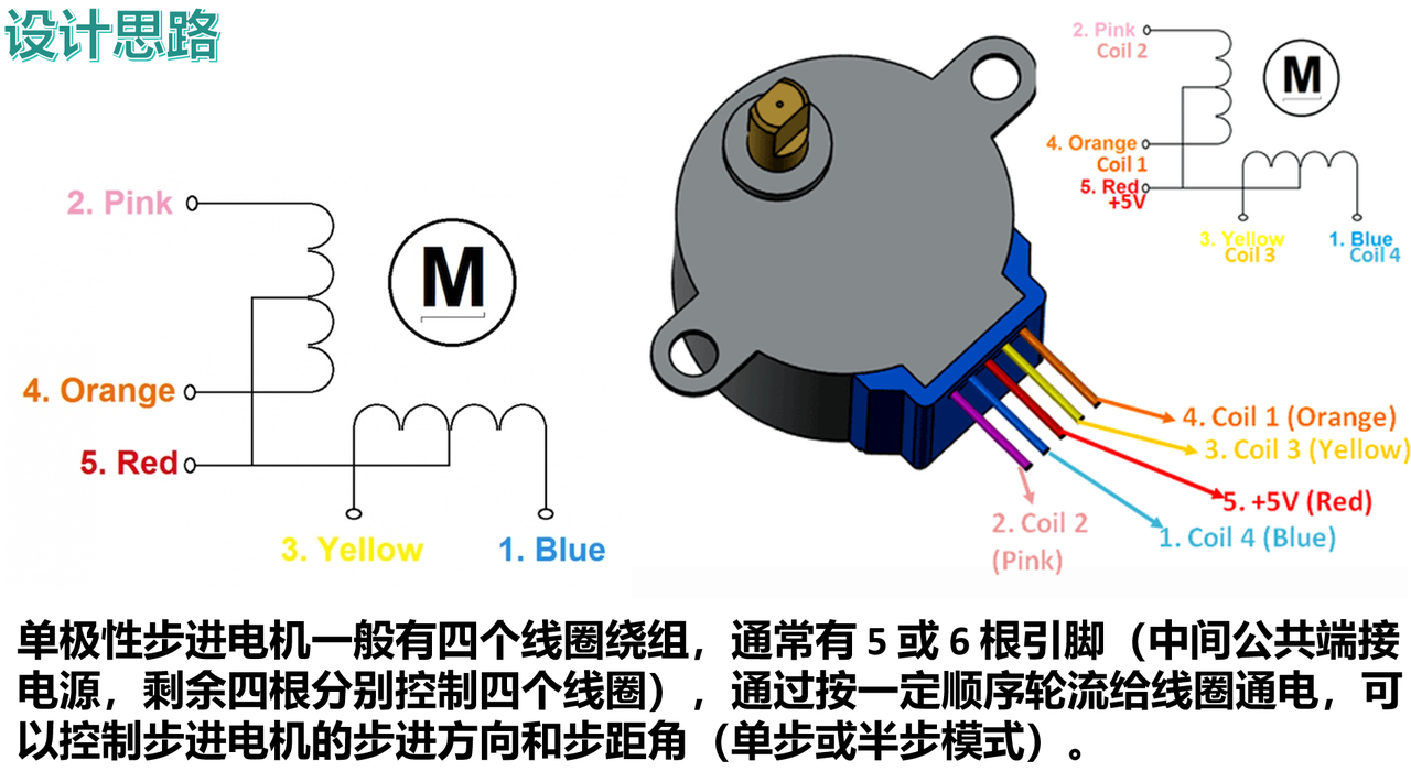
5 leads: including 4 wires for the two-phase winding and 1 common ground wire.
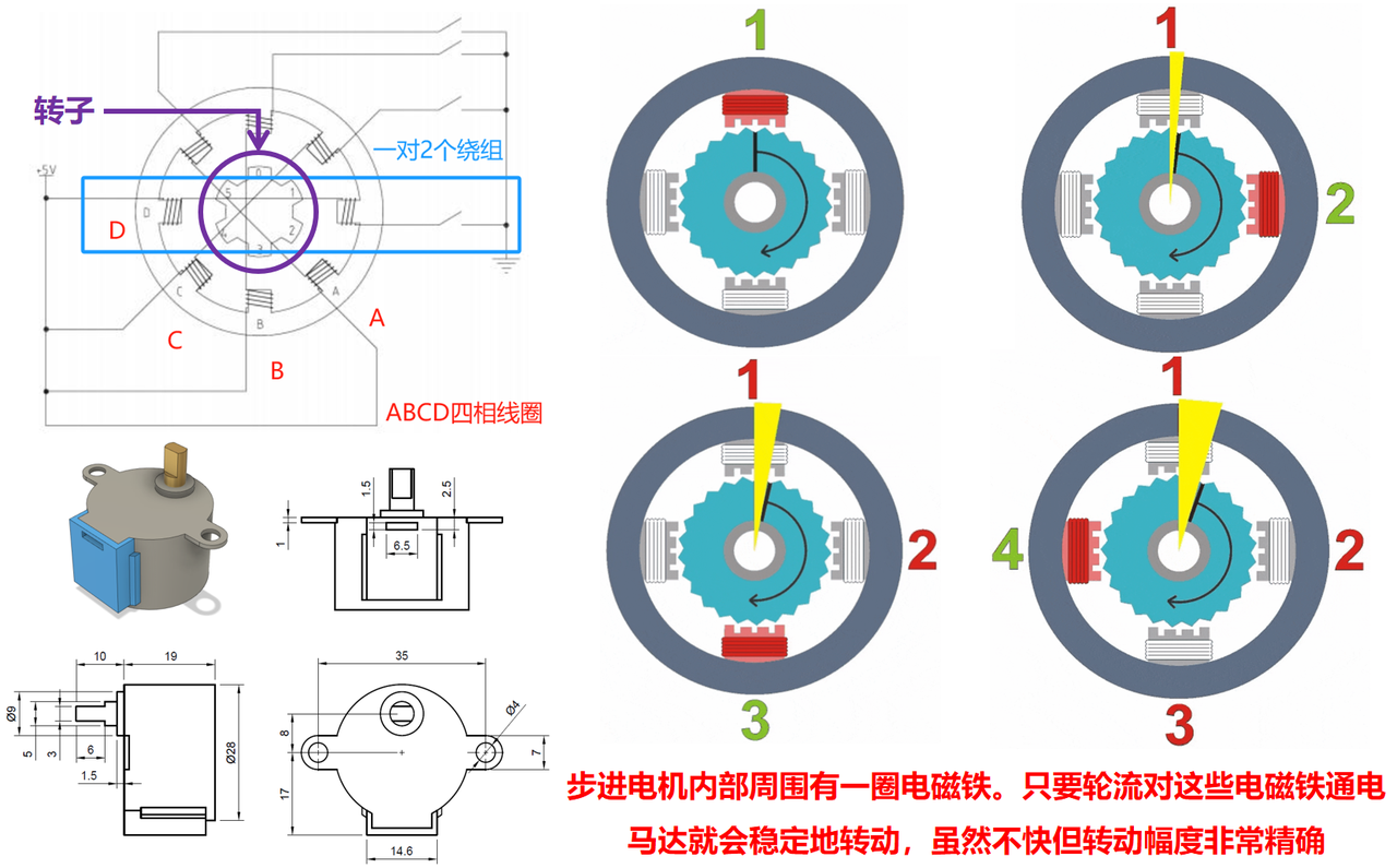
This 28BYJ-48 stepper motor is widely used in various small electromechanical devices, such as door locks, toys, automation equipment, etc. Thanks to its small size, low power consumption and sufficient torque, it is extremely suitable for use with microcontrollers. The working principle of the 28BYJ-48 5-wire 4-phase stepper motor can be briefly described as: by controlling the on-off of a total of 4 pairs (8 in total) of windings on the stator (the two windings directly opposite each other are always turned on or off simultaneously), the electromagnetic force generated when the windings are energized attracts the 6 teeth made of permanent magnet material on the rotor, so as to control the rotation of the intermediate rotor.
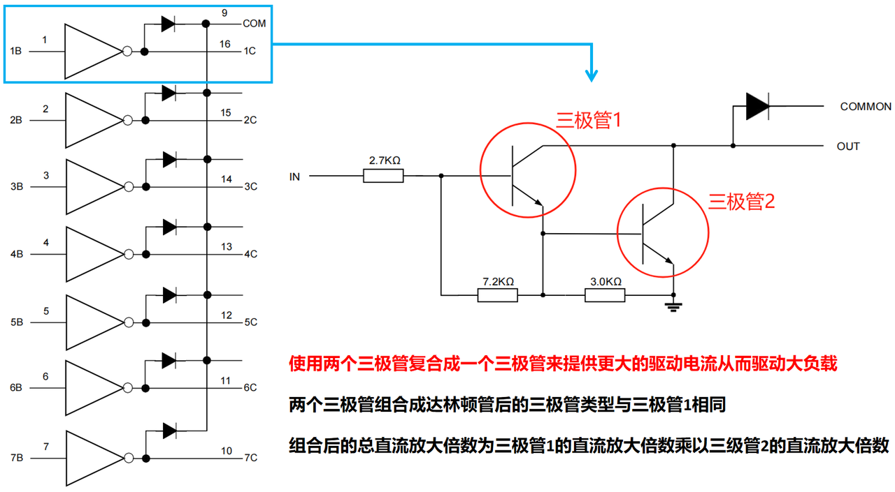
Here, when driving the 28BYJ-48 stepper motor, it is necessary to use the ULN2003 driver IC. The ULN2003 is a common 7-channel switch driver integrated circuit, and we can use the GPIO to drive the internal Darlington transistors (A Darlington transistor, also known as a composite transistor, is formed by combining two triodes into one to provide a larger driving current for driving heavy loads) to control their on-off, thereby realizing the control of high current for motor operation with low current output from the GPIO. It is mainly used to drive different types of electronic loads, such as stepper motors, relays, LEDs and other small electromagnetic devices.
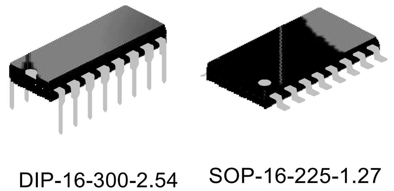
ULN2003 is available in two packages: DIP-16 through-hole and SOP-16 surface-mount.
The main control modes of stepping motors are as follows:
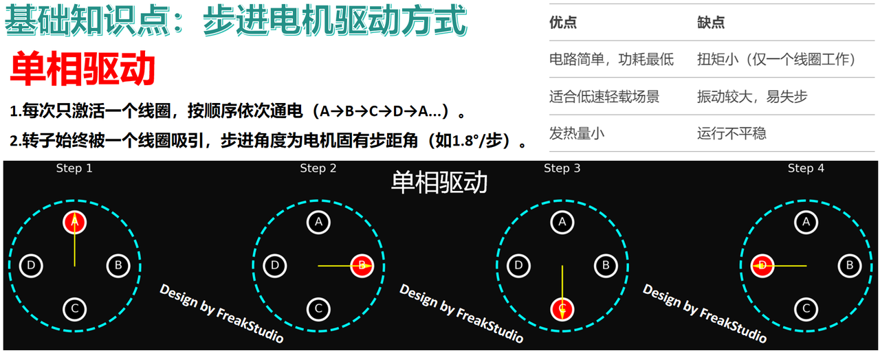
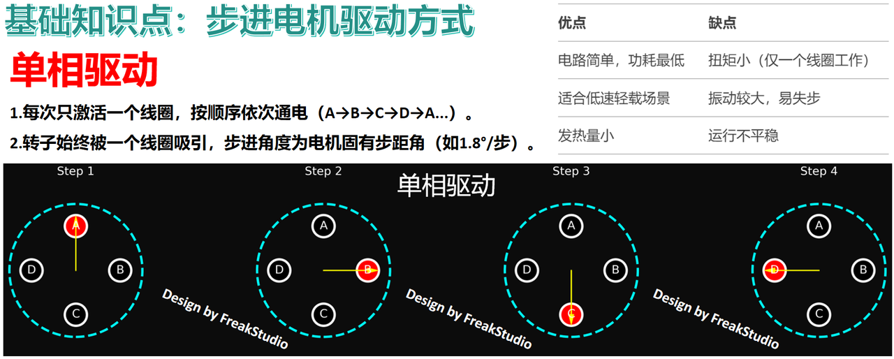
Single-phase drive: It controls the motor to rotate by only one step angle at a time (only one phase winding is energized in each operation), which is applicable to relatively simple motion control, yet features low precision and small torque.
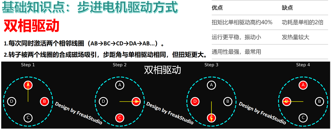
Two-phase drive: It only controls the motor to rotate by a half step angle at a time (two phases of windings are energized in each operation), which delivers relatively high torque but features slightly complex structure and control logic.
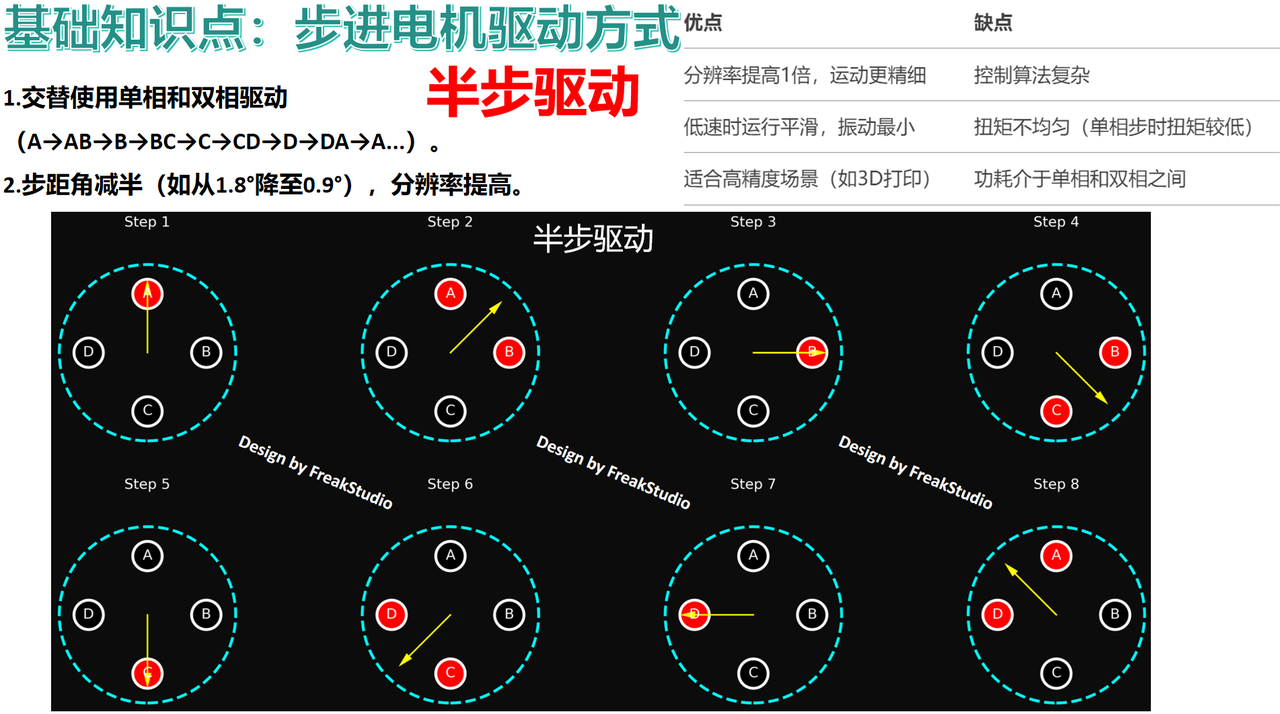
Half-step drive: It controls the motor to rotate by a half step angle each time (via the alternate power-on mode of single-phase and double-phase), so as to achieve higher control accuracy.
2. Application Experiment
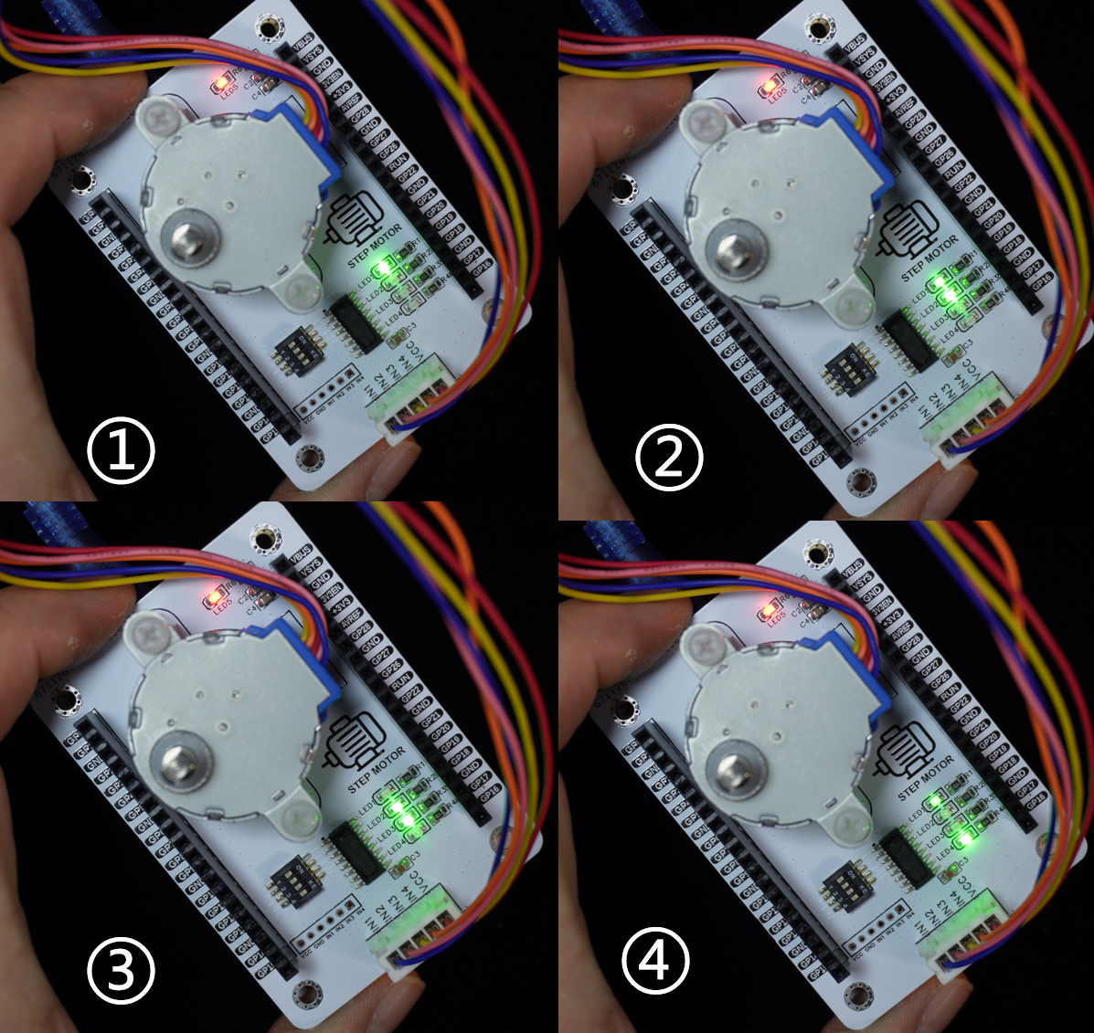
Here, we use the single-phase drive mode to drive the stepper motor. Simply put, the principle of the single-phase drive mode is as follows:
4-phase winding structure: The 28BYJ-48 stepper motor has 4 independent winding phases, which are controlled by the four pins IN1, IN2, IN3 and IN4 respectively.
Sequential power-on drive: By energizing these four phase windings in sequence, the stepper rotation of the rotor can be achieved. Each time the on-off state of one phase winding is switched, the rotor will move by one step angle.
Hysteresis Structure: The rotor adopts a hysteresis structure, that is, the rotor is composed of a ring of permanent magnets, while the stator consists of 4 electromagnet windings. When a certain phase winding of the stator is energized, a magnetic pole will be generated to attract or repel the magnetic pole of the rotor, thus driving the rotor to rotate.
Deceleration mechanism: The 28BYJ-48 has a built-in deceleration mechanism, which reduces the step angle from the motor's inherent 7.5° to 0.0625°, thus greatly improving the angular resolution.
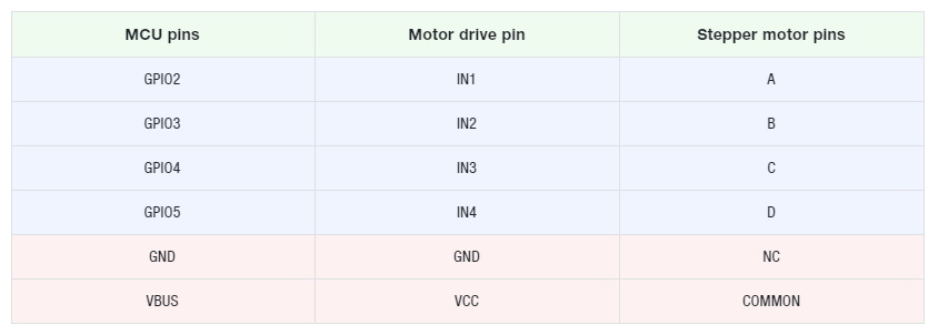
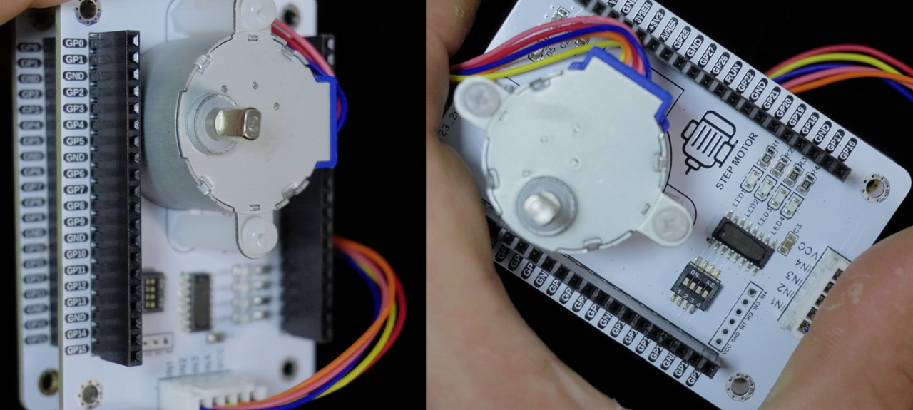
Here, we use the long pin headers on the Fuya-1 Board - Universal Compatibility Expansion Board to connect to the logic input interface section on the Fuya-1 Board - Stepper Motor Driver Board, and the pins used are shown in the table below:
Then connect the interface of the logic output section on the stepper motor driver board to the stepper motor:
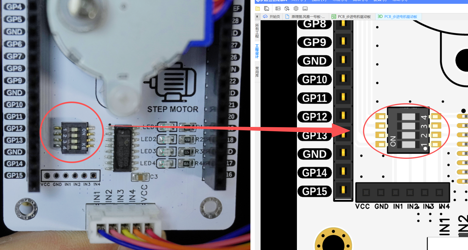
Meanwhile, turn on the DIP switches on the Fuya No. 1 Board - Stepper Motor Driver Board:
The overall connection is shown in the following figure:
The sample code is as follows, located in the folder of the supporting materials: elegance-devkit v1\Demo\04 GPIO_StepMotor: