It introduces MCU fundamentals, chip bus and registers, and explains the importance of registers, followed by Raspberry Pi Pico GPIO overview.
COMPONENTS
PROJECT DESCRIPTION
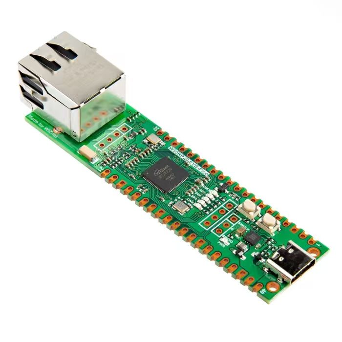
【Preliminary Note】The original hardware example in this article was written based on the RP2040. The actual hardware used in this hands-on demonstration features the W55RP20 as the main controller chip. The circuit logic and UF2 flashing operation principles are universally applicable, with only the main controller model differing. The original chip model mentioned in the circuit descriptions below is provided for reference purposes only.
Hardware Explanation
Basic Concepts and Architecture of MCU
Before we start learning about the GPIO of the Raspberry Pi Pico, let's first explain several core "hardware basic concepts" in simple terms. The Raspberry Pi Pico is an MCU development board, and you can understand an MCU (Microcontroller Unit) as an ultra-miniature dedicated computer — it cannot handle as many tasks as our desktop or laptop computers, but it is specifically responsible for controlling a certain electronic device (such as a smart light, a remote control, or a small toy you make with the Raspberry Pi Pico): for example, when you use the Pico to control an LED to turn on and off, the core that "issues commands and manages execution" is the MCU.
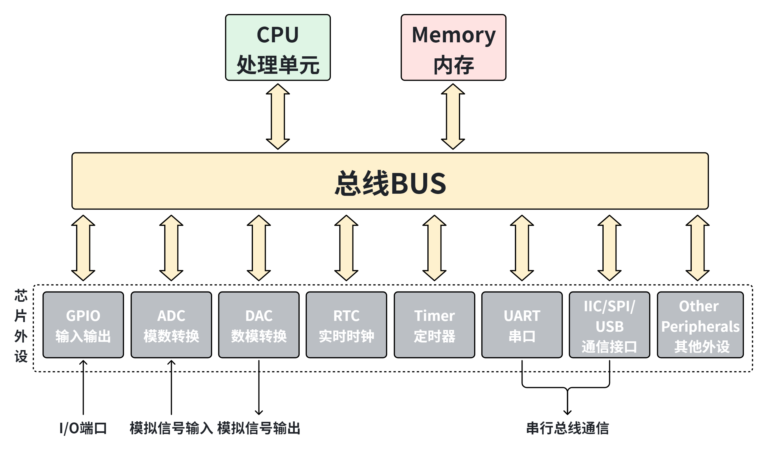
MCU (Microcontroller) is widely used to control all types of electronic devices, and an MCU consists of a CPU (Central Processing Unit), a memory unit, and additional circuits that implement various peripheral support functions:
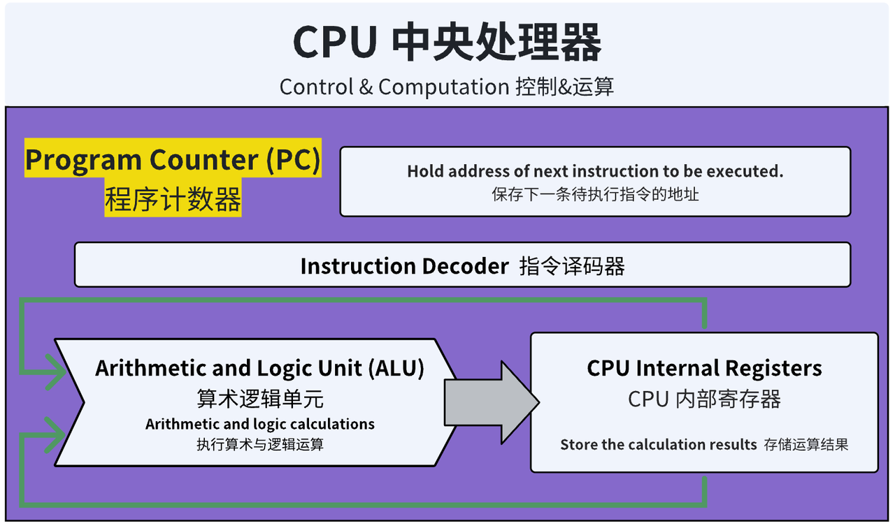
CPU (Processing Unit): The CPU operates by reading programs and executing instructions, which include reading data, performing calculations and comparisons, and generating other operations based on the comparison results; simply put, it is responsible for "thinking and issuing commands", such as judging "whether it is time to turn on the LED now" and "calculating what the sensor data is", and all the program code you write is executed by the CPU.
Memory (storage device): The functions of a storage device include storing data (such as the values collected by a temperature sensor) and storing the program itself;
Peripherals (the "limbs and senses" of an MCU): Peripherals can implement functions such as analog-to-digital conversion, signal input and output, time measurement, time monitoring, and host communication, and they are responsible for "handling the specific tasks": for example,
Want to light up an LED? Use the GPIO (General Purpose Input/Output peripheral) as the "hand" to control the circuit;
Want to read the temperature? Rely on the ADC (Analog-to-Digital Conversion peripheral) as the "sensory organ" to convert the analog signal from the sensor into a digital signal that the CPU can understand;
Want to transfer data with a computer? Use UART/USB (communication peripherals) as your "mouth and ears".
Peripherals, memory and the CPU are connected via a bus, which acts like a "highway" inside the MCU:
The Relationship Between Memory, CPU, Bus and Peripherals
All data and instructions must be transmitted via the bus: for example, if the CPU wants the GPIO to turn on the LED, it has to send the "LED-on command" to the GPIO peripheral through the bus; the sensor data read by the peripheral also has to be transmitted to the CPU via the bus.
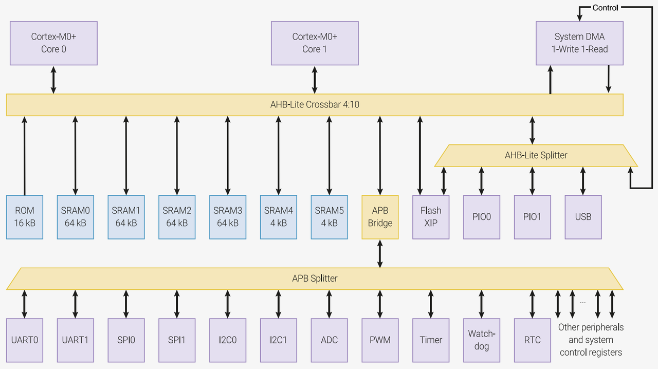
The bus structure of the Raspberry Pi Pico is as follows:
Dual-core microcontroller system architecture
It can be seen that Core 0 and Core 1 are connected to the DMA unit, SRAM memory unit, APB bus bridge and some high-speed peripherals (such as FLASH XIP, PIO, USB, etc.) through the AHB high-speed bus matrix structure. The APB bus bridge is connected to the APB bus, which is mounted with other low-speed peripherals, such as UART, SPI, IIC, ADC, PWM, timers, watchdog, RTC real-time clock, etc.
When we intend to use a certain peripheral to implement a specific function, such as controlling a GPIO to light up an LED, we are essentially operating "registers": they are "special dedicated storage circuits" inside the CPU or in peripheral circuits like GPIO and ADC, and are a type of ultra-high-speed temporary storage unit — far faster than conventional memory; yet due to the precious internal space of the chip, their quantity is very limited (unlike memory which can store a large volume of data).Each peripheral (such as GPIO or timer) corresponds to several "dedicated registers", and when the CPU wants to control a certain peripheral, it only needs to directly access the registers corresponding to that peripheral.
Registers can be divided into the following two types:
Special Registers: These serve dedicated fixed purposes and cannot be used arbitrarily — for instance, the register that controls GPIO pins acts as an "exclusive drawer" dedicated to the I/O port, which can only be used to configure the input/output state and high/low level of GPIO; the register that manages the timer is solely responsible for setting the timing duration.
General-purpose register: serves as the CPU's own "temporary workbench", which is used to store information such as calculation results and the CPU's current execution state, and programmers can flexibly use it to assist program operation.
CPU controls peripheral devices by reading from and writing to the special registers corresponding to the peripherals to issue commands or read data:
Want to set a certain GPIO pin to output a high level? Just locate the "GPIO Output Control" register and write a "1" to the corresponding bit position.
Want to read the sensor data from the ADC? Simply read the value stored in the "ADC Data" register directly.
Overview of GPIO on Raspberry Pi Pico
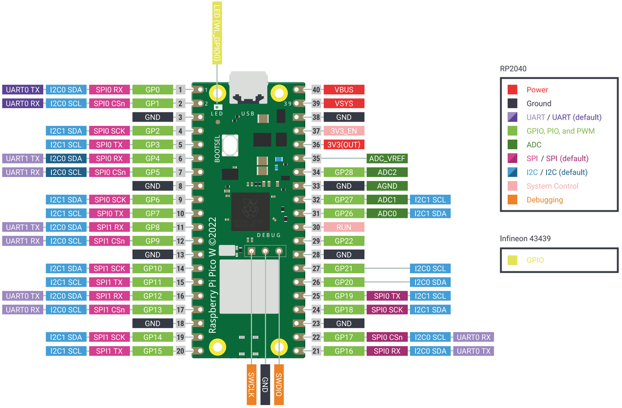
Introduction to the IO Port Functions of Raspberry Pi Pico
Simply put, the Raspberry Pi Pico has 26 available pins routed to the external header pins: GPIO 0 to GPIO 22 support digital signal input and output (following the TTL voltage level standard: high level is around 3.3V, low level is around 0V), while GPIO 26 to 28 are analog signal input pins.