It introduces MCU fundamentals, chip bus and registers, and explains the importance of registers, followed by Raspberry Pi Pico GPIO overview.
COMPONENTS
PROJECT DESCRIPTION
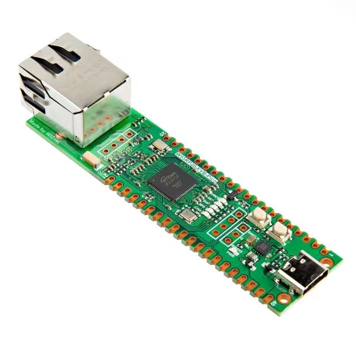
【Preliminary Note】The original hardware example in this article was written based on the RP2040. The actual hardware used in this hands-on demonstration features the W55RP20 as the main controller chip. The circuit logic and UF2 flashing operation principles are universally applicable, with only the main controller model differing. The original chip model mentioned in the circuit descriptions below is provided for reference purposes only.
General-purpose input/output (GPIO) is mainly initialized and controlled via the Pin class within the machine module; the Pin class is typically associated with physical GPIO pins capable of driving output voltages and reading input voltages, featuring methods to control pin modes (such as IN and OUT) as well as to acquire and set digital logic levels. For analog control of pins, please refer to the ADC class.
1. Constructor method of the machine. Pin class
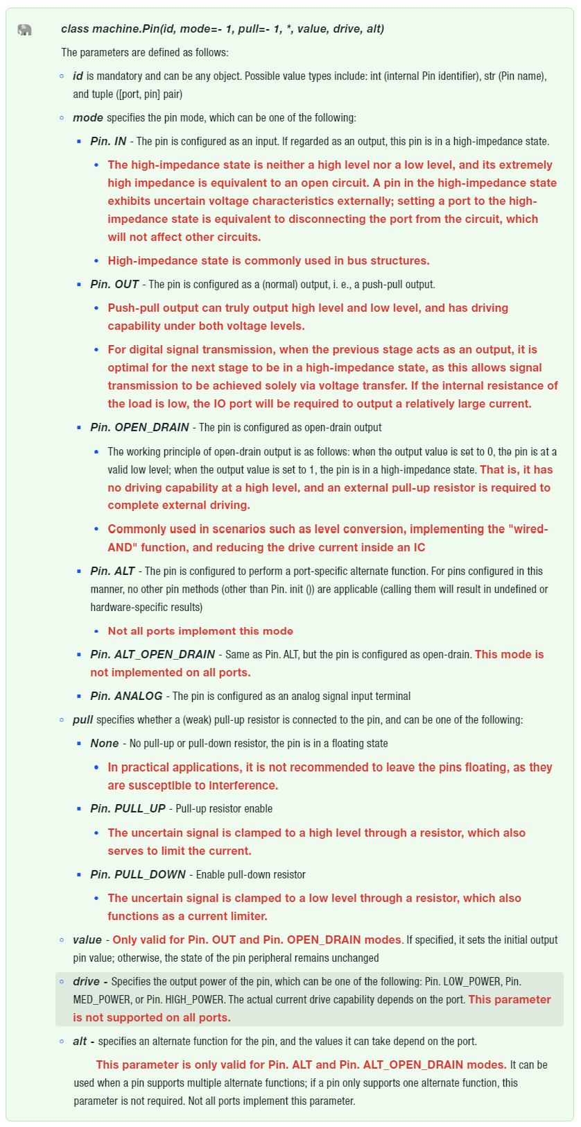
The constructor of the machine. Pin class is as follows:
As mentioned above, the Pin class allows setting alternate functions for a specific pin, but it does not specify any further operations on such pins. Typically when configuring peripherals that require GPIO, such as initializing a serial port, the constructor of the corresponding pin will be automatically invoked for initialization.
2. Other methods of the machine. Pin class
Method
Description
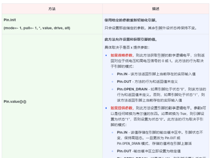
Pin.init
(mode=- 1, pull=- 1, *, value, drive, alt)
Reinitialize the pin with the given parameters.
Only the specified parameters will be configured, while the status of other pin peripherals will remain unchanged.
Pin.value([x])
This method allows setting and getting the value of the pin.
depending on whether x isprovided, the parameters are as follows:
If the parameter is omitted, this method will acquire the digital logic level of the pin, and return 0 or 1 corresponding to the low-voltage and high-voltage signals respectively. The behavior of this method depends on the mode of the pin:
Pin. IN - This method returns the actual input value currently present on the pin
Pin. OUT - The behavior and return value of this method are undefined
Pin. OPEN_DRAIN - If the pin is in state "0", the behavior and return value of this method are undefined; otherwise, if the pin is in state "1", this method returns the actual input value currently present on the pin
If a parameter is provided, this method sets the digital logic level of the pin. The parameter x can be anything that can be converted to a Boolean value. If the conversion results in True, the pin is set to the "1" state; otherwise, it is set to the "0" state. The behavior of this method depends on the pin's mode:
Pin. IN - This value is stored in the output buffer of the pin. The pin status remains unchanged and stays in a high-impedance state. Once the pin is switched to Pin. OUT or Pin. OPEN_DRAIN mode, the stored value will be activated on the pin.
Pin. OUT - The output buffer is immediately set to the specified value
Pin. OPEN_DRAIN - If the value is "0", the pin is set to a low-voltage state; otherwise, the pin is set to a high-impedance state
When setting a value, this method returns None.
Pin.__call__([x])
Pin objects are callable.
The call method provides a quick shortcut to set and get the value of a pin. It is equivalent to Pin. value ([x]).
A function for configuring external interrupts for GPIO pins.
When the pin modes are different, the trigger sources of external interrupts also vary:
Pin. IN - The trigger source is the external value on the pin
Pin. OUT - The trigger source is the output buffer of the pin
Pin. OPEN_DRAIN - The trigger source is the output buffer in state "0" and the external pin value in state "1"
The parameters of the Pin. irq method are defined as follows:
handler - Interrupt callback function, which is called when an interrupt is triggered. A Pin instance can be passed into this callback function
trigger configuration specifies the events that can generate interrupts. The possible values are as follows:
Pin. IRQ_FALLING - Falling edge interrupt
Pin. IRQ_RISING - Rising Edge Interrupt
Pin. IRQ_LOW_LEVEL - Low Level Interrupt
Pin. IRQ_HIGH_LEVEL - High Level Interrupt
priority sets the priority of the interrupt. The available priority levels vary depending on the specific chip (external interrupt priority setting is not supported on Raspberry Pi Pico). Meanwhile, the larger the value of priority, the higher the external interrupt priority of the corresponding IO pin
wake Select this interrupt to wake up the system from its power mode.
hard If true, hardware interrupts are used.
This method returns a callback object.
Pin.low()
Set the pin to low-level output.
Pin.high()
Set the pin to high-level output.
Pin.mode([mode])
Get or set the pin mode.
Pin.pull([pull])
Gets or sets the pull-up state of the pin.
Pin.drive([drive])
Gets or sets the pin drive strength.
The Raspberry Pi Pico does not support the setting of drive strength.