Embedded 101: MicroPython Signal Class – Portable GPIO Code Across Boards
It explains MicroPython machine.Signal class, its logic inversion feature, constructors and commonly used control methods.
COMPONENTS
PROJECT DESCRIPTION
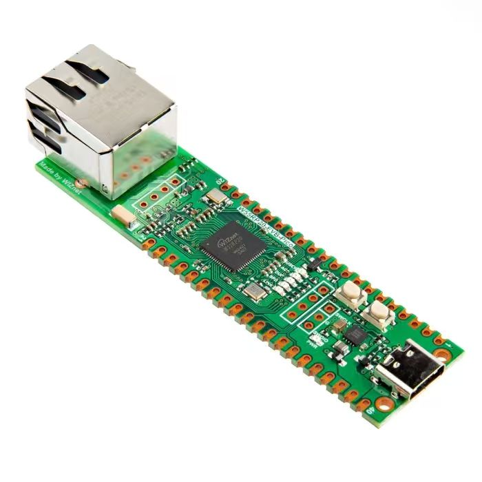
【Preliminary Note】The original hardware example in this article was written based on the RP2040. The actual hardware used in this hands-on demonstration features the W55RP20 as the main controller chip. The circuit logic and UF2 flashing operation principles are universally applicable, with only the main controller model differing. The original chip model mentioned in the circuit descriptions below is provided for reference purposes only.
1. Constructor method of the machine. Signal class
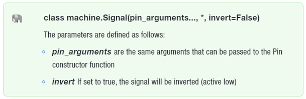
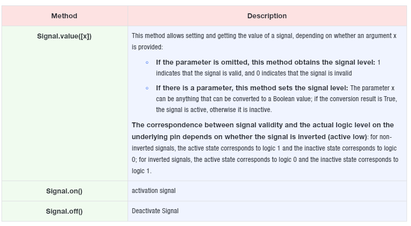
The Signal class is a further encapsulation of the Pin class. Through the Signal class, we can configure whether to invert the logic of a specific pin (simply put, originally we set high level as logic 1 and low level as logic 0; after inversion, we can set high level as logic 0 and low level as logic 1), thereby logically separating the control from the actual physical quantity.
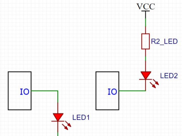
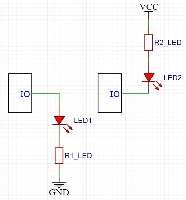
For example, in the following two schemes of controlling MCU and LED with different circuit connections, if you directly use Pin for control, you need to use the following respectively: led_pin (1), led_pin (0) to turn on the LED.
After using the Signal class, we can use the same method (e. g., led_pin (1)) to control the turning on of the LED without paying attention to the differences in the external connection circuits. By using the Signal class, we can ignore the specific physical distinction between high and low levels, so that our program only needs to modify some parameters in the Signal class to run without difference on most circuit boards with different connection modes of external device circuits without generating BUGs.
The Signal class is applicable to the following application scenarios:
Output high and low levels to control external sensors, for example: software-implemented PWM to drive motors, buzzers or LED lights, control the on/off of digital tubes, and control the opening and closing of relays
Read the high and low levels sent by external sensors, for example: detecting whether a key is pressed, and reading the digital outputs of reed switches, infrared sensors, humidity sensors and flame sensors
There are two constructors for Signal:
By directly passing the required Pin parameters to the Signal constructor, there is no need to create an intermediate Pin object. It should be noted that this method is not necessarily applicable to all development boards!
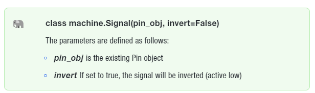
By wrapping the existing Pin object (this method is applicable to all development boards):