Wiznet makers

ruilixin6

Published August 01, 2026 ©

51 UCC

0 VAR

0 Contests

0 Followers

0 Following

Embedded 101: MicroPython Pitfalls – Signal Class for Circuit Level Compatibility

This experiment uses MicroPython Signal class on Fengya No.1 board to control two LEDs with different wiring by setting invert parameter uniformly.

COMPONENTS
PROJECT DESCRIPTION

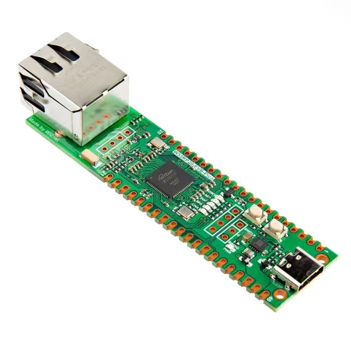
【Preliminary Note】The original hardware example in this article was written based on the RP2040. The actual hardware used in this hands-on demonstration features the W55RP20 as the main controller chip. The circuit logic and UF2 flashing operation principles are universally applicable, with only the main controller model differing. The original chip model mentioned in the circuit descriptions below is provided for reference purposes only.

Tweet

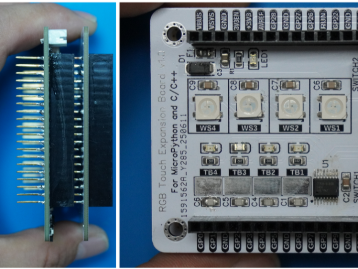
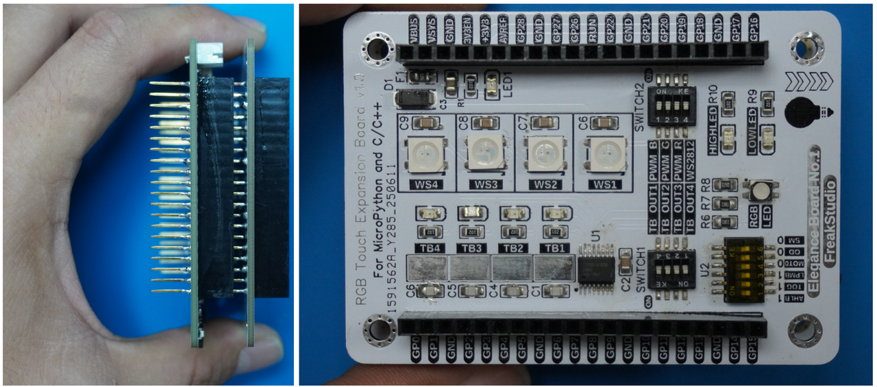
In the following experiment, we need to insert the Fengya No. 1 Board - Colorful Touch Expansion Board into the Fengya No. 1 Board - Universal Compatible Expansion Board:
In the following routine, we use the Signal class to control LEDs connected to two different circuits, where GP17 is connected to an LED whose cathode is tied to ground, so the corresponding GPIO lights it up by outputting a high level; while the LED connected to GP16 has its anode connected to + 3V3, so the corresponding GPIO lights it up by outputting a low level. We use the Signal class to wrap the existing Pin object, ultimately enabling control of the LED lighting with the same method.
The code is as follows:
# Python env   : MicroPython v1.23.0
# -*- coding: utf-8 -*-        
# @Time    : 2024/6/21 上午10:32   
# @Author  : 李清水            
# @File    : main.py       
# @Description : Signal类实验,完成对两个不同电路连接的LED进行控制

# ======================================== 导入相关模块 ========================================

# 硬件相关的模块
from machine import Pin, Signal
# 时间相关的模块
import time

# ======================================== 全局变量 ============================================

# ======================================== 功能函数 ============================================

# ======================================== 自定义类 ============================================

# ======================================== 初始化配置 ==========================================

# 上电延时
time.sleep(3)
# 打印调试信息
print("FreakStudio : Signal Class Test")

# 设置GPIO 17为LED1(共阳极)输出引脚,下拉电阻使能
LED1_Pin = Pin(17, Pin.OUT, Pin.PULL_DOWN)
# 设置GPIO 16为LED2(共阴级)输出引脚,下拉电阻使能
LED2_Pin = Pin(16, Pin.OUT, Pin.PULL_DOWN)

# ========================================  主程序  ============================================

# 不使用Signal类,直接使用Pin类时需要考虑外部电路的差异,输入不同电平来点亮LED灯
# LED1输入高电平点亮
LED1_Pin.value(1)
# LED2输入低电平点亮
LED2_Pin.value(0)

# 使用Signal类包装现有的Pin对象
# 对于LED1_Pin不使用反转,高电平-1、低电平-0
LED1 = Signal(LED1_Pin, invert=False)
# 对于LED2_Pin使用反转,高电平-0、低电平-1
LED2 = Signal(LED2_Pin, invert=True)

# 现在可以使用一个方法进行两个LED灯的点亮
LED1.on()
LED2.on()

# 等待5秒
time.sleep(5)

# 获取信号状态
print("LED 1 value :", LED1.value())
print("LED 2 value :", LED2.value())

# 获取引脚状态
print("LED1_Pin value :", LED1_Pin.value())
print("LED2_Pin value :", LED2_Pin.value())

# 关闭两个LED灯
LED1.off()
LED2.off()

# 等待1秒
time.sleep(1)

# 获取信号状态
print("LED 1 value :", LED1.value())
print("LED 2 value :", LED2.value())

# 获取引脚状态
print("LED1_Pin value :", LED1_Pin.value())
print("LED2_Pin value :", LED2_Pin.value())
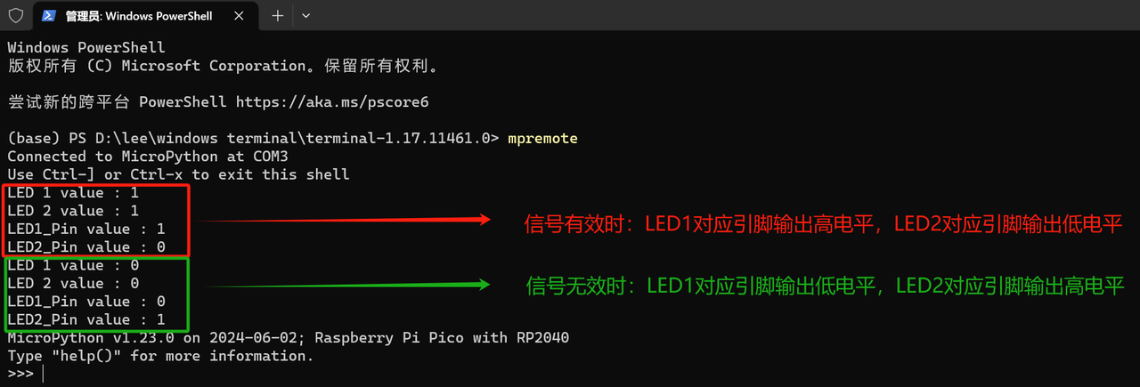
Burn the code, open the terminal, use mpremote to connect to the Raspberry Pi Pico, and you will see the following output:
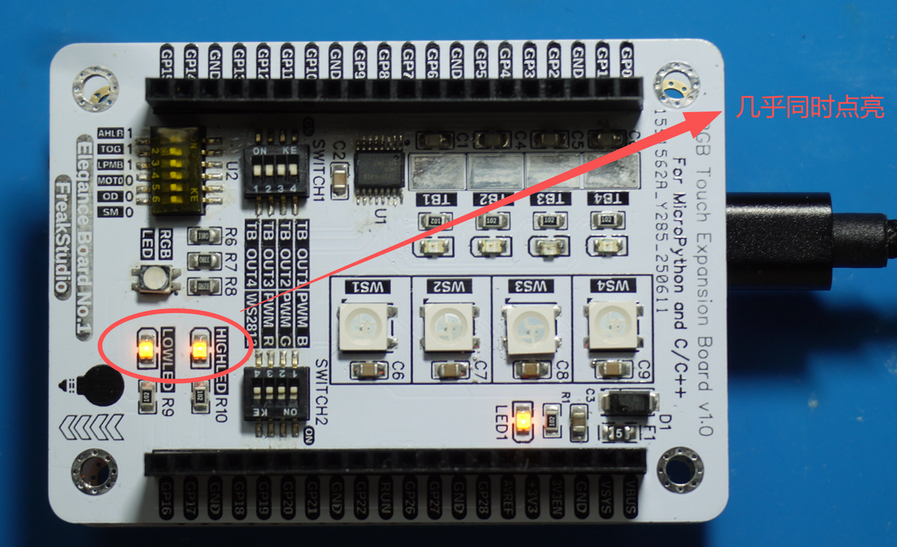
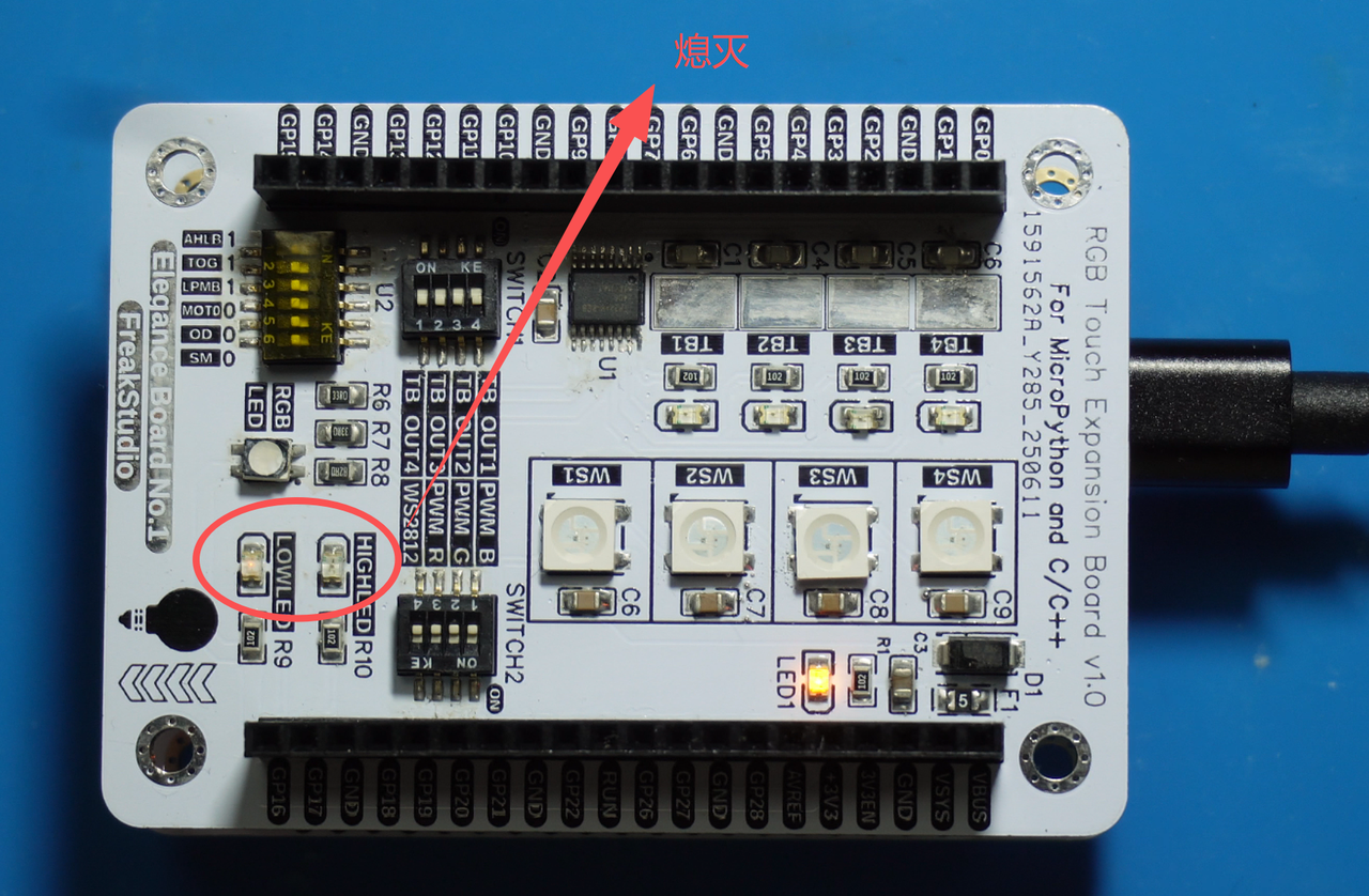
We can see that on the Fuya No. 1 Board - Colorful Touch Expansion Board, the HIGHLED and LOWLED are lit up simultaneously first, and then turned off at the same time:
Documents
Comments Write