



DS3502 with MicroPython: Fast‑Write Mode & Waveform‑Generation Tips
Advanced usage of DS3502 fast‑write mode and waveform generation techniques in MicroPython embedded projects
- Custom DS3502 Class
In the code below, a driver for the DS3502 digital potentiometer is implemented. The I2C interface is used to control the position of the wiper register (WR), which changes the resistance value of the potentiometer.
Sample code:
# Python env   : MicroPython v1.23.0
# -*- coding: UTF-8 -*-
# @Time    : 2024/11/4 3:20 PM
# @Author  : Li Qingshui
# @File    : ds3502.py
# @Description : Driver module for digital potentiometer chip DS3502
# ======================================== Import related modules =========================================
# Import time‑related modules
import time
# Import MicroPython related modules
from micropython import const
# Import hardware‑related modules
from machine import I2C
# ======================================== Global variables ============================================
# ======================================== Function definitions ============================================
# ======================================== Custom classes ============================================
# Custom DS3502 digital potentiometer class
class DS3502:
    """
    DS3502 class for operating the DS3502 digital potentiometer chip over I2C bus to adjust resistance values.
    This class encapsulates I2C communication with DS3502. It provides functions to set the wiper register (WR) value, read current wiper position, and configure control register (CR) modes.
    Attributes:
        i2c (I2C): I2C instance used for communication with DS3502.
        addr (int): I2C address of DS3502 (range 0x28 to 0x2B).
        mode (int): Current operating mode (0 or 1), controls write speed and non‑volatile storage behaviour.
    Methods:
        __init__(self, i2c: I2C, addr: int):
            Initialize DS3502 class instance.
        write_wiper(self, value: int) -> None:
            Write to wiper register (WR) to set wiper position.
        read_control_register(self) -> int:
            Read value from control register (CR) to get current write‑mode setting.
        set_mode(self, mode: int) -> None:
            Set write mode of control register.
        read_wiper(self) -> int:
            Read value from wiper register (WR).
    """
    # Class variables: register addresses
    # Wiper register address
    REG_WIPER = const(0x00)
    # Control register address
    REG_CONTROL = const(0x02)

    def __init__(self, i2c: I2C, addr: int):
        """
        Initialize DS3502 class.
        Args:
            i2c (machine.I2C): I2C object for DS3502 communication.
            addr (int): DS3502 I2C address, between 0x28 and 0x2B.
        Raises:
            ValueError: Raised if address is outside 0x28‑0x2B range.
        """
        # Validate I2C address range
        if addr < 0x28 or addr > 0x2B:
            raise ValueError("Address must be between 0x28 and 0x2B")
        # Store I2C object
        self.i2c = i2c
        # Store I2C address
        self.addr = addr
        # Operating mode:
        #   0‑ write to WR and IVR, slow speed, CR = 00h
        #   1‑ write only to WR, fast speed, CR = 80h
        self.mode = 0

    def write_wiper(self, value: int) -> None:
        """
        Write wiper register (WR) to set wiper position.
        Args:
            value (int): Value to write into wiper register (0 to 127).
        Raises:
            ValueError: Raised if value is outside 0‑127 range.
        """
        # Validate input value range
        if value < 0 or value > 127:
            raise ValueError("Value must be between 0 and 127")
        # Write value to address 0x00 of DS3502 to update WR register
        self.i2c.writeto_mem(self.addr, DS3502.REG_WIPER, bytes([value]))
        # Apply delay depending on operating mode
        if self.mode == 0:
            # 100 ms delay for mode 0
            time.sleep_ms(100)

    def read_control_register(self) -> int:
        """
        Read control register (CR) value to determine current write mode.
        Args:
            None.
        Returns:
            int: Control‑register value (0 or 1 representing current mode).
        """
        # Dummy‑write to set target register address
        self.i2c.writeto_mem(self.addr, DS3502.REG_CONTROL, b'')
        # Generate repeated‑start condition and read control register
        data = self.i2c.readfrom_mem(self.addr, DS3502.REG_CONTROL, 1)
        # Update local mode attribute
        if data[0] == 0x80:
            self.mode = 1
        # Return current mode value
        return self.mode

    def set_mode(self, mode: int) -> None:
        """
        Set write mode for control register.
        Args:
            mode (int): Mode selection, either 0 or 1.
        Raises:
            ValueError: Raised if mode is not 0 or 1.
        """
        if mode not in (0, 1):
            raise ValueError("Mode must be 0 or 1")
        # Write corresponding value to control register according to selected mode
        if mode == 0:
            # Set MODE bit to 0: write to WR and IVR
            self.i2c.writeto_mem(self.addr, DS3502.REG_CONTROL, bytes([0x00]))
            self.mode = 0
        else:
            # Set MODE bit to 1: write only to WR
            self.i2c.writeto_mem(self.addr, DS3502.REG_CONTROL, bytes([0x80]))
            self.mode = 1

    def read_wiper(self) -> int:
        """
        Read wiper register (WR) value.
        Args:
            None.
        Returns:
            int: Current wiper‑position value (0 to 127).
        """
        # Dummy‑write to set target wiper‑register address
        self.i2c.writeto_mem(self.addr, DS3502.REG_WIPER, b'')
        # Generate repeated‑start condition and read wiper register
        data = self.i2c.readfrom_mem(self.addr, DS3502.REG_WIPER, 1)
        # Return read wiper‑position value
        return data[0]
# ======================================== Initialization ==========================================
# ======================================== Main program ===========================================
Methods provided by this custom class:
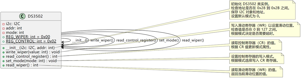
__init__ initialization method Pass in only the I2C interface object and DS3502 I2C address. Perform address‑range check ensuring address lies between 0x28 and 0x2B. Raise ValueError upon invalid address. Store I2C object and address, initialize mode to 0. Mode 0 means slow‑write mode, mode 1 means fast‑write mode.
write_wiper method for setting wiper‑register value Changes potentiometer resistance by writing to wiper register. Validate input value is within 0‑127. Use writeto_mem to write value into REG_WIPER register to update wiper position. When mode equals 0 (slow‑write mode), execute a 100 ms delay.
read_control_register method for reading control‑register value Reads CR register value to inspect mode status. Uses readfrom_mem to fetch REG_CONTROL content. If received byte equals 0x80, set self.mode to 1 and return current mode.
set_mode method for setting control‑register mode Sets control‑register value based on mode argument. Check input is either 0 or 1, otherwise raise ValueError. Write corresponding register value to REG_CONTROL and assign self.mode.
read_wiper method for reading wiper‑register value Reads current wiper‑register value using readfrom_mem against REG_WIPER.
- Waveform Generator Implemented with DS3502
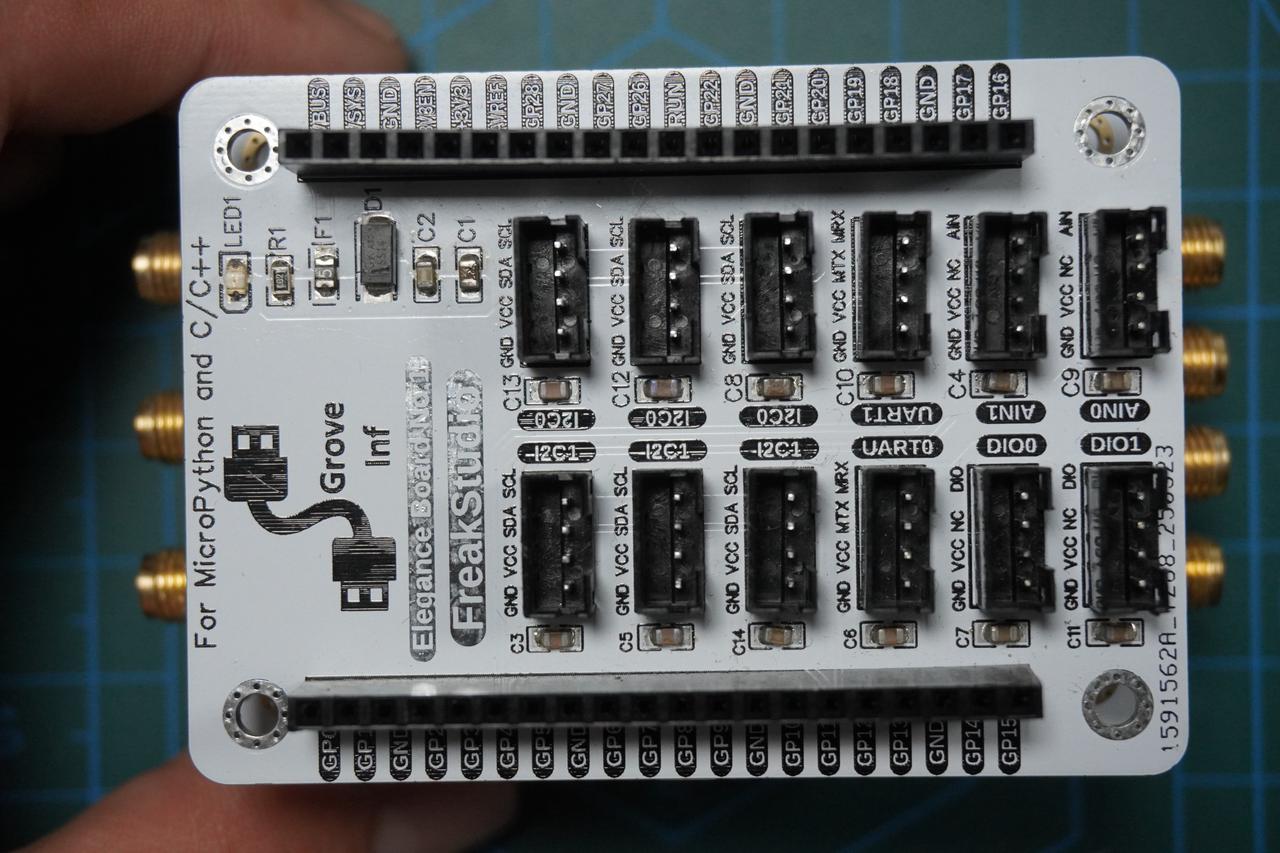
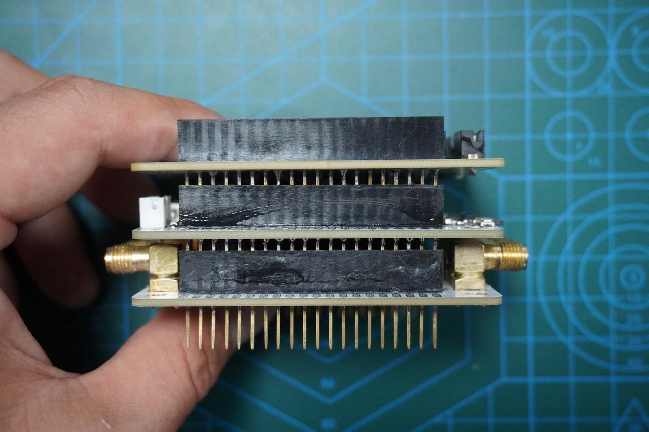
Insert Elegance‑One Grove‑Interface Expansion Board onto Elegance‑One Universal Compatible Expansion Board. Use HY2.0‑4P flat cable to connect the I2C1 port on the Elegance‑One Grove‑Interface Expansion Board to the I2C port on the GraftSense‑DS3502‑based Digital Potentiometer Module.
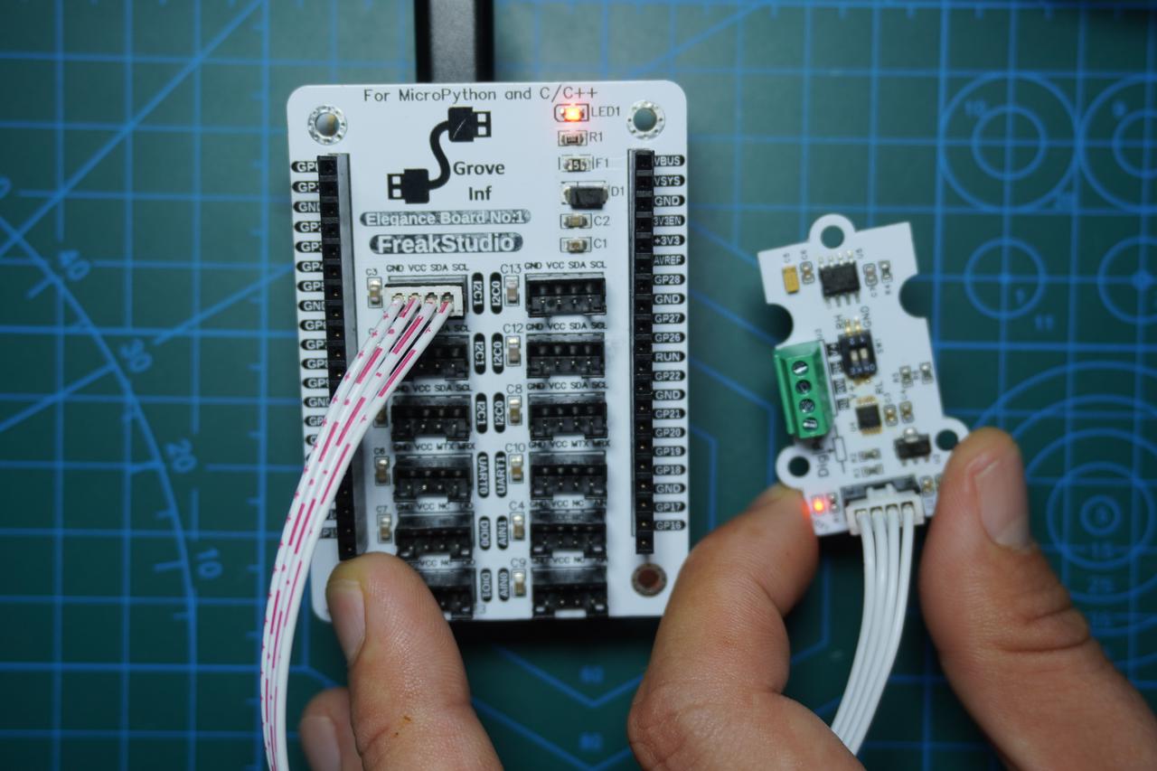
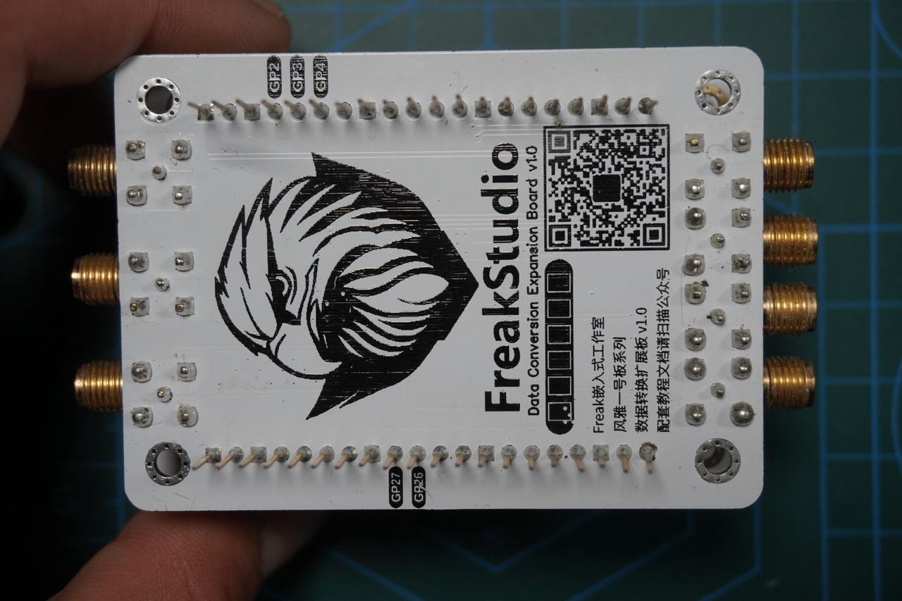
Then plug the Elegance‑One Universal Compatible Expansion Board onto the Elegance‑One Data‑Conversion Board. Turn on the SCL, SDA and RDY switches of the SWITCH1 DIP switch on the Data‑Conversion Board. Also enable the ADC1 switch option of SWITCH2.
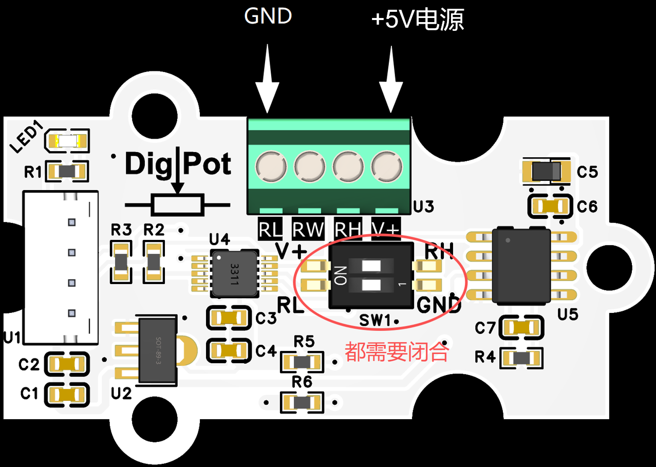
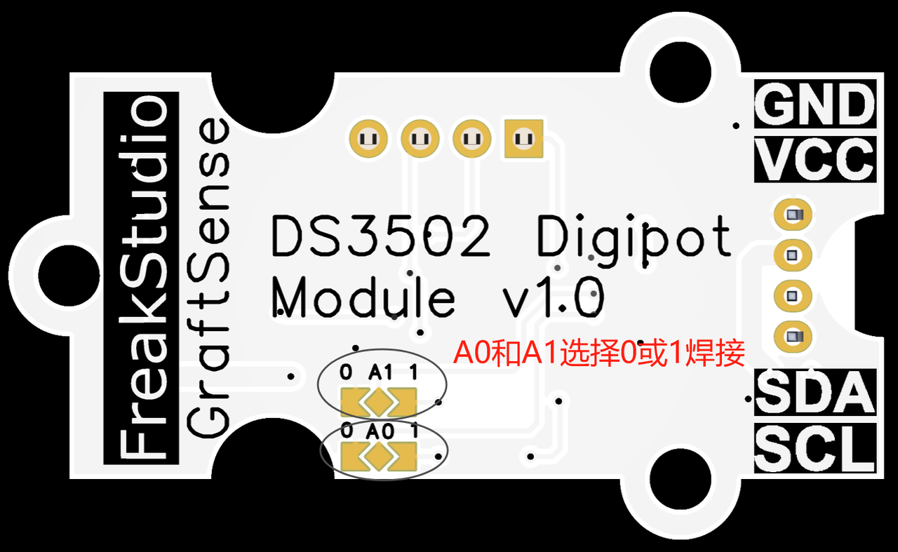
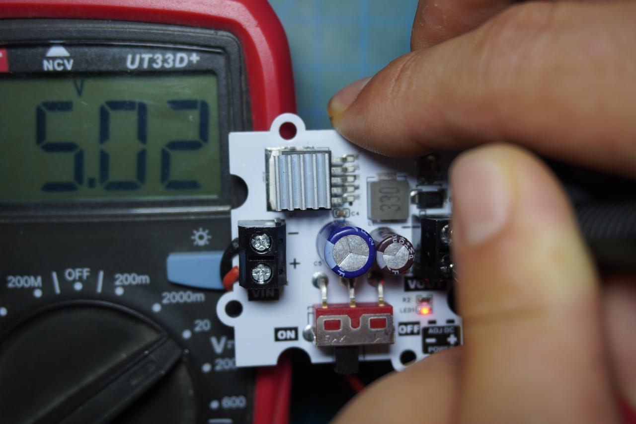
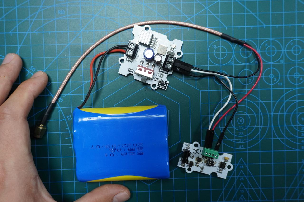
On the reverse side of the GraftSense‑DS3502‑based Digital Potentiometer Module, configure device address by short‑circuiting solder pads of address pins A0 and A1 to GND or VCC. Toggle the RL switch of SW1 to short to GND and toggle V+ switch to short to RH. Supply +5 V power to RL and V+ terminals on U3 (recommended: GraftSense‑LM2596S‑based adjustable power‑supply module).
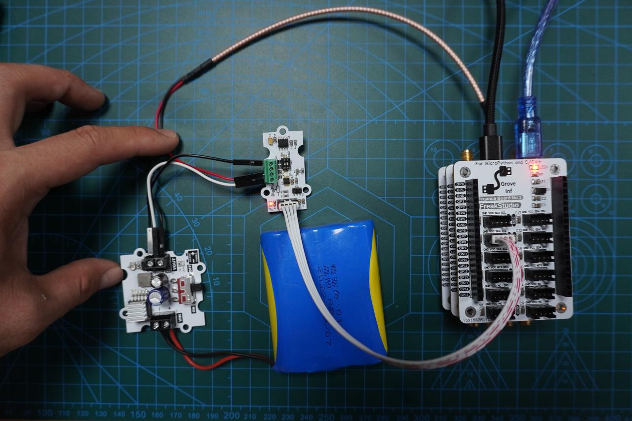
Physical photos after assembly:
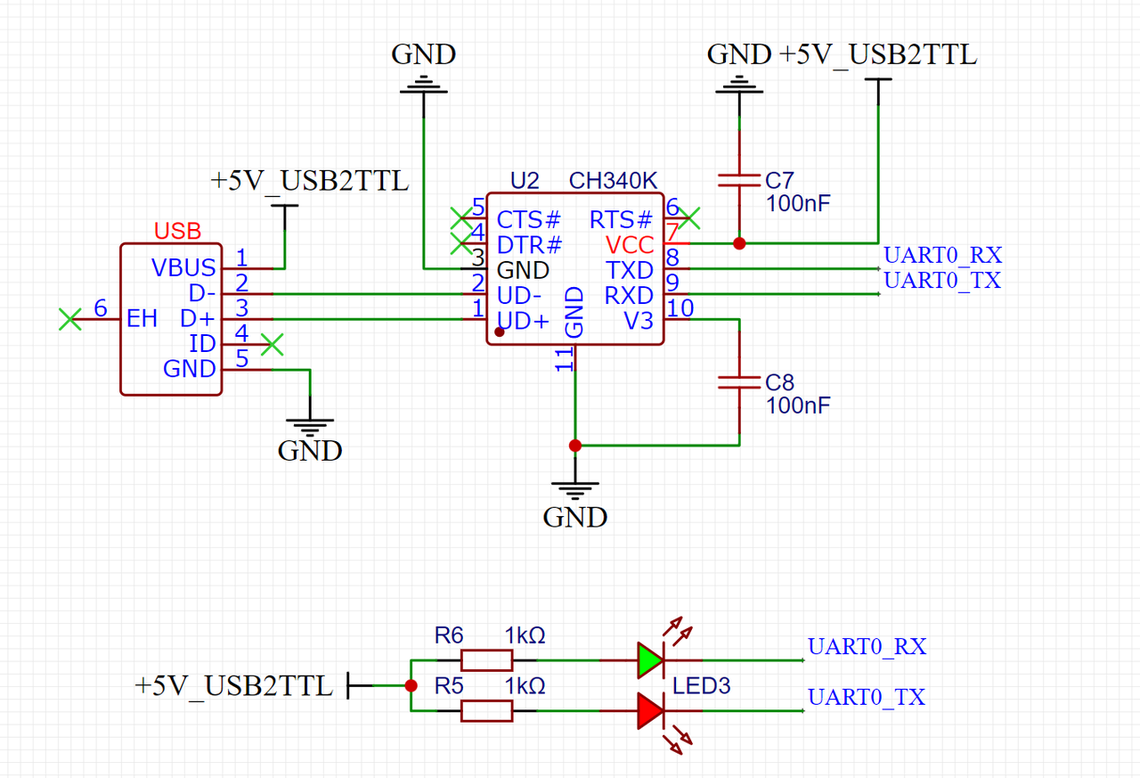
Connect Mini‑USB cable to serial port on Elegance‑One Universal Compatible Expansion Board. GP0 and GP1 are default hardware UART0 pins for Raspberry Pi Pico.
Signal output on GraftSense‑DS3502‑based Digital Potentiometer Module is the RW pin of terminal block U3. Use SMA‑to‑DuPont‑wire adapter cable to connect RW output of U3 to the ADC0 SMA input port on Elegance‑One Data‑Conversion Board.
Full connection diagram:
Component wiring table:
Source code is located in resource package under elegance‑devkit v1\Demo\64 DAC_Digipot.
The example below runs on Raspberry Pi Pico, uses DS3502 digital potentiometer to generate different waveforms and outputs ADC0‑sampled voltage values over serial port.
The WaveformGenerator class from previous section is saved into separate file dac_waveformgenerator.py with several modifications.
# Python env   : MicroPython v1.23.0
# -*- coding: utf-8 -*-
# @Time    : 2025/3/21 7:13 PM
# @Author  : Li Qingshui
# @File    : dac_waveformgenerator.py
# @Description : Class for generating sine, triangle and sawtooth waveforms with DS3502 chip
# This code is developed by leeqingshui, released under CC BY‑NC 4.0 license
# ======================================== Import related modules =========================================
# Import math library for sine‑wave calculation
import math
# Import hardware‑related modules
from machine import Timer
# Import ds3502 module for digital‑potentiometer control
from ds3502 import DS3502
# ======================================== Global variables ============================================
# ======================================== Function definitions ============================================
# ======================================== Custom classes ============================================
class WaveformGenerator:
    def __init__(self, dac: 'DS3502', frequency: float = 1, amplitude: float = 1.65, offset: float = 1.65,
                 waveform: str = 'sine', rise_ratio: float = 0.5, vref: float = 3.3) -> None:
        """
        Initialize waveform‑generator instance.
        Sets basic parameters including DS3502 object, signal frequency, amplitude, DC offset, waveform type, triangle‑wave rise ratio and reference voltage.
        Args:
            dac (DS3502): DS3502 digital potentiometer instance for waveform generation.
            frequency (float, optional): Signal frequency, default 1 Hz. Must be greater than 0 and ≤10 Hz.
            amplitude (float, optional): Signal amplitude, default 1.65V. Must be between 0 and vref.
            offset (float, optional): DC offset voltage, default 1.65V. Must be between 0 and vref.
            waveform (str, optional): Waveform type: 'sine', 'square', 'triangle'. Default 'sine'.
            rise_ratio (float, optional): Triangle‑wave rise‑edge ratio, default 0.5, valid range 0‑1.
            vref (float, optional): Reference voltage, default 3.3V. Must be greater than 0.
        Returns:
            None: This method returns nothing.
        Raises:
            ValueError: Raised when input parameters are outside valid ranges.
        """
        # Parameter validation
        if not (0 < frequency <= 10):
            raise ValueError("Frequency must be between 0 and 10 Hz.")
        if not (0 <= amplitude <= vref):
            raise ValueError(f"Amplitude must be between 0 and {vref}V.")
        if not (0 <= offset <= vref):
            raise ValueError(f"Offset must be between 0 and {vref}V.")
        if not (0 <= amplitude + offset <= vref):
            raise ValueError(f"Amplitude + offset must be between 0 and {vref}V.")
        if waveform not in ['sine', 'square', 'triangle']:
            raise ValueError("Waveform must be 'sine', 'square', or 'triangle'.")
        if not (0 <= rise_ratio <= 1):
            raise ValueError("Rise ratio must be between 0 and 1.")
        if vref <= 0:
            raise ValueError("Vref must be greater than 0.")
        # Store DS3502 object
        self.dac = dac
        # Initialize timer object
        self.timer = Timer(-1)
        # Save waveform‑generator parameters
        self.frequency = frequency
        self.amplitude = amplitude
        self.offset = offset
        self.waveform = waveform
        self.rise_ratio = rise_ratio
        self.vref = vref
        # Fixed sample‑point count: 50 samples
        self.sample_rate = 50
        # DS3502 resolution: 7‑bit (128 levels)
        self.dac_resolution = 127
        # Generate sample‑point array based on waveform setting
        self.samples = self.generate_samples()
        # Initialize current sample index
        self.index = 0

    def generate_samples(self) -> list[int]:
        """
        Generate sample‑point array for selected waveform.
        Returns:
            list[int]: List of sample values converted to DS3502 integer codes.
        """
        # Helper function to convert voltage to DS3502 code
        def to_dac_value(voltage):
            # DS3502 7‑bit resolution, voltage range 0 to vref
            return int(voltage / self.vref * self.dac_resolution)
        samples = []
        if self.waveform == 'sine':
            for i in range(self.sample_rate):
                angle = 2 * math.pi * i / self.sample_rate
                voltage = self.offset + self.amplitude * math.sin(angle)
                samples.append(to_dac_value(voltage))
        elif self.waveform == 'square':
            for i in range(self.sample_rate):
                if i < self.sample_rate // 2:
                    voltage = self.offset + self.amplitude
                else:
                    voltage = self.offset - self.amplitude
                samples.append(to_dac_value(voltage))
        elif self.waveform == 'triangle':
            for i in range(self.sample_rate):
                if i < self.sample_rate * self.rise_ratio:
                    voltage = self.offset + 2 * self.amplitude * (
                            i / (self.sample_rate * self.rise_ratio)) - self.amplitude
                else:
                    voltage = self.offset + 2 * self.amplitude * (
                            (self.sample_rate - i) / (self.sample_rate * (1 - self.rise_ratio))) - self.amplitude
                samples.append(to_dac_value(voltage))
        return samples

    def update(self, t: Timer) -> None:
        """
        Timer callback function to output next sample point.
        Args:
            t (Timer): Timer object.
        """
        # Write current sample value into DS3502
        self.dac.write_wiper(self.samples[self.index])
        # Advance sample index
        self.index = (self.index + 1) % self.sample_rate

    def start(self) -> None:
        """
        Start waveform generator and enable timer.
        """
        self.timer.init(freq=self.frequency * self.sample_rate, mode=Timer.PERIODIC, callback=self.update)

    def stop(self) -> None:
        """
        Stop waveform generator and disable timer.
        """
        self.timer.deinit()
        self.index = 0
# ======================================== Initialization ==========================================
# ======================================== Main program ===========================================
Modifications made:
In __init__() initialization method Add reference voltage as an initialization parameter, allowing users to dynamically set reference voltage according to real‑world hardware instead of hard‑coding to 3.3 V. Change type annotation of argument dac to DS3502. Add parameter checks ensuring amplitude and offset do not exceed vref and validate vref > 0.
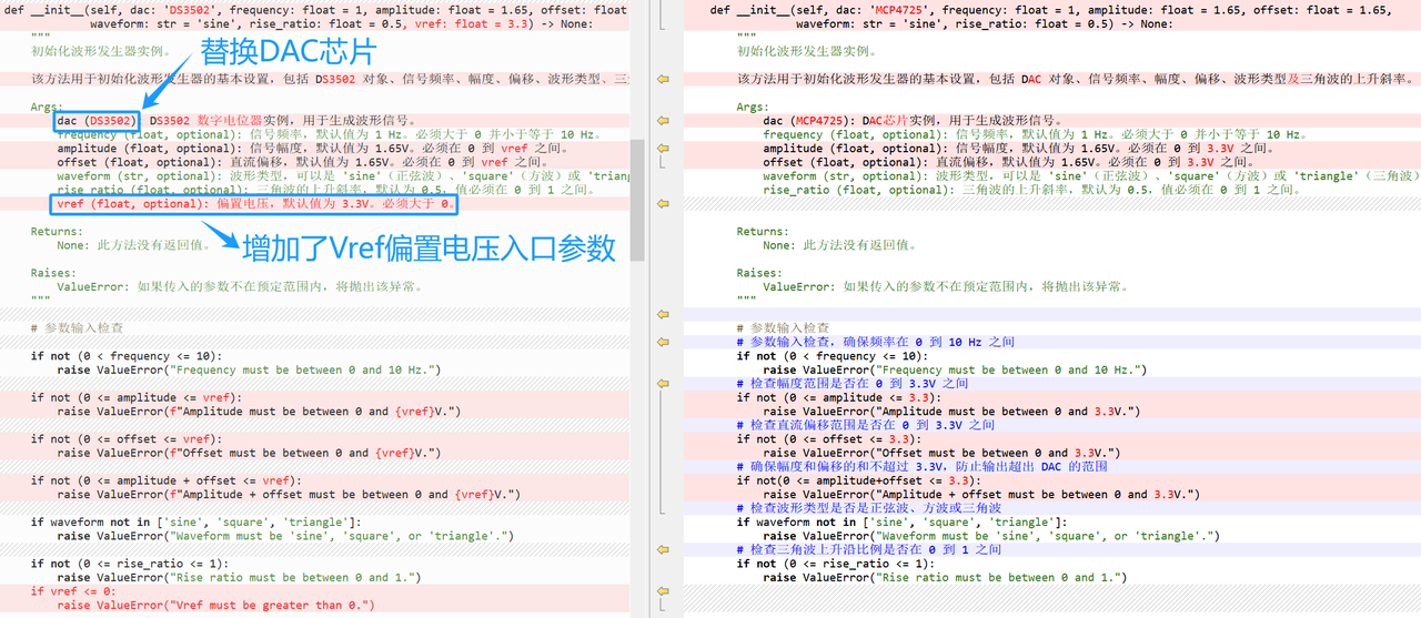
Change attribute dac_resolution from 12 to 7.
In generate_samples() method Adjust sample‑generation logic for DS3502 7‑bit resolution (128 levels), different from MCP4725 12‑bit (4096 levels).

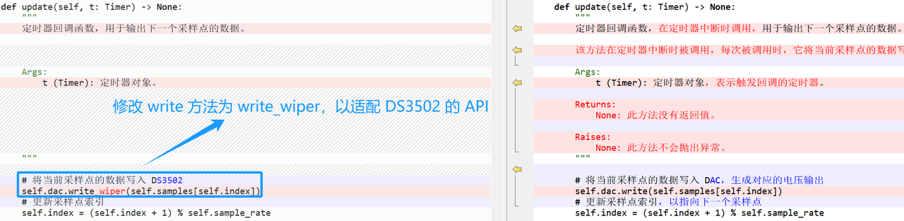
In timer‑callback update() function Replace write call with write_wiper to match DS3502 API.
Main‑program sample code:
# Python env   : MicroPython v1.23.0
# -*- coding: utf-8 -*-
# @Time    : 2025/3/21 3:04 PM
# @Author  : Li Qingshui
# @File    : main.py
# @Description : Output arbitrary waveforms using DS3502 digital potentiometer
# ======================================== Import related modules ========================================
# Import hardware‑related modules
from machine import ADC, Timer, Pin, I2C, UART
# Import time‑related modules
import time
# Import MicroPython internal‑structure access module
import micropython
# Import math library for sine‑wave calculation
import math
# Import ds3502 module for digital‑potentiometer control
from ds3502 import DS3502
# Import waveform‑generator module
from dac_waveformgenerator import WaveformGenerator
# ======================================== Global variables ============================================
# DS3502 chip address
DAC_ADDRESS = 0x00
# Voltage conversion factor
adc_conversion_factor = 3.3 / (65535)
# ======================================== Function definitions ============================================
def timer_callback(timer: Timer) -> None:
    """
    Timer callback for periodic ADC reading and invoking user‑defined callback.
    Args:
        timer (machine.Timer): Timer instance.
    Returns:
        None: This method returns nothing.
    Raises:
        None: This method raises no exceptions.
    """
    global adc, adc_conversion_factor
    value = adc.read_u16() * adc_conversion_factor
    micropython.schedule(user_callback, (value))

def user_callback(value: float) -> None:
    """
    User‑defined callback function to process ADC‑sampled voltage and send data over serial port.
    Args:
        value (float): Voltage value sampled by ADC.
    Returns:
        None: This method returns nothing.
    Raises:
        None: This method raises no exceptions.
    """
    global uart
    formatted_value = "{:.2f}".format(value)
    uart.write(str(formatted_value) + '\r\n')
# ======================================== Custom classes ============================================
# ======================================== Initialization ==========================================
# 3‑second delay for power‑on stabilization
time.sleep(3)
print("FreakStudio : Using Digital Potentiometer chip DS3502 to generate differential waveform")
# Create hardware I2C instance: I2C1, 400 kHz, SDA=Pin10, SCL=Pin11
i2c = I2C(id=1, sda=Pin(10), scl=Pin(11), freq=400000)
# Scan I2C‑bus slave devices
devices_list = i2c.scan()
print('START I2C SCANNER')
if len(devices_list) == 0:
    print("No i2c device !")
else:
    print('i2c devices found:', len(devices_list))
    for device in devices_list:
        if 0x28 <= device <= 0x2B:
            print("I2C hexadecimal address: ", hex(device))
            DAC_ADDRESS = device
# Create DS3502 object
dac = DS3502(i2c, DAC_ADDRESS)
# Set DS3502 to fast mode (write only to WR register)
dac.set_mode(1)
# Create UART instance with baudrate 115200
uart = UART(0, 115200)
uart.init(baudrate=115200,
          bits=8,
          parity=None,
          stop=1,
          tx=0,
          rx=1,
          timeout=100)
# Create ADC instance: ADC0‑GP26
adc = ADC(0)
# Create software‑timer object
timer = Timer(-1)
# Trigger timer_callback every 1 ms for ADC voltage sampling
timer.init(period=1, mode=Timer.PERIODIC, callback=timer_callback)
# ======================================== Main program ===========================================
# Generate sine wave
print("FreakStudio : Generate Sine Waveform : 10Hz, 1.5V, 1.5V")
wave = WaveformGenerator(dac, frequency=5, amplitude=1.5, offset=1.5, waveform='sine', vref = 5)
wave.start()
time.sleep(6)
wave.stop()
# Generate square wave
print("FreakStudio : Generate Square Waveform : 10Hz, 1.5V, 1.5V")
wave = WaveformGenerator(dac, frequency=5, amplitude=1.5, offset=1.5, waveform='square', vref = 5)
wave.start()
time.sleep(6)
wave.stop()
# Generate triangle wave
print("FreakStudio : Generate Triangle Waveform : 10Hz, 1.5V, 1.5V, 0.8")
wave = WaveformGenerator(dac, frequency=5, amplitude=1.5, offset=1.5, waveform='triangle', rise_ratio=0.8, vref = 5)
wave.start()
time.sleep(6)
wave.stop()
# Stop ADC sampling timer
timer.deinit()
Overall workflow is similar to the MCP4725 waveform‑generator example in previous section.
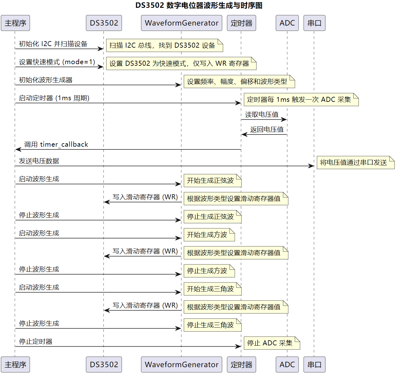
- Initialization: Initialize I2C bus, scan and connect DS3502 digital potentiometer. Initialize UART for data output, initialize ADC for output‑voltage acquisition, set‑up timer for periodic ADC sampling.
- Waveform generation: Use
WaveformGeneratorclass to produce sine, square and triangle waveforms. Control output voltage by setting wiper register (WR) values on DS3502. - Data acquisition and transmission: Every 1 ms the timer triggers
timer_callbackto read ADC samples, and sampled voltage values are sent out over serial port. - Waveform switching and termination: Each waveform runs for 5 seconds then stops before switching to next waveform. Finally de‑initialize timer and halt ADC sampling.
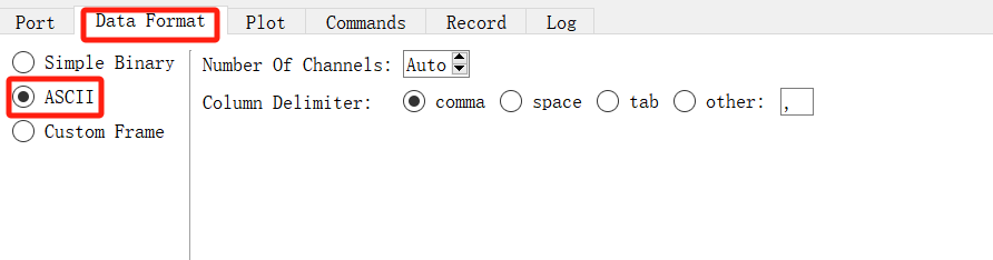
Launch SerialPlot software, select correct COM port for USB‑to‑TTL adapter and click Open.

Select ASCII for data format, keep remaining settings as default.

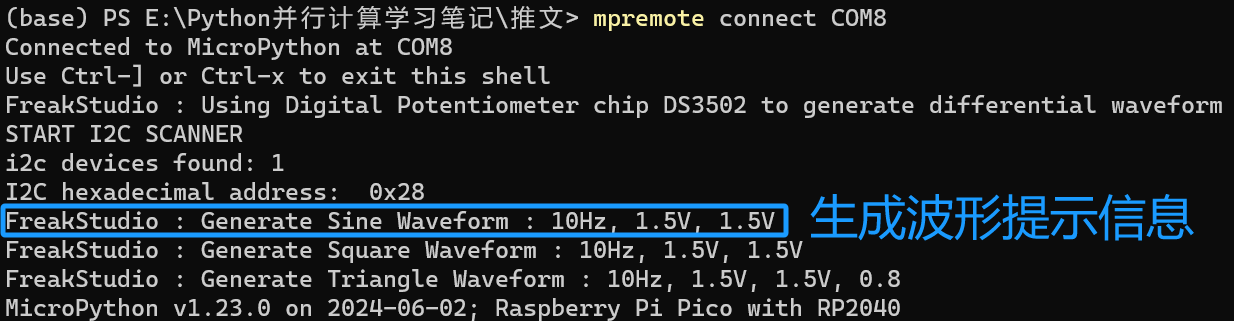
Flash firmware and open serial terminal, example output:
Inside SerialPlot you can observe output waveforms with correct frequency and amplitude.
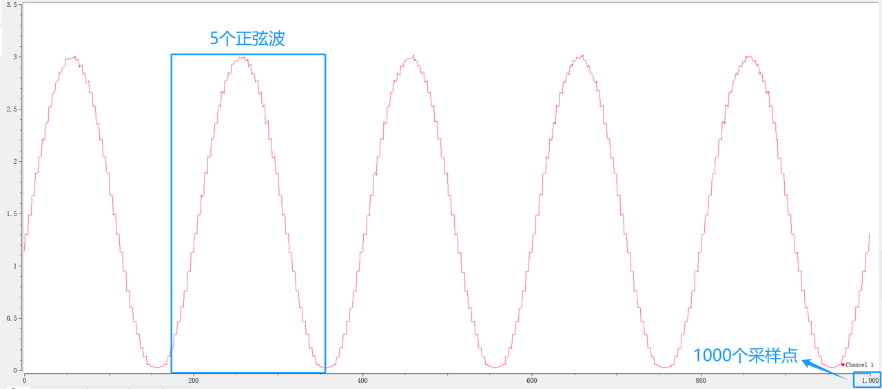
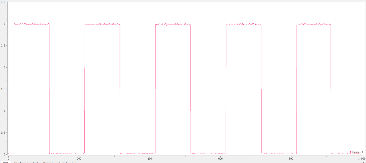
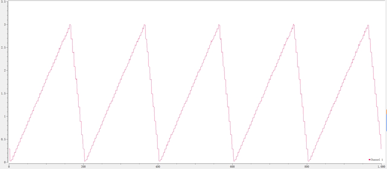
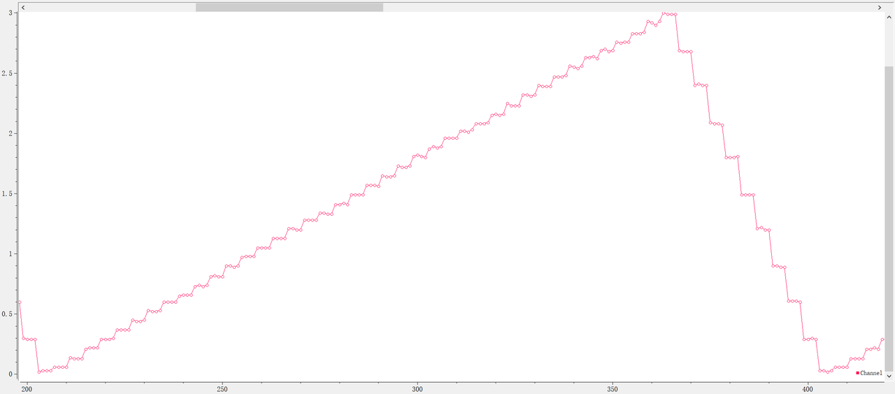
Noticeable stair‑step artefacts appear on generated waveforms because DS3502 only provides 7‑bit resolution. It is not suitable for high‑frequency or high‑precision use‑cases.