



DMA Deep‑Dive: Workflow, Transfer Modes & Real‑World Use‑Cases
DMA core knowledge covering operating workflow, transfer modes and typical embedded application scenarios
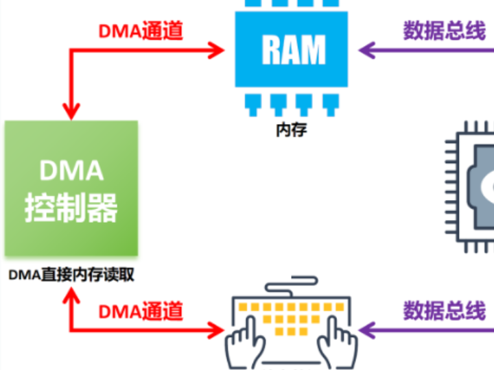
- DMA Direct Memory Access Introduction
In traditional data‑transfer approaches, the MCU CPU reads data from peripherals such as I2C, UART, ADC and stores it into memory, or reads data from memory and writes it to peripherals. This approach forces the CPU to continuously handle read‑write operations, which raises CPU load and degrades overall system performance.
DMA (Direct Memory Access) changes this behaviour. DMA is a hardware‑assisted technique that allows hardware subsystems to exchange data directly with memory without CPU intervention. DMA greatly improves system performance, especially for applications requiring high‑volume data movement such as audio‑video processing, network communication and data acquisition.
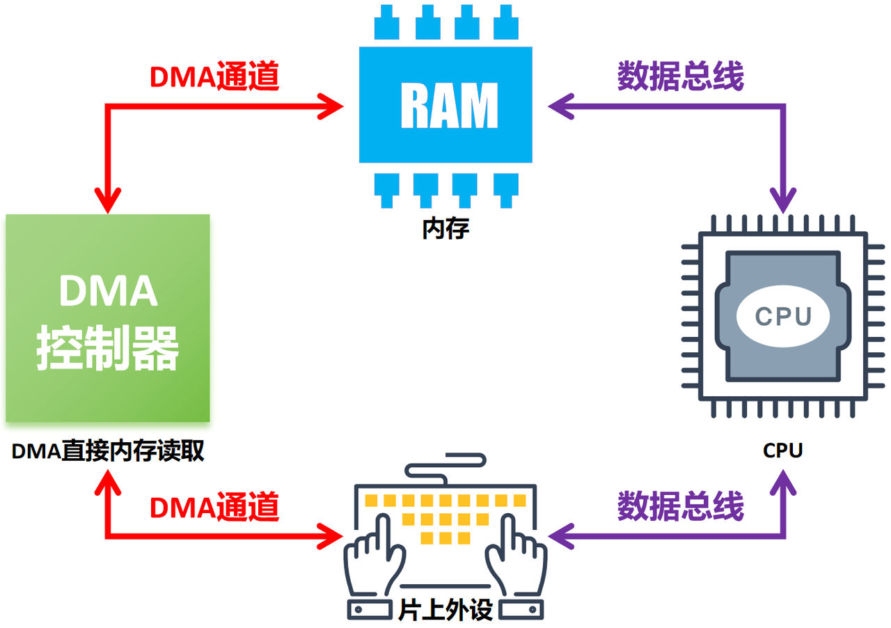
With DMA, peripherals and memory can transfer data without CPU involvement. Data transfers happen autonomously in the background so CPU resources are freed for other application tasks. Because the DMA controller communicates directly with memory and peripherals, data can be moved faster than under CPU‑driven software copy.
Compared with the workflow where the CPU reads data inside interrupt service routines triggered by peripheral interrupts, DMA drastically reduces the number of interrupt events related to data movement and lowers overall interrupt overhead.
- DMA Operating Principle
The DMA controller communicates directly with the system bus and manages data transfers between peripherals and memory. DMA works through the following sequence:
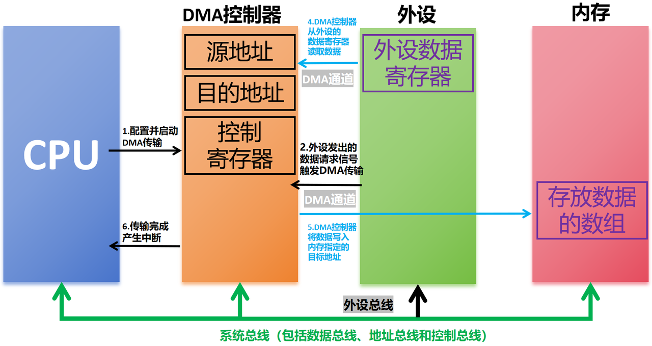
Simplified DMA data‑transfer sequence diagram
- DMA transfer request Before starting DMA, source address, destination address and transfer length must be configured. When a peripheral (UART, ADC etc.) needs data movement, it asserts a DMA transfer request. The CPU configures and enables DMA; actual data movement is then taken over by the DMA controller, which temporarily takes ownership of the system bus.
- DMA data transfer Using the system bus, the DMA controller moves data from source (peripheral or memory) to destination (memory or peripheral). This operation proceeds in background without CPU intervention over dedicated DMA channels. Note: DMA channels rely on the system bus.
- Interrupt notification Once the DMA transfer completes, the DMA controller sends an interrupt signal to the CPU to signal finished operation. System‑bus ownership is returned to the CPU, which can then process the transferred data without spending cycles on byte‑by‑byte copying.
DMA channels offload data‑movement work so the CPU is not overloaded. Without DMA, the CPU uses the system bus to send instructions and data toward peripheral buses, then copies every single item into target buffers. Bus operations block the CPU and prevent other tasks from running until finished.
CPU, DMA and other peripherals share the same system bus. When both CPU and DMA attempt bus access at the same time, bus contention occurs. An arbiter resolves conflicts and grants bus access based on task priority, urgency and system state.
DMA transfers also introduce potential pitfalls such as cache‑coherency issues. On MCUs equipped with cache (STM32 F7, U5, H7 families etc.), the CPU normally accesses cache instead of physical RAM to speed‑up memory operations. However, the DMA controller talks directly to RAM and bypasses CPU cache entirely.
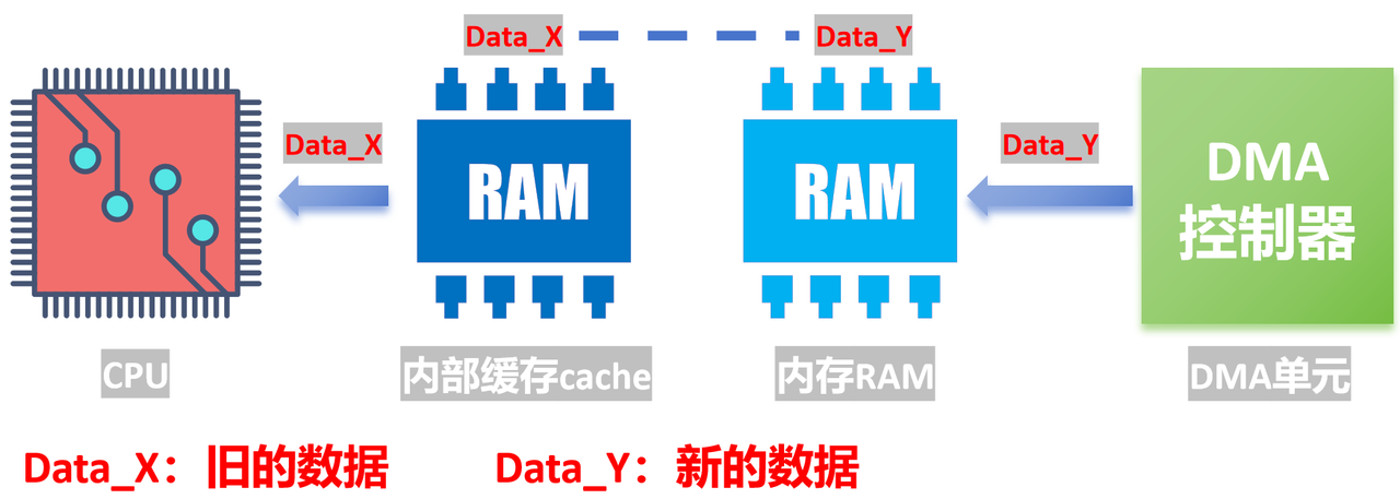
DMA cache‑coherency conceptual diagram
Two main failure modes arise:
Stale data The CPU modifies values inside cache but those modifications are not flushed back into RAM. DMA reads the outdated RAM copy. Example: the CPU modifies memory location X inside cache; subsequent writes only update the cached copy. If cache content is not written‑back to RAM before DMA reads X, DMA receives stale data.
Data inconsistency Conversely, when DMA writes new values into RAM but the CPU cache is not invalidated, the CPU still reads old cached values and obtains incorrect data.
Common mitigation strategies for MCU cache‑coherency problems:
Disable cache Cache can be turned off before DMA operations to eliminate coherency risks. This reduces overall performance because every memory access must go directly to RAM.
Cache Clean and Cache Invalidate operations
Cache Clean: Before DMA operations, force cache content write‑back into RAM so RAM matches cache state.
Cache Invalidate: After DMA completes, mark cache entries as invalid. Subsequent CPU reads fetch fresh data from physical RAM.
Use non‑cacheable memory regions Many MCUs allow marking selected memory ranges as non‑cacheable. Place DMA buffers inside these regions to avoid cache‑coherency risks.
Use dedicated DMA memory regions Some MCUs provide special memory segments reserved exclusively for DMA traffic, eliminating conflicts with CPU cache. Always perform DMA transfers from these dedicated areas when available.
- DMA Transfer Types
DMA is categorized by data‑movement direction:
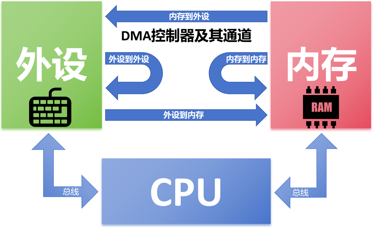
Memory‑to‑Memory transfer DMA copies blocks of data from one memory region to another. Typical use‑cases: fast frame‑buffer swapping for image/video, high‑speed forwarding of network packets inside RAM.
Peripheral‑to‑Memory transfer DMA writes peripheral‑generated data directly into memory without CPU intervention. Examples: reading data from SD‑card / NAND‑Flash into RAM; moving ADC sensor samples directly into memory buffers.
Memory‑to‑Peripheral transfer DMA pushes data stored inside memory out to peripherals. Examples: streaming audio/video samples from RAM to DAC or display; sending pre‑processed data over UART / SPI.
Peripheral‑to‑Peripheral transfer Used for copying data between peripherals, peripheral‑to‑peripheral data conversion / synchronization, accelerating encryption‑decryption workflows. Examples: copy data from SD‑card to NAND‑Flash; route ADC sampled data via DMA straight to DAC for analog output; output dual‑channel audio streams from different peripherals.
- DMA Transfer Modes
DMA controllers commonly support multiple operating modes:
Single Transfer Mode Only one data unit (byte or word) is moved per transaction. DMA releases bus ownership after each transfer so CPU or other masters can access the bus. Suitable for mixed workloads where bus sharing is required: e.g. running CPU application tasks together with small‑chunk peripheral transfers.
Burst Transfer Mode After acquiring bus ownership, DMA moves a contiguous block of data while holding the bus until completion. Suitable for high‑throughput scenarios such as large‑file copying from storage or high‑speed camera frame capture, where maximum transfer speed is prioritized and temporary bus blocking does not break critical tasks.
Circular Buffer Mode DMA repeatedly transfers data inside a pre‑allocated circular buffer. Ideal for continuous streaming workloads such as data logging, continuously filling sensor sample buffers.
Auto‑Request Mode DMA automatically triggers repeated identical transfers. Suited for periodic data acquisition: e.g. temperature sampling every 100 ms, UART data transmission every 50 ms.
- DMA Architecture
Major building‑blocks of an MCU DMA subsystem:
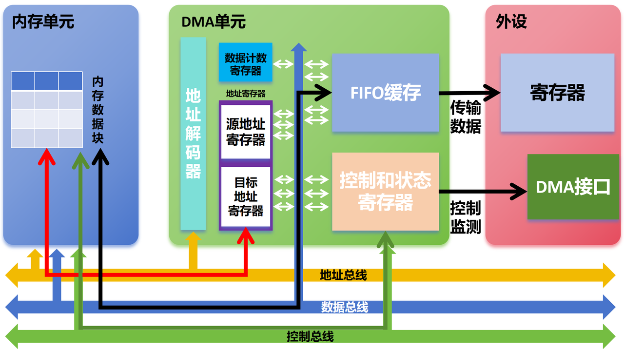
Block diagram of typical MCU DMA unit
DMA Channels A DMA controller provides multiple independent DMA channels. Each channel can be configured separately for different peripherals or memory‑to‑memory operations. Multiple streams can run concurrently with configurable priority levels. When several channels request bus access simultaneously, higher‑priority channels gain access first.
Address Registers
Source Address Register (SAR): Holds source read address; may point to peripheral register or memory location.
Destination Address Register (DAR): Holds target write address; may point to peripheral register or memory location.
Address increment / decrement capability: On most MCUs, DMA hardware can automatically increment or decrement address pointers after each transfer. Example: advance pointer from 100 → 101 or step backwards from 200 → 199. This handles large contiguous blocks (file buffers, image frames) without repeated software re‑configuration and improves throughput.
Data Registers
FIFO buffer: Temporary storage for in‑flight DMA data. Enables continuous streaming and reduces latency between request and actual transfer.
Data Counter Register (DCR): Stores remaining transfer count in bytes or words. Transfer finishes when counter reaches zero; DMA either halts the channel or raises completion notification.
Transfer‑Size Control: Configurable transfer width (8‑bit, 16‑bit, 32‑bit). Matches data format of peripherals and memory to prevent misalignment and corruption. For example an 8‑bit peripheral cannot accept 16‑bit wide transfers.
Control Registers
Channel Control Register (CCR): Configures channel behaviour: start / stop operations, priority level, trigger‑event selection.
Interrupt Control: DMA can generate interrupts on transfer completion, transfer errors or partial‑transfer milestones. Upon receiving interrupt, CPU executes corresponding interrupt handlers such as notifying application code or triggering error‑recovery logic.
Triggers
Hardware trigger: Transfer is started automatically by peripheral hardware events. Examples: ADC finish‑of‑conversion event, UART byte reception, camera frame end signal. Peripherals assert trigger signals to wake‑up DMA.
Software trigger: DMA transfer can be manually initiated by writing values into control registers from application software.
DMA Arbiter
Bus arbitration: DMA shares the system bus with CPU and other bus masters. Arbiter manages bus access among DMA channels to guarantee stable and efficient system operation.
Arbitration policies: Supports fixed‑priority and round‑robin (cyclic) priority schemes to determine bus‑access ordering among competing channels.