


[2.PNG](http://openwrite.cn/uploads/21597/63488/97e64a17-03bb-4bb2-be40-30b2ce3af7eb.png)[3.PNG](http://openwrite.cn/uploads/21597/63488/65120c63-537f-41aa-abe4-59cd60e71fdd.png)[4.PNG](http://openwrite.cn/uploads/21597/63488/046e8142-19d8-481b-b207-a86dfa02d961.png)[5.png](http://openwrite.cn/uploads/21597/63488/b0e86d46-1d53-4641-a268-0300a2f91364.png)[6.png](http://openwrite.cn/uploads/21597/63488/05ecbc7b-f65b-46a4-b3a9-c0eb0d0db091.png)[7.png](http://openwrite.cn/uploads/21597/63488/a37dc24d-a13e-42dd-87cd-221a30b51cec.png)[8.png](http://openwrite.cn/uploads/21597/63488/0c99ae69-0a9d-4994-a24c-7095f1a3fdaf.png)[9.png](http://openwrite.cn/uploads/21597/63488/f62bb6bb-c623-4e37-8556-57baab811117.png)[10.png](http://openwrite.cn/uploads/21597/63488/417f0c0f-f72a-40e9-bdaf-645bd858b3a0.png)[11.png](http://openwrite.cn/uploads/21597/63488/603f982b-51b9-4798-885b-0f33ea4b3979.png))
Demystify USB Protocol: From History, Architecture to Endpoint Communication (Part 2)
USB adopts differential signals, NRZI and bit‑stuffing. Its packets, frames and transactions realize standard serial communication.
2.USB Data Transmission and Packets
1.1 USB Data Transmission
USB is an asynchronous serial communication method (USB 2.0 protocol adopts half‑duplex communication). Only one packet can be transmitted on the bus at a time. Data on the USB bus is little‑endian, meaning the least‑significant bit is sent first, followed by the most‑significant bit.
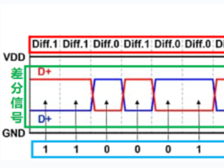
The USB data signal lines use a pair of differential signals: D+ and D‑, which can represent two types of data:
Diff.1: When D+ is high level and D‑ is low level, this state is called "Differential 1"
Diff.0: When D+ is low level and D‑ is high level, this state is called "Differential 0"
Diff.1 and Diff.0 are physical‑layer differential signals of USB. For data representation, NRZI (Non‑Return‑to‑Zero‑Inverted) encoding is adopted:
When the NRZI‑encoded data is '0': The differential signal level flips, and the differential data changes
When the NRZI‑encoded data is '1': The differential signal level remains unchanged, and differential data stays the same

Important note on the relationship between differential signals and NRZI‑encoded data: When USB transmits logical "data 0", the physical layer outputs "diff.0". However, a "diff.0" signal does not necessarily stand for logical "data 0"; it may also represent a level flip within NRZI encoding.
Continuous transmission of many '1's keeps the signal level unchanged for a long time, which harms clock synchronization between host and device (USB has no dedicated clock wire). Therefore, the USB protocol defines the following mechanism:
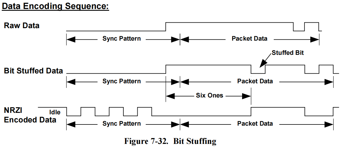
- Bit Stuffing:
- When six consecutive "1"s appear on the USB data line, a "0" bit is forcibly inserted as a synchronization signal
- Bit stuffing guarantees level transitions. Receivers use these sync codes to align their receive clock with the transmitter
- Receiver Bit Destuffing:
- The receiver identifies and removes those stuffed "0" bits during decoding
- This operation is implemented by hardware chips and transparent to users
- The original data sequence can be restored
1.2 USB Packets
On the USB bus, the basic unit of data transmission is a Packet. Each packet consists of multiple fields:
SYNC (Synchronization Field)

Helps the receiver synchronize clock and data
Composed of a sequence of data‑0 bits followed by one data‑1 bit. Consecutive data‑0 bits produce continuous level transitions on the bus
Based on NRZI encoding, the receiver synchronizes its clock with the sender according to the frequency of level flips
Full‑/low‑speed devices send 7 zero bits; high‑speed devices send 31 zero bits
PID (Packet Identifier) Identifies packet types such as TOKEN, DATA, HANDSHAKE, etc.
PID is 8‑bit long. Only the lower 4 bits carry actual type information; the upper 4 bits are the complement of lower 4 bits for error‑checking.
Other Fields Depending on packet type, fields such as address, data payload, and checksum may be included.
EOP (End of Packet)
Marks the end of a packet
For full‑speed / low‑speed devices: hold both D+ and D‑ low for two bit times (two‑bit SE0 signal)
For high‑speed devices: uses a bit‑stuffing error signaling pattern. Host checks CRC:
CRC pass → valid EOP
CRC fail → bit‑stuffing error
Every packet starts with SYNC and PID, and ends with EOP.
Based on usage, USB defines several packet categories:
Token Packet
Carries address and endpoint information to identify the target for transmission Includes OUT, IN, SETUP and other subtypes
Data Packet
Transmits actual payload data
Includes DATA0 and DATA1
Handshake Packet
Reports transmission status, e.g. ACK, NAK, STALL
Special Packet Includes SOF, RESET, SPLIT for synchronization, reset and other special functions
Below is a detailed introduction for each packet type.
1.2.1 Token Packet
All USB transactions are initiated by the host sending a Token Packet.
Token Packet fields:
SYNC‑Synchronization Field:
Synchronizes receiver clock and data
PID‑Packet Identifier: Indicates token type: OUT, IN, SOF or SETUP
ADDR‑Device Address: Specifies target device address
ENDP‑Endpoint Number: Specifies target endpoint number
CRC5‑5‑bit Cyclic Redundancy Check: Verifies integrity of preceding fields
EOP‑End of Packet: Marks token packet termination
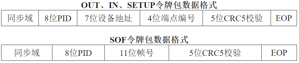
Among the four token types above, OUT, IN and SETUP share identical format. SOF token has slight differences. CRC5 checks data fields after PID only.
OUT Token Packet:
Host informs the device
that outgoing data is coming
Device prepares for data reception
IN Token Packet:
Host requests data from the device
Device prepares to transmit data
SETUP Token Packet:
Similar to OUT, tells device incoming packet is on the way
Subsequent packet must be DATA0 and directed to the control endpoint
SOF (Start of Frame) Token Packet:
Periodically sent by host for host‑device synchronization
1.2.2 Data Packet
Fixed structure: SYNC + PID, followed by N‑byte payload, then 16‑bit CRC16 and EOP.
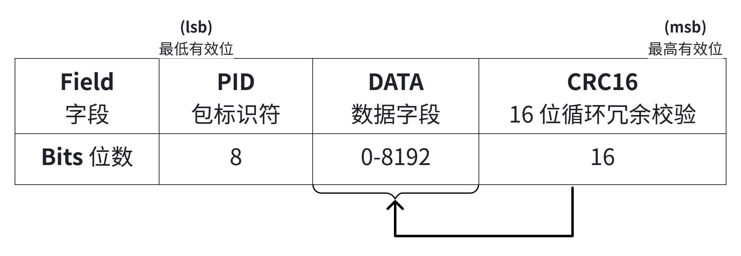
PID can be DATA0 or DATA1. Alternating DATA0 / DATA1 improves transmission reliability, defined since USB1.1:
- Alternation of DATA0 and DATA1:
- Host and device alternate between DATA0 and DATA1 during transfers
- Helps receiver identify packet sequence
- Fault‑tolerance mechanism:
- Mismatched packet type detected by receiver indicates prior transmission error
- Triggers retransmission to boost reliability
- Packet‑type toggle state machine:
- Both host and device maintain a toggle state machine
- Toggle to the other type upon successful send or receive
USB2.0 adds DATA2 and MDATA for high‑speed split‑transaction and high‑bandwidth isochronous transfer:
DATA2 Packet
Used for High‑Speed Split Transaction
Applied in split data transfer between host and high‑speed devices Improves interoperability
MDATA Packet
Used for High‑Speed High‑Bandwidth Isochronous transfer
Allows multiple packets within one microframe
Suits latency‑sensitive, high‑bandwidth scenarios
1.2.3 Handshake Packet
Handshake Packet contains SYNC, PID and EOP to acknowledge transfer results.
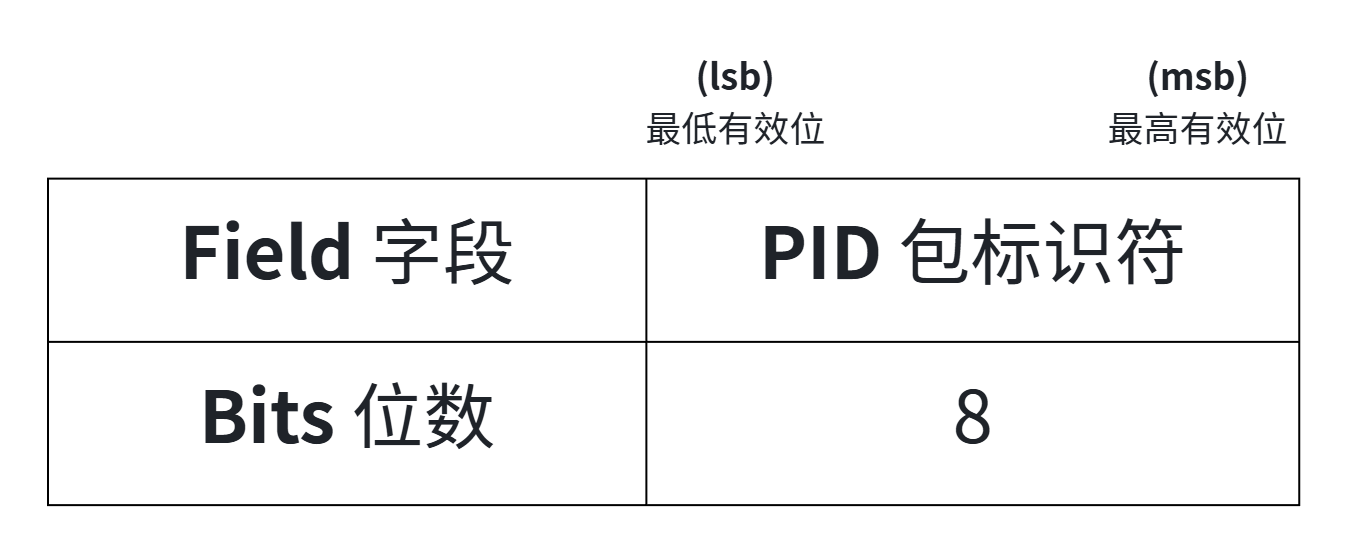
Common handshake PID types:
ACK: Host / device has received data successfully
NAK: Device reports data is not ready
STALL: Endpoint is stalled
NYET: Device received current data OK but cannot accept further data
1.2.4 Special Packet
Special packets implement dedicated functions:
SOF (Start of Frame)
Periodically transmitted by host
For host‑device synchronization
Carries millisecond‑based frame number
RESET
Sent by host to reset USB device
Device enters default state upon receiving RESET
SPLIT
Enables split transactions between high‑speed host and full/low‑speed devices Host sends SPLIT packet before actual data transfer
ERR
Signals error within high‑speed split transaction
PING
Host queries readiness of high‑speed device for reception
Device replies ACK or NAK for high‑speed flow‑control
2.USB Frames and Transactions
The top‑level timing unit of USB transmission is a Frame, lasting 1 ms. A frame starts with SOF packet and contains one or more transactions. SOF marks frame boundary.

The basic interactive unit is a Transaction. A complete transaction consists of three phases:
- Token Phase
- Host sends Token Packet specifying target device and endpoint
- Token types: IN, OUT, SETUP define transfer direction and semantics
- Data Phase
- If payload exists, host or device sends Data Packet
- Packet size is bounded by endpoint maximum packet size
- Direction: IN (device‑to‑host) or OUT (host‑to‑device)
- Status Phase
- Receiver replies Handshake Packet indicating success or failure
These three phases form one full transaction. Host applies different transaction styles (control, bulk, interrupt, isochronous) matching endpoint characteristics. Based on device descriptors, host schedules transactions fairly to avoid conflicts. This phased‑transaction architecture supports diverse data‑traffic patterns and delivers stable performance.
Relationship among Frame, Transaction and Packet:
Frame provides time‑synchronization and scheduling framework
Transaction is the basic interaction unit executed inside one frame
Each transaction is built from multiple packets; packet is the minimum transmission unit