



DDS Direct Digital Synthesis Explained: Principle, Modules & Frequency Equation
DDS principle & formula overview
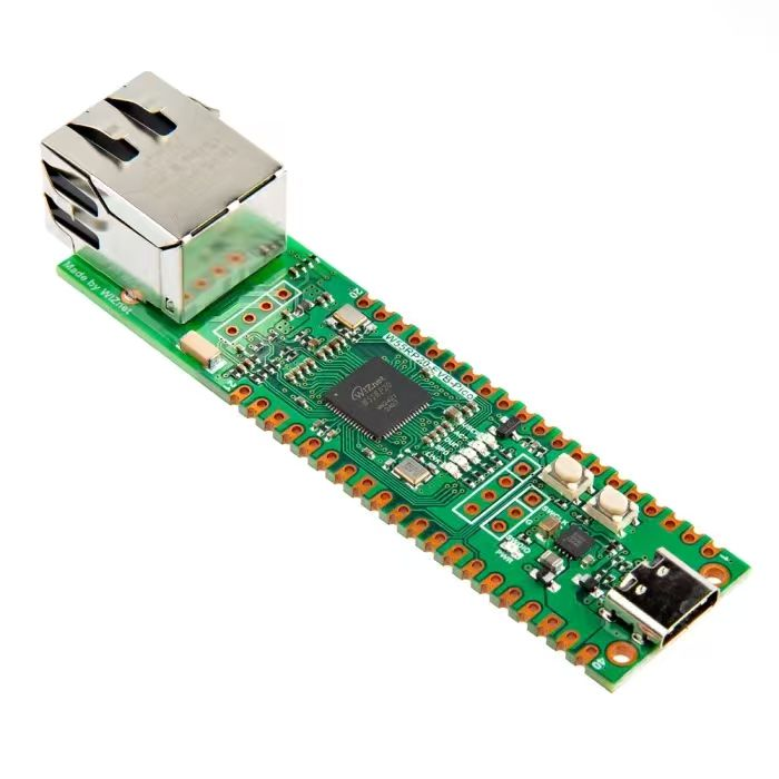
In practical applications, we often want to output analog signals such as sine waves or square‑waves of defined frequency, rather than discrete voltage values. We can use a DAC to output pre‑defined digital signal patterns. However, waveforms directly generated by a DAC usually have fixed or constrained frequency, amplitude and other characteristics. To change the waveform, new digital data must be regenerated and loaded. This process is relatively slow and poorly‑suited for scenarios requiring real‑time dynamic waveform adjustment.
Under such circumstances we can use a DDS signal generator. Direct Digital Synthesis (DDS) is an efficient signal‑synthesis technology for generating arbitrary waveforms including sine waves, square waves, sawtooth waves and triangular waves. It is widely used in signal generators, modems, radio‑communication equipment and many other fields. DDS features high frequency resolution, fast frequency‑tuning speed, low phase noise and great flexibility for frequency, phase and amplitude control.
Waveforms can be adjusted at runtime by changing DDS input parameters. DDS fits applications requiring frequency synthesis, modulation or phase adjustment such as wireless communications and radar systems. In fact, the DAC is part of a DDS signal generator. DDS generates digital phase values and converts them into waveform amplitude values, while the DAC converts these digital amplitude values into analog signals.
An analogy helps illustrate their relationship:
DDS acts like a band conductor. It determines rhythm, tonality and variation for the whole piece of music. Gestures and sheet‑music tell performers what notes to play and when. Similarly, DDS sets frequency and phase of output waveforms using digital logic.
DAC acts like musical instruments. They produce actual musical sound following the conductor’s directions. In the same way, the DAC translates digital signals into analog waveforms for loudspeakers or other analog‑domain equipment.
The core building‑blocks of a DDS signal generator are a digital phase accumulator, waveform memory (Look‑Up Table, LUT), and a Digital‑to‑Analog Converter (DAC):
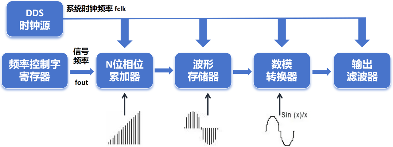
Function of each component:
Clock Source Provides clock signal for the DDS system, normally a stable high‑frequency clock. Higher clock frequency improves DDS output frequency resolution and waveform quality.
Phase Accumulator Binary adder, typically 32‑bit or wider. It adds the Frequency Control Word (FCW) to the current phase value on every clock cycle.
Frequency Control Word (FCW) Register Stores the frequency control word which sets output‑signal frequency. Output frequency can be changed rapidly by modifying FCW.
Waveform Memory (Look‑Up Table) Holds pre‑computed digital waveform samples, most commonly sine‑wave points. Memory size and stored sample content determine supported waveform types and generation precision.
DAC (Digital‑to‑Analog Converter) Converts digital waveform samples into analog‑domain signals.
Output Filter Filters DAC output to remove high‑frequency components and noise, yielding clean analog‑waveform output.
DDS operating workflow:
- Phase accumulation The main functional unit is the phase accumulator, a modulo‑N counter‑based module. It increments its stored value by a fixed step size on each clock cycle. This step size is defined by the Frequency Control Word (FCW).
Assume system clock frequency equals fclk. Output signal frequency fout is calculated with the formula:
$$ fout = \frac{FCW \times f_{clk}}{2^N} $$
Where FCW stands for frequency control word and N represents bit‑width of the phase accumulator.
Output from the phase accumulator is a phase value used as address index to fetch corresponding waveform sample from waveform memory.
- Waveform lookup
Waveform memory stores pre‑calculated waveform amplitude samples e.g. sine‑wave points. Output value from phase accumulator serves as memory address for reading the corresponding waveform data sample.
By mapping phase‑accumulator output onto memory addresses, DDS can generate waveforms at different phase offsets.
- Digital‑to‑analog conversion Digital waveform samples read from waveform memory are fed into the DAC, which converts them into analog signals and drives the output load.
- Output signal Final analog waveform is produced after filter processing.