Data Transceiver Practice: hardware Configuration, MicroPython Programming
This experiment realizes UART send & receive on Fengya No.1 board, with bytes decoding, LED prompt and verification using XCOM.
COMPONENTS
PROJECT DESCRIPTION
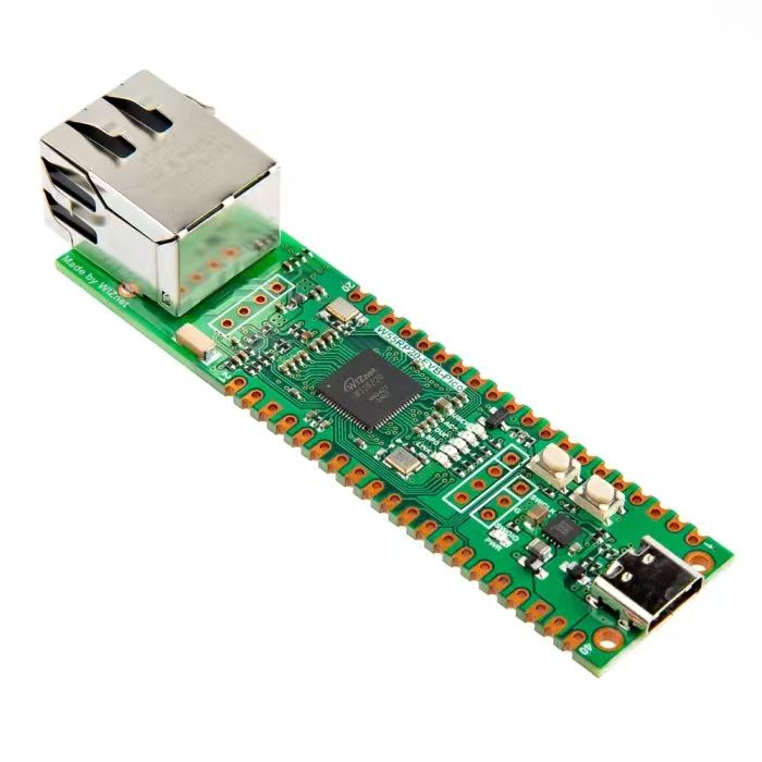
【Preliminary Note】The original hardware example in this article was written based on the RP2040. The actual hardware used in this hands-on demonstration features the W55RP20 as the main controller chip. The circuit logic and UF2 flashing operation principles are universally applicable, with only the main controller model differing. The original chip model mentioned in the circuit descriptions below is provided for reference purposes only.
Tweet
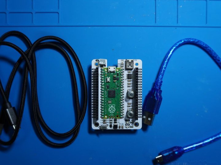
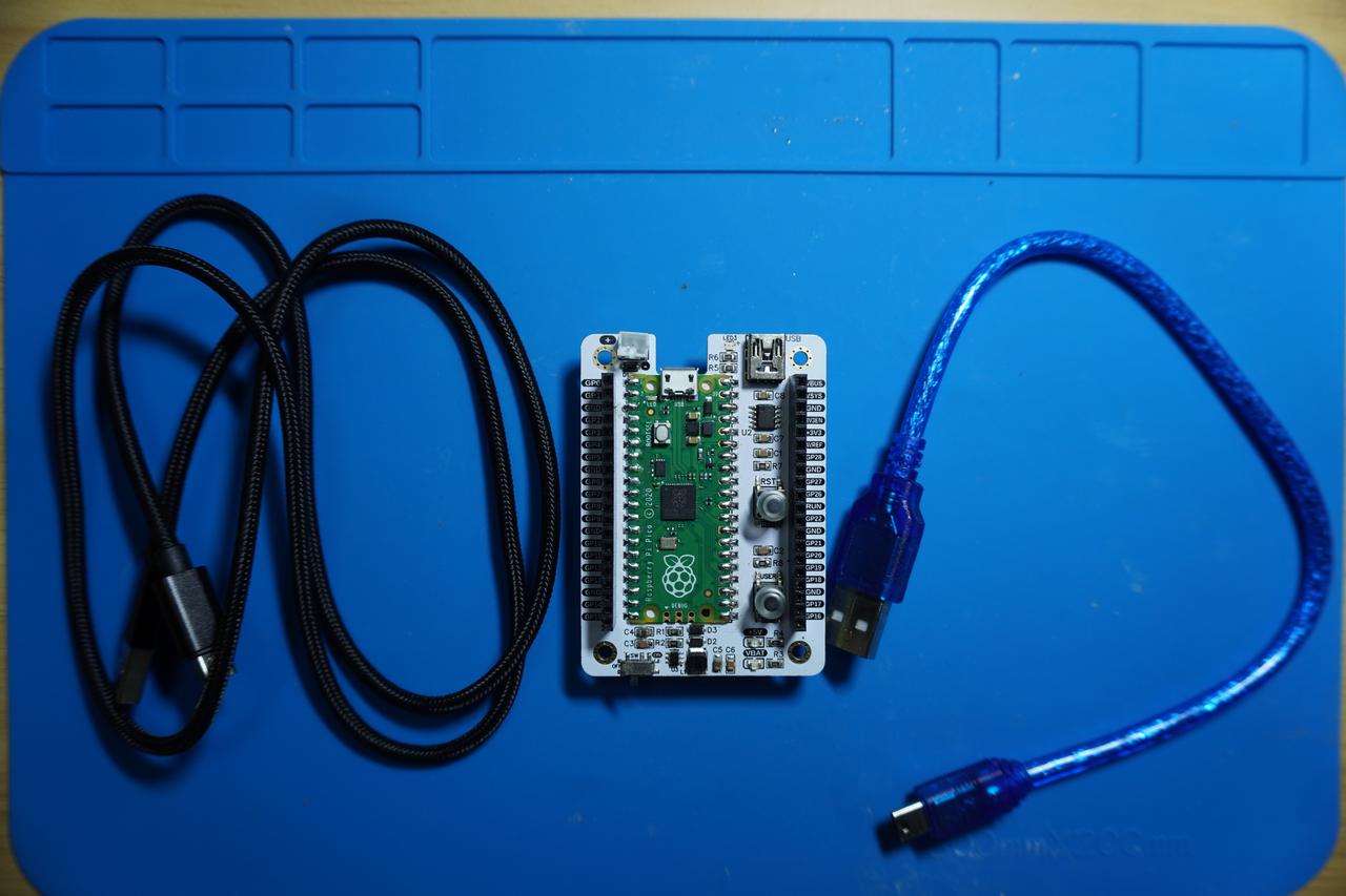
In the following experiment, we need to use a MiniUSB cable to connect the Fengya No. 1 Board - Universal Compatible Expansion Board 's UART0 to the USB port on it with the USB port on the computer:
In the following code, we have designed a program for implementing serial port (UART) data transmission and reception.
The sample code is as follows, located in the folder of the supporting materials: elegance-devkit v1\Demo\07 UART_ReadWrite:
In the above code, we have performed the following operations:
Initialization configuration: Configure the UART0 serial port, set the baud rate to 115200, configure GPIO0 as TX (transmit) and GPIO1 as RX (receive), set the timeout period to 100ms, and configure the GPIO25 pin as the LED control pin
Use while loop to implement serial data transmission and reception, send the string Hello, UART! each time and try to read data, decode and print the received data, meanwhile control the LED to turn on and off to indicate the receiving operation
When the number of data receptions reaches 10, exit the loop and call the LED_Blink function to make the LED blink continuously
Here, the data received via the serial port is of the bytes type (an immutable binary byte sequence). As an immutable data type, bytes is used to represent byte sequences, storing data in units of bytes with a value range of 0 to 255. The bytes type is similar to the string type (str), except that its character encoding is bytes (the raw representation of binary data) rather than Unicode characters. The bytes type is extremely useful in scenarios involving binary data processing, such as network communication, file reading and writing, and encryption and decryption.In Python, adding the prefix b before a string indicates the bytes type.
In the above program, we use the following code to decode the received immutable binary byte sequence and convert it into a string type:
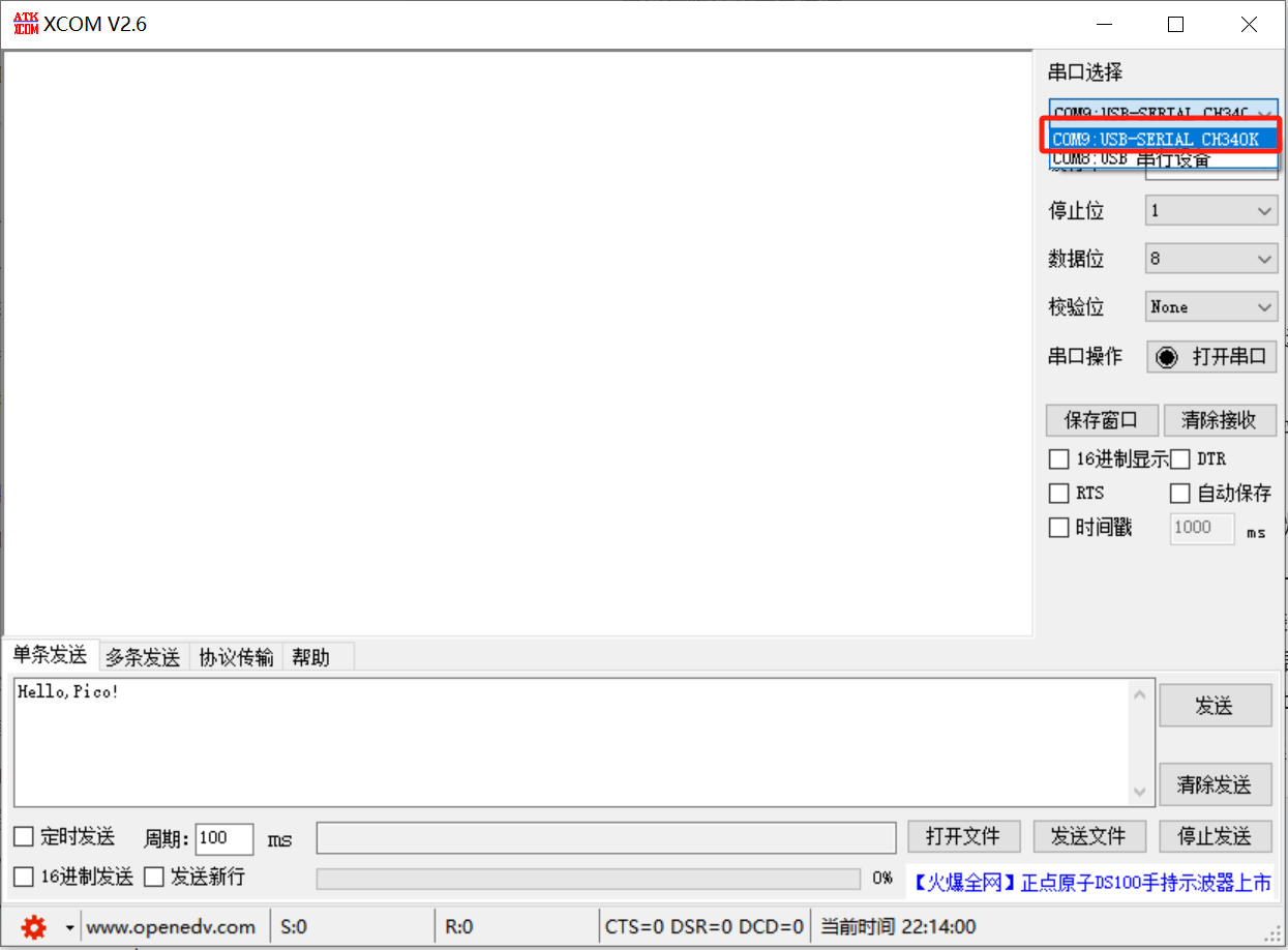
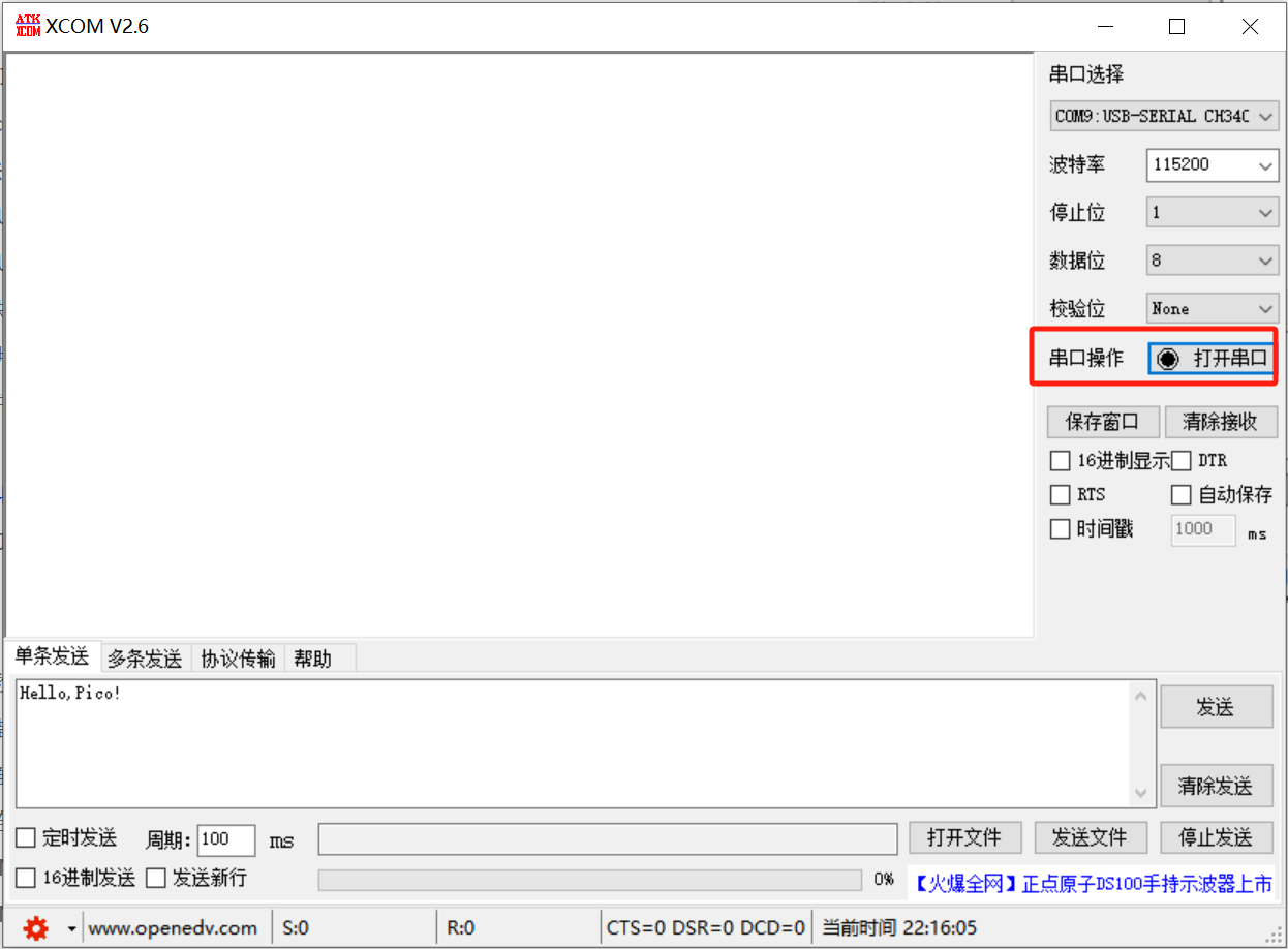
Open the XCOM software and select the COM port corresponding to the CH340K chip:
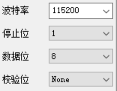
The serial communication parameters are consistent with those in the program:
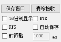
Keep the rest of the sending and receiving parameters as default:
Click to open the serial port:
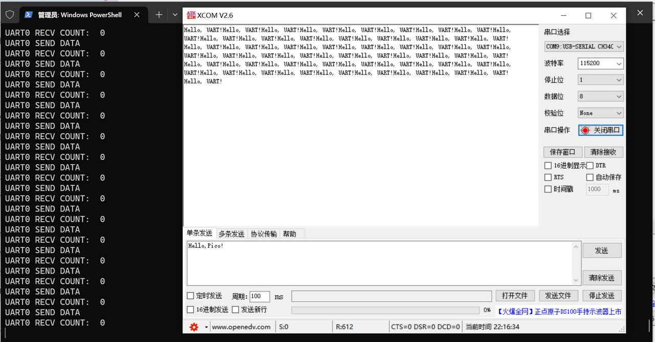
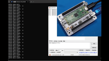
Burn the program, open the terminal, and the following content will be displayed:
As can be seen, when we do not perform any operation, XCOM software can normally receive the data sent by the Raspberry Pi Pico.
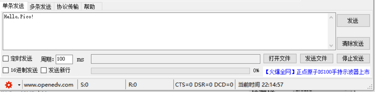
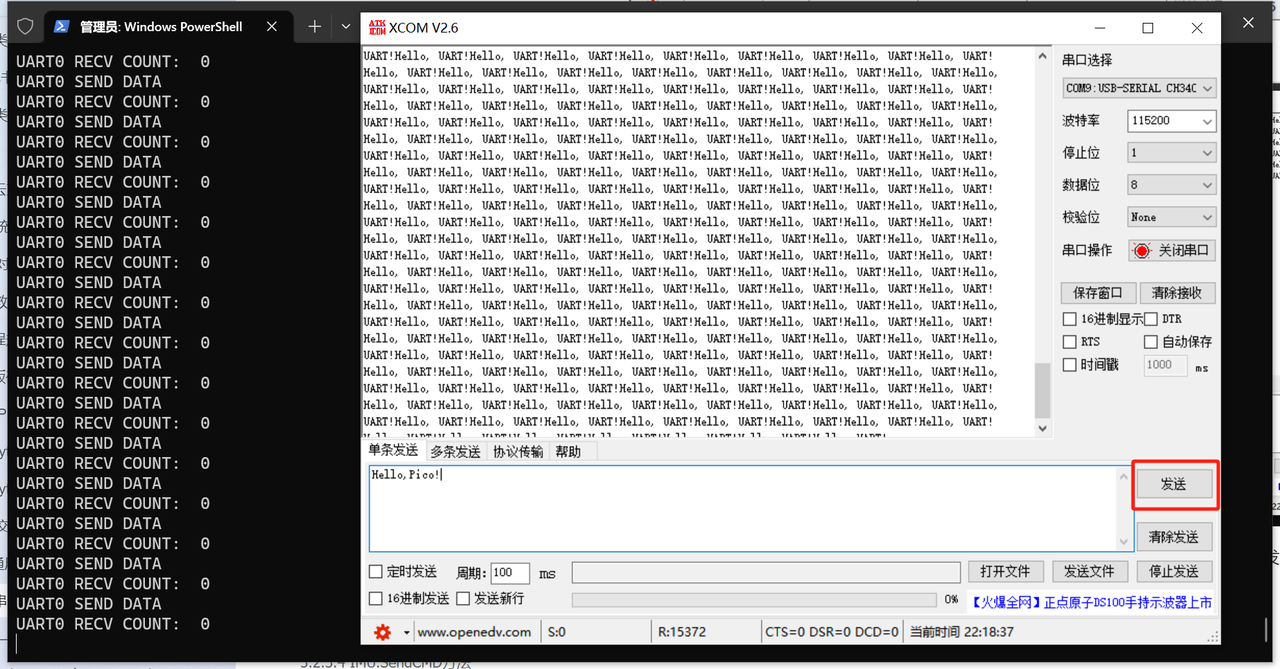
We try to send a string from the computer via the XCOM software Hello, Pico! to the Raspberry Pi Pico:
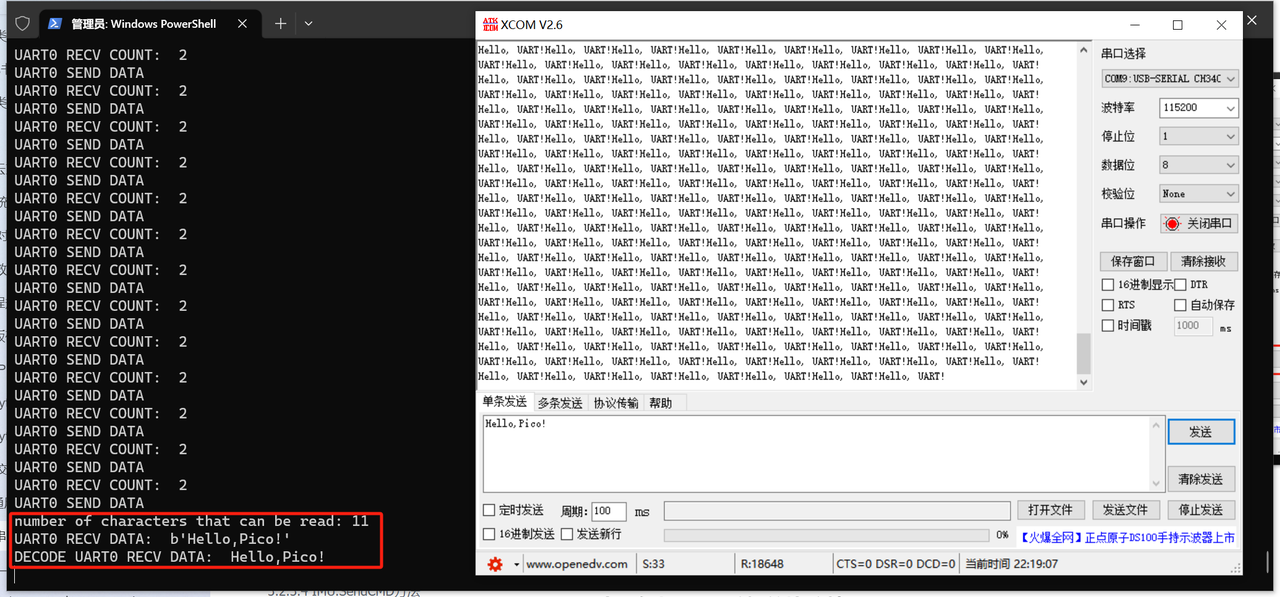
It can be seen that the terminal outputs the number of characters received via the serial port of the Raspberry Pi Pico, as well as the data before and after decoding:
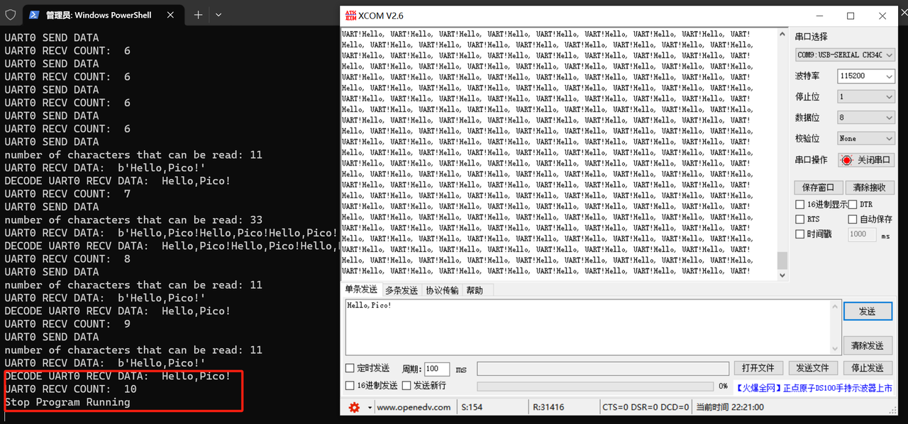
Meanwhile, each time a string is sent from the computer via XCOM software, the Raspberry Pi Pico 's onboard LED will blink once. After ten consecutive transmissions, the Raspberry Pi Pico stops receiving serial data, and its onboard LED keeps blinking continuously:
Additionally, when the Raspberry Pi Pico transmits and receives data via the serial port, Fengya No. 1 Board - Universal Compatible Expansion Board the serial port transmit-receive indicator on it LED3 will light up intermittently: