Bus Servo vs Digital Servo: Structure & Signal Principles Deep Dive
This content covers serial bus servo basics, LX-1501 protocol and a MicroPython SerialServo driver for servo control and data reading.
COMPONENTS
PROJECT DESCRIPTION
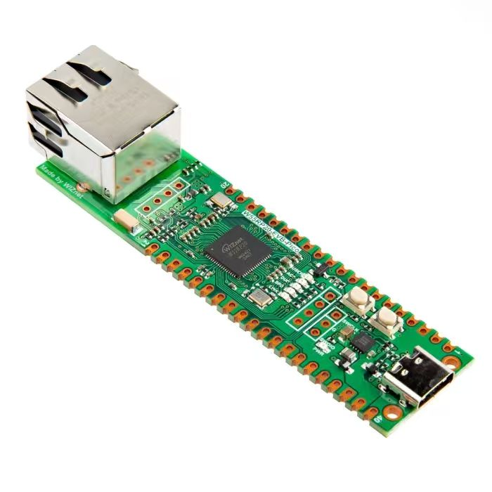
【Preliminary Note】The original hardware example in this article was written based on the RP2040. The actual hardware used in this hands-on demonstration features the W55RP20 as the main controller chip. The circuit logic and UF2 flashing operation principles are universally applicable, with only the main controller model differing. The original chip model mentioned in the circuit descriptions below is provided for reference purposes only.
1. Introduction to Serial Servos
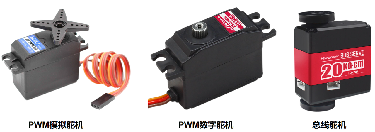
A servo motor is a position (angle) servo actuator, whose core function is to precisely control the rotation angle of the output shaft according to the input signal, and is widely used in scenarios such as robot joints, model aircraft control surfaces, and smart home robotic arms. In terms of technical iteration, servo motors have gone through the upgrade path of "PWM analog servo → digital servo → bus servo", and each generation is optimized around "control accuracy, communication efficiency, and function scalability".
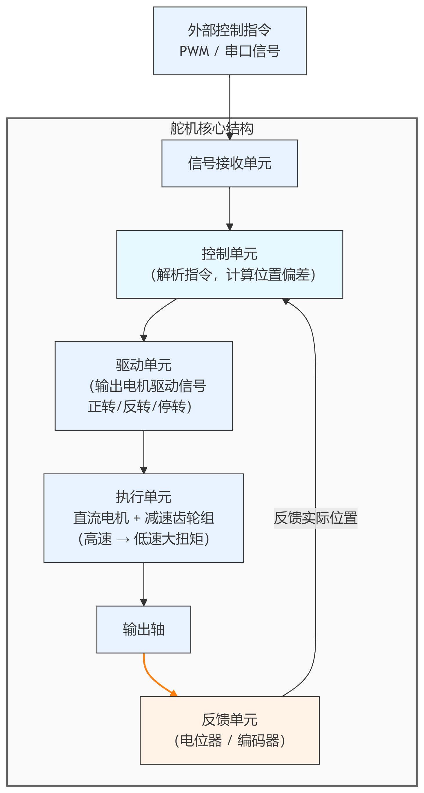
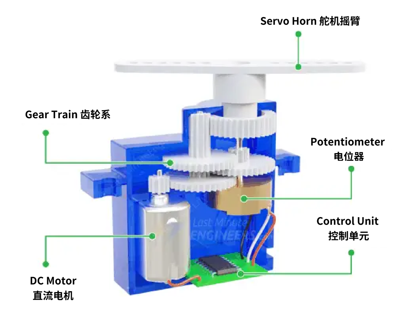
Regardless of the type of servo, its core structure consists of five major modules: signal receiving unit, Control Unit, drive unit, execution unit, and feedback unit, and the differences mainly lie in "signal form" and "the implementation mode of the Control Unit":
Signal receiving unit: Receives external control commands (PWM or serial port signals);
Control Unit: parses instructions and compares the deviation between the current position and the target position;
Drive Unit: Outputs motor drive signals (forward rotation / reverse rotation / stop) based on the deviation;
Execution Unit: Consists of a DC motor + reduction gear set, which converts the high-speed rotation of the motor into low-speed, high-torque rotation of the output shaft;
Feedback Unit: It detects the actual position of the output shaft via a potentiometer or encoder, and sends a postback to the Control Unit to form a "closed-loop control".
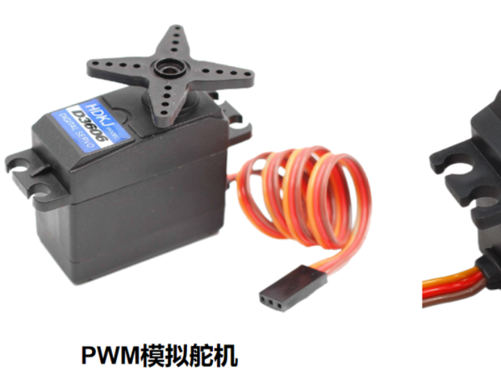
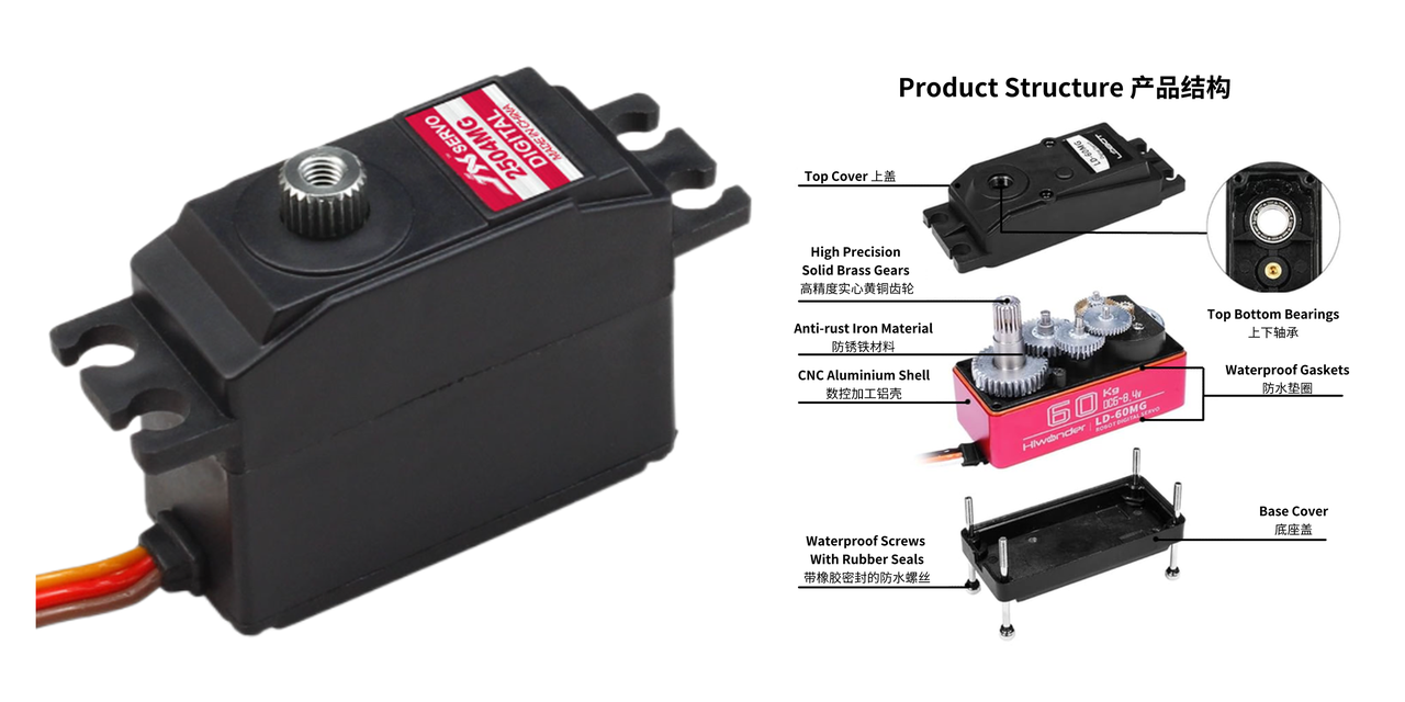
PWM analog servos are the most basic type of servo, which rely on analog circuits as their core to achieve closed-loop control. The Control Unit of an analog servo consists of analog circuits such as operational amplifiers, with no digital chips, featuring a simple structure:
However, PWM analog servos also have the drawbacks of poor control accuracy, slow response speed, no status feedback and weak anti-interference capability.
PWM digital servos are developed based on analog servos by incorporating an MCU (Micro Control Unit) and replacing part of the analog circuits with "digital circuits", which solves the problems of analog servos in terms of accuracy, anti-interference and response.
The control signal of the PWM digital servo is still a PWM signal (compatible with the control standard of analog servos), but its internal control logic is fully digitized:
The "operational amplifier" of the analog servo is replaced by "MCU + digital comparator";
The analog voltage signal from the potentiometer is converted into a digital signal by the ADC (Analog-to-Digital Converter), which is then sent to the MCU for precise comparison with the target angle.
However, PWM digital servos still rely on PWM simplex communication, which cannot postback status data; meanwhile, multi-servo control remains cumbersome, and just like analog servos, controlling one servo channel requires occupying one IO port of the MCU. The core breakthrough of bus servos lies in replacing PWM signals with "bus communication" to realize "two-way communication + bus control", which completely reconstructs the control logic of servos.
The main control unit obtains the current position and the target position to be reached of the servo through the transmission and reception of instruction packets. It is a form of closed-loop control. The feedbackable parameters include voltage, current, temperature, torque, speed, position, and whether the status of the servo is normal.
Common bus servos include the following models:
RS-485 Serial Servo Motor: Based on differential signal transmission, it features strong anti-interference performance and long transmission distance, making it suitable for industrial and research-grade robots.
TTL Serial Servo: Directly controlled via the UART of a microcontroller, it features simple wiring and low cost, and is commonly used in educational robots and open-source projects.
CAN bus servo: Adopting the CAN bus protocol, it features high reliability and strong scalability, and is widely used in automotive electronics and industrial robots.
Bus servos support independent address setting (e. g., configuring addresses 0 to 255 via DIP switches or commands), and multiple servos can share a single set of serial bus lines (TX transmission line, RX reception line, GND ground line):
When the host sends a command, the frame contains the "target servo address";
After all servos on the bus receive the command, they first parse the address: only the servo whose address matches the received address will execute the command, while all other servos will ignore it.
When the servo performs postback of data, the frame contains its own address, allowing the host to identify the data source.
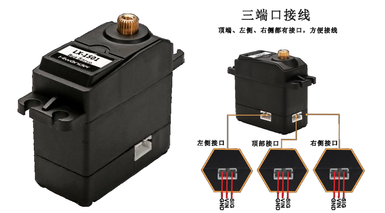
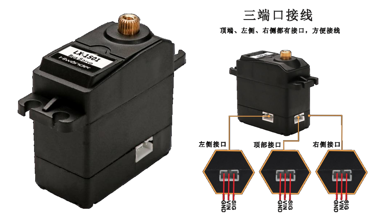
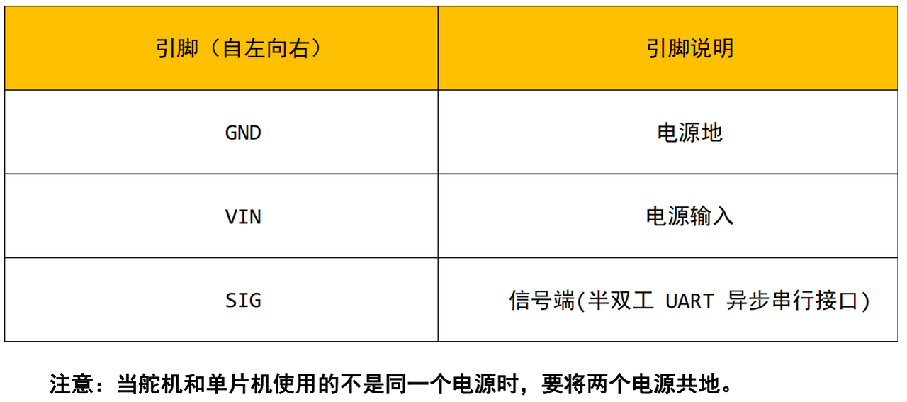
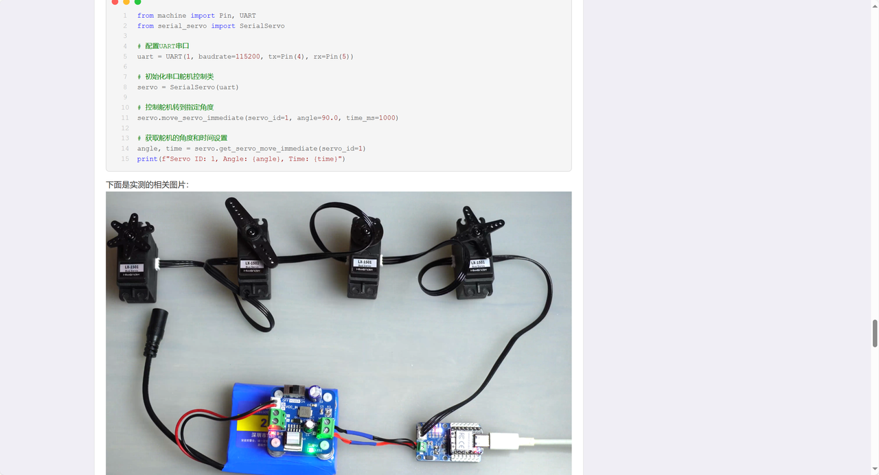
Next, taking the LX-1501 bus servo motor from Hiwonder as an example, we will explain how to read, write and control the serial servo motor through a custom serial protocol frame. The Hiwonder LX-1501 intelligent bus servo motor integrates servo drive, motor and bus servo signals, receives command control through the half-duplex UART asynchronous serial interface, and has a serial baud rate of 115200. Users can send commands according to the Communication Protocol to realize servo rotation and information reading, and can also switch to the stepping motor mode.This servo motor supports multi-unit series connection (with a theoretical maximum of 253 units in series), and is widely used in robot projects requiring closed-loop control such as bionic robot joints.
LX-1501 has the following key parameters:
Power and Performance: Rated operating voltage: 7.4V (range: 6 - 8.4V), stall torque: 17kg. cm, rotation speed: 0.16s/60°(at 7.4V), control angle range: 0 - 1000 (corresponding to actual 0°~240°), accuracy up to 0.3°;
Functions and Protections: Supports power-off storage of user settings and angle readback, can feed back parameters such as temperature, voltage and position, and features stall protection and over temperature protection;
Configuration and Specifications: The default ID is 1 (configurable within 0-253), it adopts metal gears, comes with a 20cm PH2.0-3P connector (cable length optional), measures 40×20.0×40.5mm in dimensions and weighs 58g.
The following points should be noted during use:
Power Adaptation: Select a stable power supply within the range of 6-8.4V; overvoltage will burn out the steering gear, while undervoltage will fail to drive it properly.
ID Setting: The factory default ID is 1, which needs to be preset as required before use. When setting the ID, connect the servo motor alone (to avoid all servos being set to the same ID when connected in series), and then connect them in series after the setting is completed.
Mechanical and Heat Dissipation Protection: Do not forcibly twist the servo arm or servo disc after power-on to avoid damaging the internal structure; the servo will generate heat after continuous operation, so it needs to be cooled in time to prevent overheating from affecting its performance and service life.
Load limit: During continuous rotation, the load shall be ≤ 1/3 to 1/5 of the stall torque (stall torque refers to the maximum torque of the servo when it cannot rotate; excessive load will increase energy consumption and reduce efficiency).
For additional details, please refer to the materials we provided; no further elaboration will be given here.
2. Hiwonder Serial Bus Servo Communication Protocol Introduction
The bus servo Communication Protocol serves as the "language specification" for interaction between the driver and the servo, and all control commands (such as rotation angle adjustment and temperature reading) as well as status feedback must be transmitted in accordance with the protocol format. This protocol is based on half-duplex UART asynchronous communication, supports series control of up to 253 servos, has a fixed baud rate of 115200bps, and realizes functional control through the core process of "command frame packaging - transmission - response frame parsing".
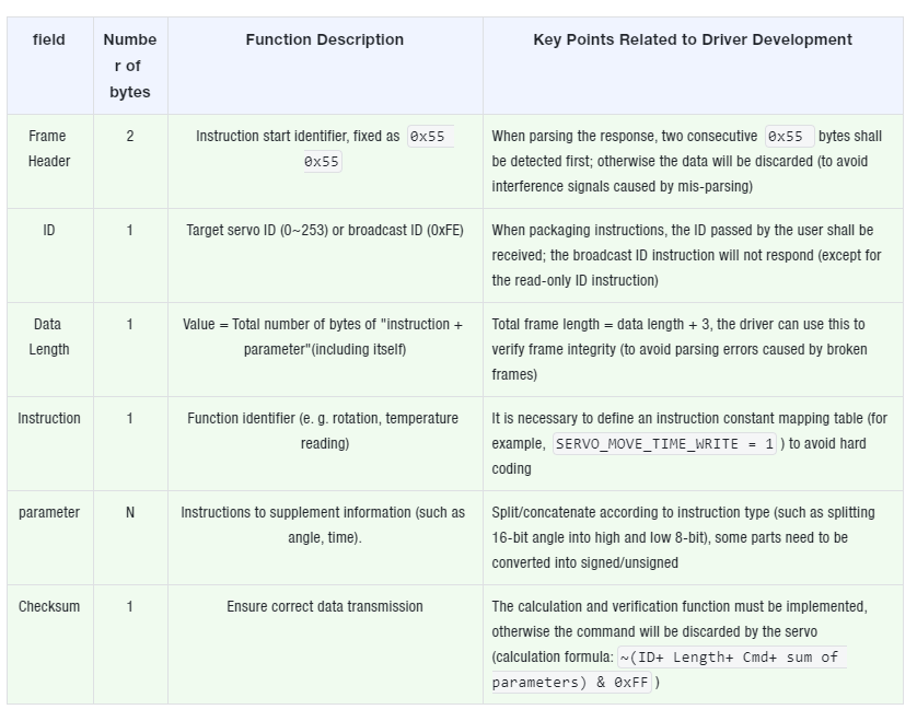
All commands and responses follow a unified frame structure, and the driver shall process data in the order of fields to ensure that the servo can be recognized and the response can be parsed:
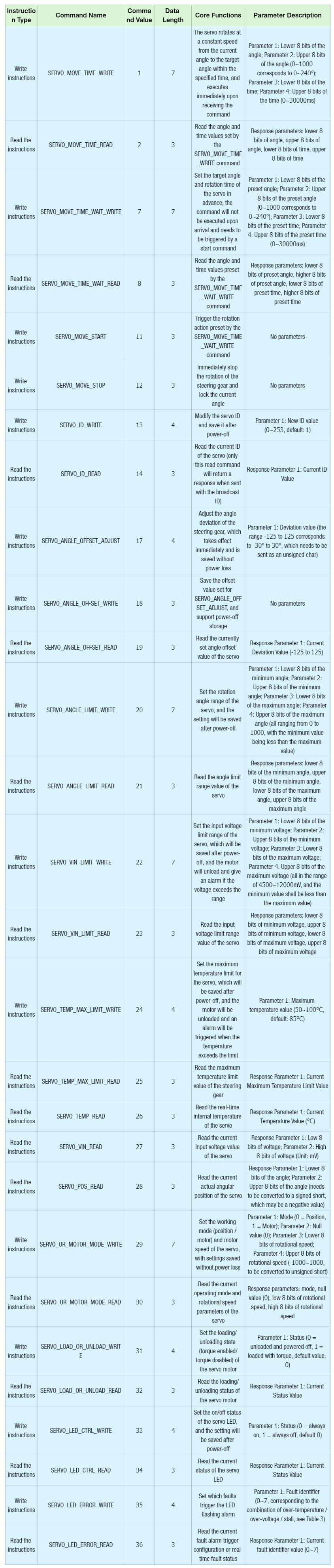
Protocols are categorized by function into "write commands (configuration/control)" and "read commands (status acquisition)":
Write Instruction: Suffix _WRITE, with parameters (e. g., angle setting), no response after execution (no waiting required after the driver sends the instruction);
Read Instruction: Suffix _READ, no parameters (e. g. for temperature reading), a response will be returned after execution (the driver shall receive and parse it immediately).
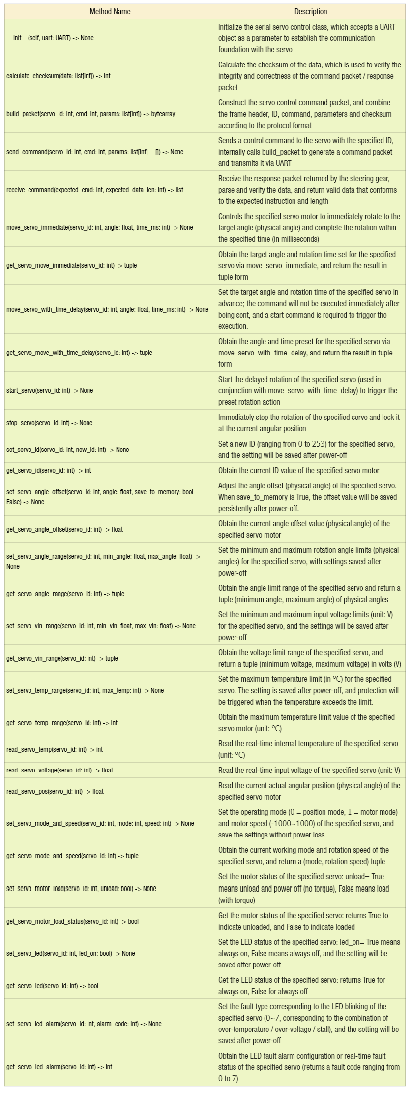
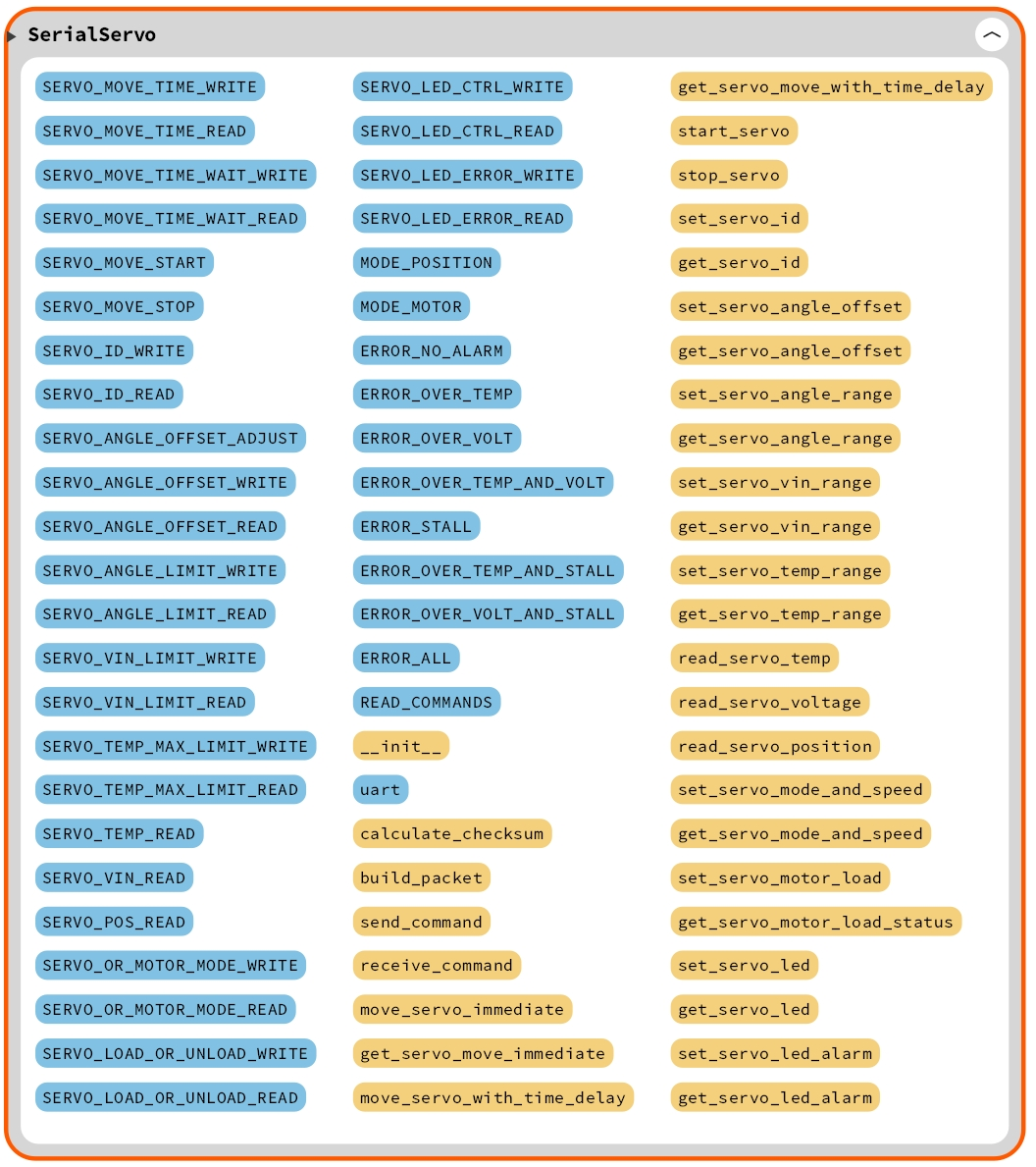
This class encapsulates all functions related to servo control, including generating and sending control commands, receiving servo feedback, and reading servo status.
Here, we first define the length of instructions and their parameters or the length of returned data as class constants:
# 串口舵机自定义类
class SerialServo:
    """
    串口舵机控制类,用于生成和发送控制指令。

    该类通过UART串口与舵机进行通信,支持构建控制指令包、计算校验和以及发送指令。
    支持可调的波特率和不同舵机的控制。

    Attributes:
        uart (machine.UART): 用于与舵机通信的UART实例。

    Class Variables:
        - 指令及其参数长度或返回数据长度的定义。
        - 各种舵机控制指令的定义,包括写入命令和读取命令。
        - 舵机工作模式的定义。
        - LED报警故障类型的定义。

    Methods:
        calculate_checksum(data: list[int]) -> int:
            计算校验和,确保数据的完整性和正确性。
        build_packet(servo_id: int, cmd: int, params: list[int]) -> bytearray:
            构建舵机指令包。
        send_command(servo_id: int, cmd: int, params: list[int] = []) -> None:
            发送控制指令到舵机。
        receive_command(expected_cmd: int, expected_data_len: int) -> list:
            接收并处理舵机返回的指令数据包。
        move_servo_immediate(servo_id: int, angle: float, time_ms: int) -> None:
            立即控制舵机转动到指定角度。
        get_servo_move_immediate(servo_id: int) -> tuple:
            获取舵机的预设角度和时间。
        move_servo_with_time_delay(servo_id: int, angle: float, time_ms: int) -> None:
            控制舵机延迟转动到指定角度。
        get_servo_move_with_time_delay(servo_id: int) -> tuple:
            获取舵机的预设角度和时间(延迟转动)。
        start_servo(servo_id: int) -> None:
            启动舵机的转动。
        stop_servo(servo_id: int) -> None:
            立即停止舵机转动并停在当前角度位置。
        set_servo_id(servo_id: int, new_id: int) -> None:
            设置舵机的新ID值。
        get_servo_id(servo_id: int) -> int:
            获取舵机的ID。
        set_servo_angle_offset(servo_id: int, angle: float, save_to_memory: bool = False) -> None:
            根据角度值调整舵机的偏差。
        get_servo_angle_offset(servo_id: int) -> float:
            获取舵机的偏差角度。
        set_servo_angle_range(servo_id: int, min_angle: float, max_angle: float) -> None:
            设置舵机的最小和最大角度限制。
        get_servo_angle_range(servo_id: int) -> tuple:
            获取舵机的角度限位。
        set_servo_vin_range(servo_id: int, min_vin: float, max_vin: float) -> None:
            设置舵机的最小和最大输入电压限制。
        get_servo_vin_range(servo_id: int) -> tuple:
            获取舵机的电压限制值。
        set_servo_temp_range(servo_id: int, max_temp: int) -> None:
            设置舵机的最高温度限制。
        get_servo_temp_range(servo_id: int) -> int:
            获取舵机的内部最高温度限制值。
        read_servo_temp(servo_id: int) -> int:
            获取舵机的实时温度。
        read_servo_voltage(servo_id: int) -> float:
            获取舵机的实时输入电压。
        read_serv:pos_read(servo_id: int) -> float:
            获取舵机的实时角度位置。
        set_servo_mode_and_speed(servo_id: int, mode: int, speed: int) -> None:
            设置舵机的工作模式和电机转速。
        get_servo_mode_and_speed(servo_id: int) -> tuple:
            获取舵机的工作模式和转动速度。
        set_servo_motor_load(servo_id: int, unload: bool) -> None:
            设置舵机的电机是否卸载掉电。
        get_servo_motor_load_status(servo_id: int) -> bool:
            获取舵机电机是否装载或卸载。
        set_servo_led(servo_id: int, led_on: bool) -> None:
            设置舵机的LED灯的亮灭状态。
        get_servo_led(servo_id: int) -> bool:
            获取舵机LED的亮灭状态。
        set_servo_led_alarm(servo_id: int, alarm_code: int) -> None:
            设置舵机LED闪烁报警对应的故障值。
        get_servo_led_alarm(servo_id: int) -> int:
            获取舵机LED故障报警状态。

    =================================================

        SerialServo Class:
    A class to control the serial servo, used to generate and send control commands.

    This class communicates with the servo through UART serial, supporting the construction of control command packets,
    checksum calculation, and command sending.
    It supports adjustable baud rates and control for various servo models.

    Attributes:
        uart (machine.UART): UART instance for communication with the servo.

    Class Variables:
        - Definitions of command lengths or return data lengths.
        - Definitions of various servo control commands, including write and read commands.
        - Definitions of servo working modes.
        - Definitions of LED alarm fault types.

    Methods:
        calculate_checksum(data: list[int]) -> int:
            Calculate checksum to ensure data integrity and correctness.
        build_packet(servo_id: int, cmd: int, params: list[int]) -> bytearray:
            Construct servo control command packet.
        send_command(servo_id: int, cmd: int, params: list[int] = []) -> None:
            Send control command to the servo.
        receive_command(expected_cmd: int, expected_data_len: int) -> list:
            Receive and process the response from the servo.
        move_servo_immediate(servo_id: int, angle: float, time_ms: int) -> None:
            Control the servo to move immediately to a specified angle.
        get_servo_move_immediate(servo_id: int) -> tuple:
            Get the servo's preset angle and time for immediate movement.
        move_servo_with_time_delay(servo_id: int, angle: float, time_ms: int) -> None:
            Control the servo to move to a specified angle with a delay.
        get_servo_move_with_time_delay(servo_id: int) -> tuple:
            Get the servo's preset angle and time for delayed movement.
        start_servo(servo_id: int) -> None:
            Start the servo's movement.
        stop_servo(servo_id: int) -> None:
            Immediately stop the servo and hold at the current position.
        set_servo_id(servo_id: int, new_id: int) -> None:
            Set a new ID for the servo.
        get_servo_id(servo_id: int) -> int:
            Get the current ID of the servo.
        set_servo_angle_offset(servo_id: int, angle: float, save_to_memory: bool = False) -> None:
            Adjust the servo's angle offset based on a specified angle.
        get_servo_angle_offset(servo_id: int) -> float:
            Get the current angle offset of the servo.
        set_servo_angle_range(servo_id: int, min_angle: float, max_angle: float) -> None:
            Set the minimum and maximum angle limits for the servo.
        get_servo_angle_range(servo_id: int) -> tuple:
            Get the current angle limits of the servo.
        set_servo_vin_range(servo_id: int, min_vin: float, max_vin: float) -> None:
            Set the minimum and maximum input voltage range for the servo.
        get_servo_vin_range(servo_id: int) -> tuple:
            Get the current input voltage range of the servo.
        set_servo_temp_range(servo_id: int, max_temp: int) -> None:
            Set the maximum temperature limit for the servo.
        get_servo_temp_range(servo_id: int) -> int:
            Get the current maximum temperature limit for the servo.
        read_servo_temp(servo_id: int) -> int:
            Read the current temperature of the servo.
        read_servo_voltage(servo_id: int) -> float:
            Read the current input voltage of the servo.
        read_servo_pos(servo_id: int) -> float:
            Read the current angle position of the servo.
        set_servo_mode_and_speed(servo_id: int, mode: int, speed: int) -> None:
            Set the working mode and motor speed for the servo.
        get_servo_mode_and_speed(servo_id: int) -> tuple:
            Get the current working mode and motor speed of the servo.
        set_servo_motor_load(servo_id: int, unload: bool) -> None:
            Set whether the servo motor is loaded or unloaded.
        get_servo_motor_load_status(servo_id: int) -> bool:
            Get the current load status of the servo motor.
        set_servo_led(servo_id: int, led_on: bool) -> None:
            Set the LED light status (on/off) of the servo.
        get_servo_led(servo_id: int) -> bool:
            Get the current LED light status of the servo.
        set_servo_led_alarm(servo_id: int, alarm_code: int) -> None:
            Set the LED alarm fault code for the servo.
        get_servo_led_alarm(servo_id: int) -> int:
            Get the current LED alarm fault code of the servo.

    """

    # 类变量:指令及其参数长度或返回数据长度
    # 写入指令及其对应的参数长度
    # 读取指令及其对应的参数长度和返回数据长度

    # 舵机立即转动写入命令
    SERVO_MOVE_TIME_WRITE = (1, 7)
    # 舵机立即转动参数读取命令
    SERVO_MOVE_TIME_READ = (2, 3, 7)

    # 舵机延迟转动写入命令
    SERVO_MOVE_TIME_WAIT_WRITE = (7, 7)
    # 舵机延迟转动读取命令
    SERVO_MOVE_TIME_WAIT_READ = (8, 3, 7)

    # 舵机开启转动指令(配合SERVO_MOVE_TIME_WAIT_WRITE指令使用)
    SERVO_MOVE_START = (11, 3)
    # 舵机停止转动指令
    SERVO_MOVE_STOP = (12, 3)

    # 舵机ID写入命令(支持掉电保存)
    SERVO_ID_WRITE = (13, 4)
    # 舵机ID读取命令
    SERVO_ID_READ = (14, 3, 4)

    # 舵机偏差调节指令(不支持掉电保存)
    SERVO_ANGLE_OFFSET_ADJUST = (17, 4)
    # 舵机偏差调节指令(支持掉电保存)
    SERVO_ANGLE_OFFSET_WRITE = (18, 3)
    # 舵机偏差调节读取指令
    SERVO_ANGLE_OFFSET_READ = (19, 3, 4)

    # 舵机角度限位写入命令(支持掉电保存)
    SERVO_ANGLE_LIMIT_WRITE = (20, 7)
    # 舵机角度限位读取命令
    SERVO_ANGLE_LIMIT_READ = (21, 3, 7)

    # 舵机电压限制写入命令(支持掉电保存)
    SERVO_VIN_LIMIT_WRITE = (22, 7)
    # 舵机电压限制读取命令
    SERVO_VIN_LIMIT_READ = (23, 3, 7)

    # 舵机温度限制写入命令(支持掉电保存)
    SERVO_TEMP_MAX_LIMIT_WRITE = (24, 4)
    # 舵机温度限制读取命令
    SERVO_TEMP_MAX_LIMIT_READ = (25, 3, 4)

    # 舵机实时温度读取指令
    SERVO_TEMP_READ = (26, 3, 4)
    # 舵机实时电压读取指令
    SERVO_VIN_READ = (27, 3, 5)
    # 舵机当前角度读取指令
    SERVO_POS_READ = (28, 3, 5)

    # 舵机模式切换指令(不支持掉电保存)
    SERVO_OR_MOTOR_MODE_WRITE = (29, 7)
    # 舵机模式及参数读取指令
    SERVO_OR_MOTOR_MODE_READ = (30, 3, 7)

    # 舵机上电/掉电控制指令(不支持掉电保存)
    SERVO_LOAD_OR_UNLOAD_WRITE = (31, 4)
    # 舵机上电/掉电读取指令
    SERVO_LOAD_OR_UNLOAD_READ = (32, 3, 4)

    # 舵机LED控制指令(支持掉电保存)
    SERVO_LED_CTRL_WRITE = (33, 4)
    # 舵机LED读取指令
    SERVO_LED_CTRL_READ = (34, 3, 4)

    # 舵机LED报警闪烁指令
    SERVO_LED_ERROR_WRITE = (35, 4)
    # 舵机LED报警闪烁值读取指令
    SERVO_LED_ERROR_READ = (36, 3, 4)

    # 类变量:舵机工作模式
    # 0 代表位置控制模式
    MODE_POSITION = 0
    # 1 代表电机控制模式
    MODE_MOTOR = 1

    # 类变量:LED报警故障类型
    ERROR_NO_ALARM = 0              # 无报警
    ERROR_OVER_TEMP = 1             # 过温报警
    ERROR_OVER_VOLT = 2             # 过压报警
    ERROR_OVER_TEMP_AND_VOLT = 3    # 过温和过压报警
    ERROR_STALL = 4                 # 堵转报警
    ERROR_OVER_TEMP_AND_STALL = 5   # 过温和堵转报警
    ERROR_OVER_VOLT_AND_STALL = 6   # 过压和堵转报警
    ERROR_ALL = 7                   # 过温、过压和堵转报警

    # 读取命令集合:根据指令的元组长度来确定哪些是读取命令(命令编号,参数长度,返回数据长度)
    READ_COMMANDS = {
        2,  # SERVO_MOVE_TIME_READ
        8,  # SERVO_MOVE_TIME_WAIT_READ
        14, # SERVO_ID_READ
        19, # SERVO_ANGLE_OFFSET_READ
        21, # SERVO_ANGLE_LIMIT_READ
        23, # SERVO_VIN_LIMIT_READ
        25, # SERVO_TEMP_MAX_LIMIT_READ
        26, # SERVO_TEMP_READ
        27, # SERVO_VIN_READ
        28, # SERVO_POS_READ
        30, # SERVO_OR_MOTOR_MODE_READ
        32, # SERVO_LOAD_OR_UNLOAD_READ
        34, # SERVO_LED_CTRL_READ
        36  # SERVO_LED_ERROR_READ
    }
For example:
SERVO_MOVE_TIME_WRITE and SERVO_MOVE_TIME_READ are commands and their parameter formats related to servo position control.
SERVO_ID_WRITE and SERVO_ID_READ are read and write commands related to the servo ID.
These constant helper classes ensure that the correct instructions are sent and the returned data is parsed correctly when communicating.
READ_COMMANDS The set defines the numbers of all read commands that correspond to data read requests from the servo, such as real-time voltage, angle, temperature, etc. This set is convenient for determining whether the received data is the expected read command in the receive_command () method.
In the initialization method, we only need to bind the externally initialized UART instance:
    def __init__(self, uart: UART) -> None:
        """
        初始化串口舵机控制类。

        Args:
            uart (UART): 使用的UART实例。

        ===================================================

        Initialize the Serial Servo Control Class.

        Args:
            uart (UART): The UART instance used for communication with the servo.

        """
        self.uart = uart
The core methods of the serial servo class are as follows:
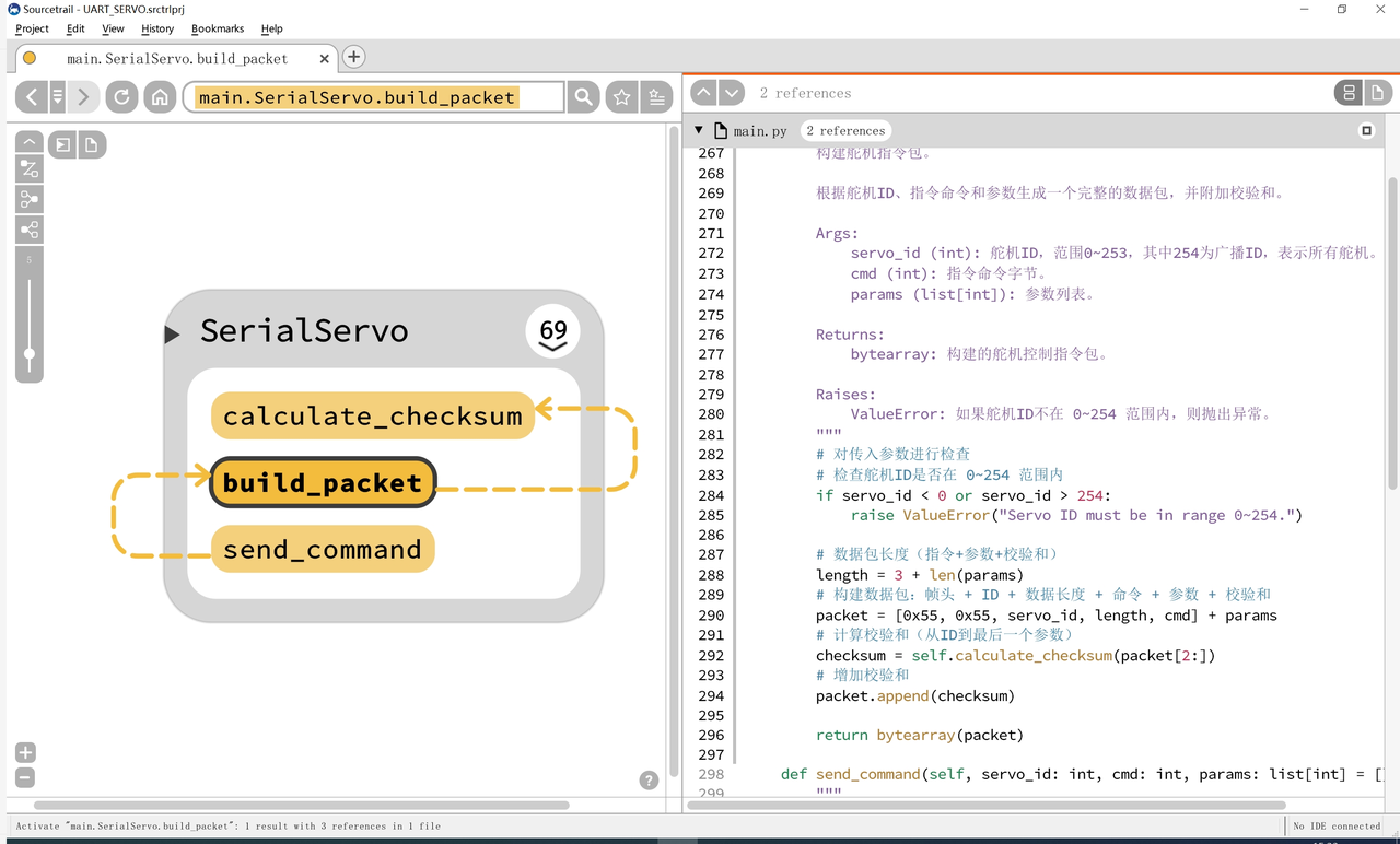
Packet Construction Methodbuild_packet:
This method is used to construct the command packet for servo control, which consists of the following parts:
Frame Header: Fixed as 0x55,0x55
Servo ID: a unique identifier for each servo
Data Length: including instructions and parameters
Instruction No.: Specific control instruction
Parameter: the parameter of a control instruction
Checksum: Used to verify the integrity of data packets
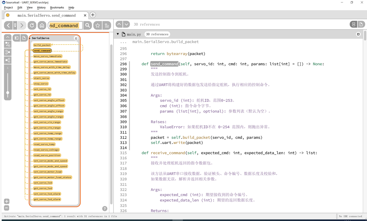
Command sending methodsend_command: This method constructs a command packet and sends it to the servo via UART. It calls build_packet () to construct the data packet, and sends the data via self. uart. write ():
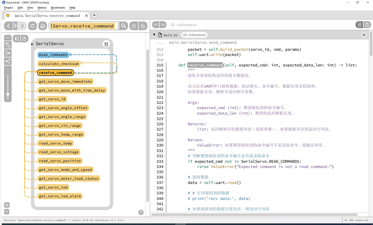
Instruction Receiving Methodreceive_command : receive_command () is a method used to receive feedback data from the servo motor, and the working process of this method is as follows:
Command Verification: Confirm that the received command is a read command rather than any other type of command.
Data Check: Verify whether the frame header of the data is correct, whether the command number matches, and whether the data length meets the expectation.
Checksum Verification: Verify whether the checksum of the received data packet is correct to ensure that the data has not been tampered with.
Data Parsing: Parse and return the status or data of the servo (such as voltage, angle, etc.) according to the length of the returned data.
If the data packet is invalid (e. g., checksum error, mismatched data length, etc.), this method will return an empty list.
SerialServo class all the upper layer function methods (such as steering gear rotation, parameter configuration, state reading, etc.) are based on build_packet (packaging), send_command (sending), receive_command (receiving and parsing) three core communication modules.These three core methods constitute the driven "communication pipeline", and the upper-layer methods are essentially the "business-oriented encapsulation" of this pipeline — which converts the "physical quantities"(such as angle and voltage) input by users into the "original parameters" required by the protocol, and then completes the interaction with the steering gear through the core module.
According to functional scenarios, upper-layer methods can be divided into "write operations that only send instructions" and "read-write operations that send first and then receive", and the two have different calling logics for the core module:
Write operation methods: only call send_command (including build_packet), operations that do not require the servo to return data (such as controlling rotation, setting ID, starting and stopping the servo, etc.), the core of which is "packaging and sending parameters".
Read-write operation methods: invoke send_command + receive_command; for operations that require acquiring the servo status (such as reading temperature, position, angle deviation, etc.), the core logic is "send the read command first, then receive and parse the response".
For example the move_servo_immediate method, which is a write operation type method, the code is as follows:
    def move_servo_immediate(self, servo_id: int, angle: float, time_ms: int) -> None:
        """
        立即控制舵机转动到指定角度。

        该方法使用 SERVO_MOVE_TIME_WRITE 指令,在给定时间内将舵机转动到指定的角度。

        Args:
            servo_id (int): 舵机ID,范围0~253。
            angle (float): 目标角度(0~240度范围内)。每个单位表示 0.24 度。
            time_ms (int): 转动时间(0~30000 毫秒),表示舵机转动到指定角度的时间。

        Raises:
            ValueError: 如果角度不在 0~240度范围内、舵机ID不在0~253或时间不在范围内,则抛出异常。

        ===================================================

        Immediately control the servo to rotate to the specified angle.

        Args:
            servo_id (int): Servo ID, range 0~253.
            angle (float): Target angle (0~240 degrees). Each unit represents 0.24 degrees.
            time_ms (int): Time to rotate (0~30000 milliseconds), indicating the time for the servo to rotate to the specified angle.

        Raises:
            ValueError: If the angle is not in the range 0~240, the servo ID is not in the range 0~253,
            or the time is not in the range, an exception will be raised.

        """
        # 判断角度是否在 0~240度范围内
        if angle < 0 or angle > 240:
            raise ValueError("Angle must be in range 0~240.")

        # 判断时间是否在 0~30000 毫秒范围内
        if time_ms < 0 or time_ms > 30000:
            raise ValueError("Time must be in range 0~30000.")

        # 将角度转换为舵机控制指令所需的低八位和高八位
        # 转换为整数并限制为低8位
        angle_low = int(angle / 0.24) & 0xFF
        # 获取高8位
        angle_high = (int(angle / 0.24) >> 8) & 0xFF

        # 将时间转换为低八位和高八位
        # 转换为低8位
        time_low = time_ms & 0xFF
        # 获取高8位
        time_high = (time_ms >> 8) & 0xFF

        # 发送 SERVO_MOVE_TIME_WRITE 指令
        self.send_command(servo_id, SerialServo.SERVO_MOVE_TIME_WRITE[0], [angle_low, angle_high, time_low, time_high])
It does not require operations that rely on servo return data (such as controlling rotation, setting ID, starting/stopping the servo, etc.), and its core logic is "packaging and sending parameters": when a user inputs the servo ID, target angle and rotation duration, the move_servo_immediate method first performs validity check, then converts the target angle and rotation duration into the lower 8 bits and upper 8 bits required for the servo control command, and finally calls the send_command method (which internally invokes build_packet) to transmit the data.
For read-write operation methods, the process is as follows:
Send read command (send_command)
delay waiting
Receive response (receive_command)
Parse Parameters
Physical Quantity Conversion
Return Result
Taking the read_servo_position method as an example, which belongs to the read-write operation type methods, the code is as follows:
    def read_servo_position(self, servo_id: int) -> float:
        """
        获取舵机的实时角度位置。

        该方法通过舵机ID发送 `SERVO_POS_READ` 指令来读取舵机的当前角度位置。
        返回的角度位置值需要根据范围 0~1000 映射到角度 0~240°。

        Args:
            servo_id (int): 舵机的ID。

        Returns:
            float: 返回舵机当前的角度位置值,单位为度,范围 0~240°。
                   如果读取失败,则返回 None。

        Raises:
            ValueError: 如果角度位置不在 0~240 度范围内,则抛出异常。

        =======================================================

        Get the real-time position of the servo.

        This method sends the `SERVO_POS_READ` command using the servo's ID to read the current angle position of the servo.
        The returned position value needs to be mapped from the range 0~1000 to the angle range 0~240°.

        Args:
            servo_id (int): The servo's ID.

        Returns:
            float: The current angle position of the servo, in degrees, with a range of 0~240°.
                   If the read operation fails, it returns None.

        Raises:
            ValueError: If the position is not within the range of 0~240°, an exception will be raised.

        """
        # 发送SERVO_POS_READ命令
        self.send_command(servo_id, SerialServo.SERVO_POS_READ[0], [])

        # 延迟5ms再接收数据
        time.sleep_ms(5)

        # 接收并解析返回的数据
        params = self.receive_command(SerialServo.SERVO_POS_READ[0], SerialServo.SERVO_POS_READ[2])

        # 如果没有接收到数据,则返回None
        if len(params) == 0:
            return None

        # 将角度位置的低高字节合并为一个16位整数
        position_value = params[0] + (params[1] << 8)

        # 将值转换为 signed short int 型数据(可能为负值)
        # 判断是否为负值
        if position_value >= 0x8000:
            # 如果是负值,进行补码转换
            position_value -= 0x10000

        # 将位置值转换为角度值,映射到 0~240° 范围
        position_angle = (position_value / 1000) * 240

        # 判断角度值是否在合理范围内
        if not (0 <= position_angle <= 240):
            raise ValueError("Position is out of range.")

        return position_angle
3.2 Experimental Preparations and Experimental Phenomena
Here, you can check it out on our blog:
The address is: https://www.cnblogs.com/FreakEmbedded/p/18742422 .