Basics: RGB LED Hardware Principles and Raspberry Pi Pico PWM Control Practice
MicroPython PWM‑based RGB‑LED driver class, supporting RGB‑value mapping and named‑color switching for multi‑color lighting effects.
COMPONENTS
PROJECT DESCRIPTION
【Preliminary Note】The original hardware example in this article was written based on the RP2040. The actual hardware used in this hands-on demonstration features the W55RP20 as the main controller chip. The circuit logic and UF2 flashing operation principles are universally applicable, with only the main controller model differing. The original chip model mentioned in the circuit descriptions below is provided for reference purposes only.
PWM Signal Controls RGB LED
1. Basics of RGB LEDs
An RGB LED (Red, Green, Blue Light-Emitting Diode) is a light-emitting device composed of a combination of three LEDs in red, green and blue colors; by adjusting the brightness of these three colors, it can generate light of various colors. RGB LEDs are widely used in scenarios such as display screens, decorative lighting and indicator lights.
An RGB LED typically integrates three independent LED chips, each responsible for emitting red, green or blue light respectively. These chips can be controlled independently, so a wide range of colors can be mixed by combining different brightness levels:
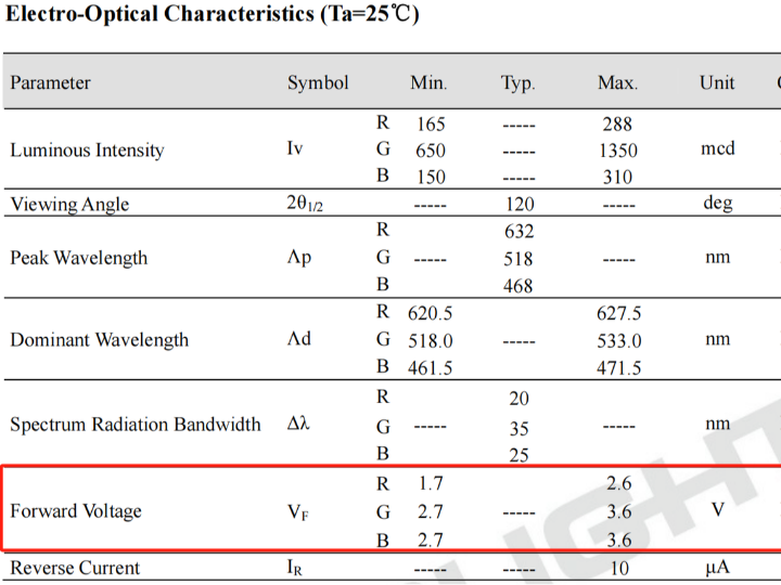
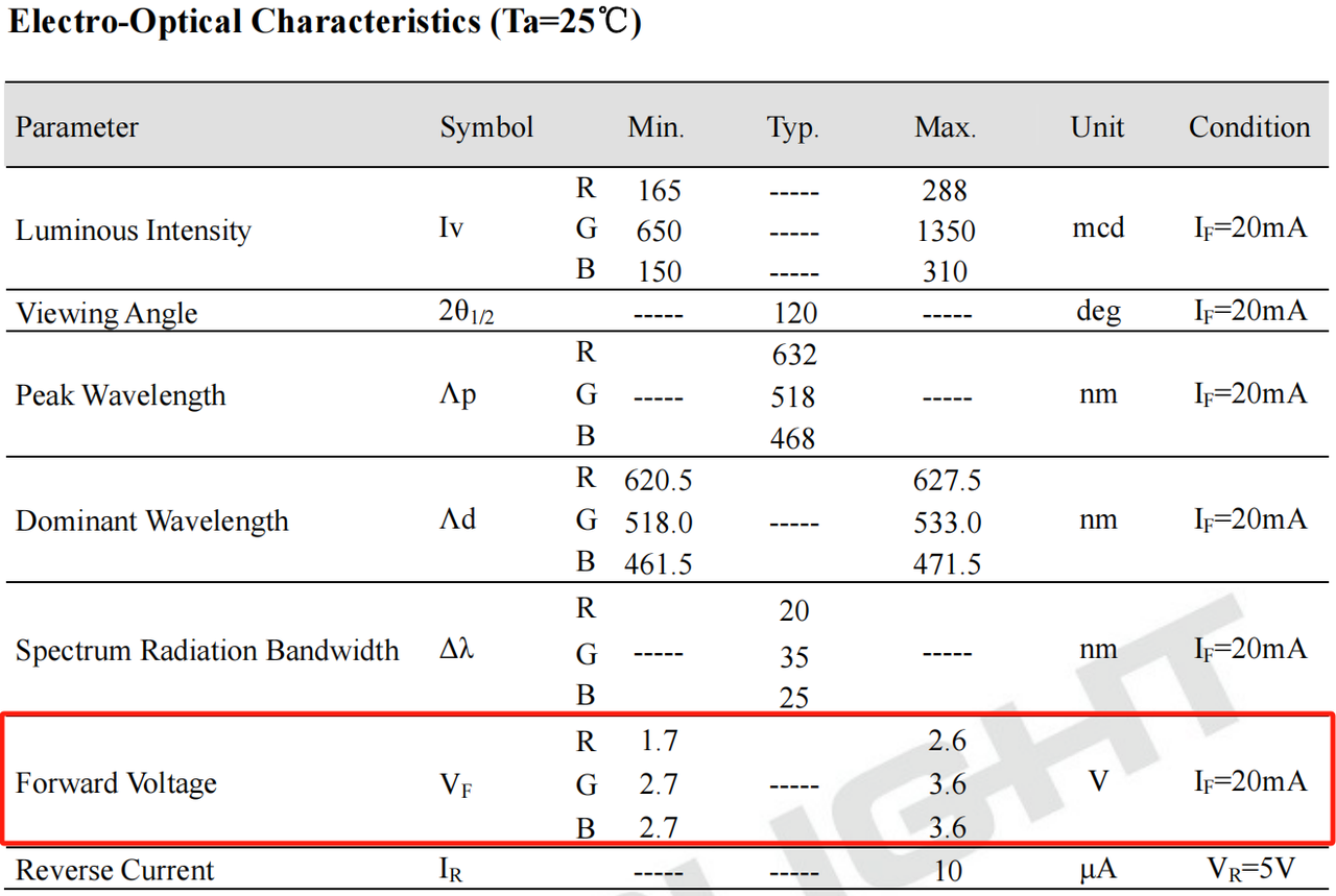
The electrical parameters of R6GHBHW RGB LED, where the VF forward voltage of each Light Emitting Diode is different
Red (R): Emits red light, and typically operates at a relatively low voltage
Green (G): Emits green light with a medium operating voltage
Blue (B): Emits blue light and typically operates at a relatively high voltage.
RGB LEDs can produce different colors by mixing red, green, and blue light. We can use Pulse Width Modulation (PWM) to precisely control the brightness of each LED, and the brightness of each color can be adjusted by changing the voltage duty cycle (0~100%), thus realizing rich color variations.
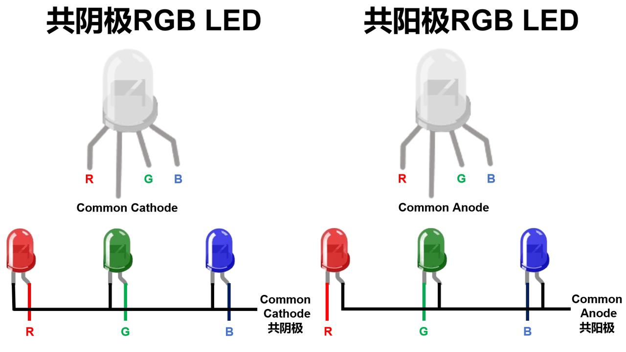
RGB LEDs can be divided into the following two types according to their structure:
Common cathode: The cathodes of all LEDs are connected together, and their anodes are respectively connected to different control terminals of the circuit
Common Anode: The anodes of all LEDs are connected together, while their cathodes are respectively connected to different control terminals of the circuit
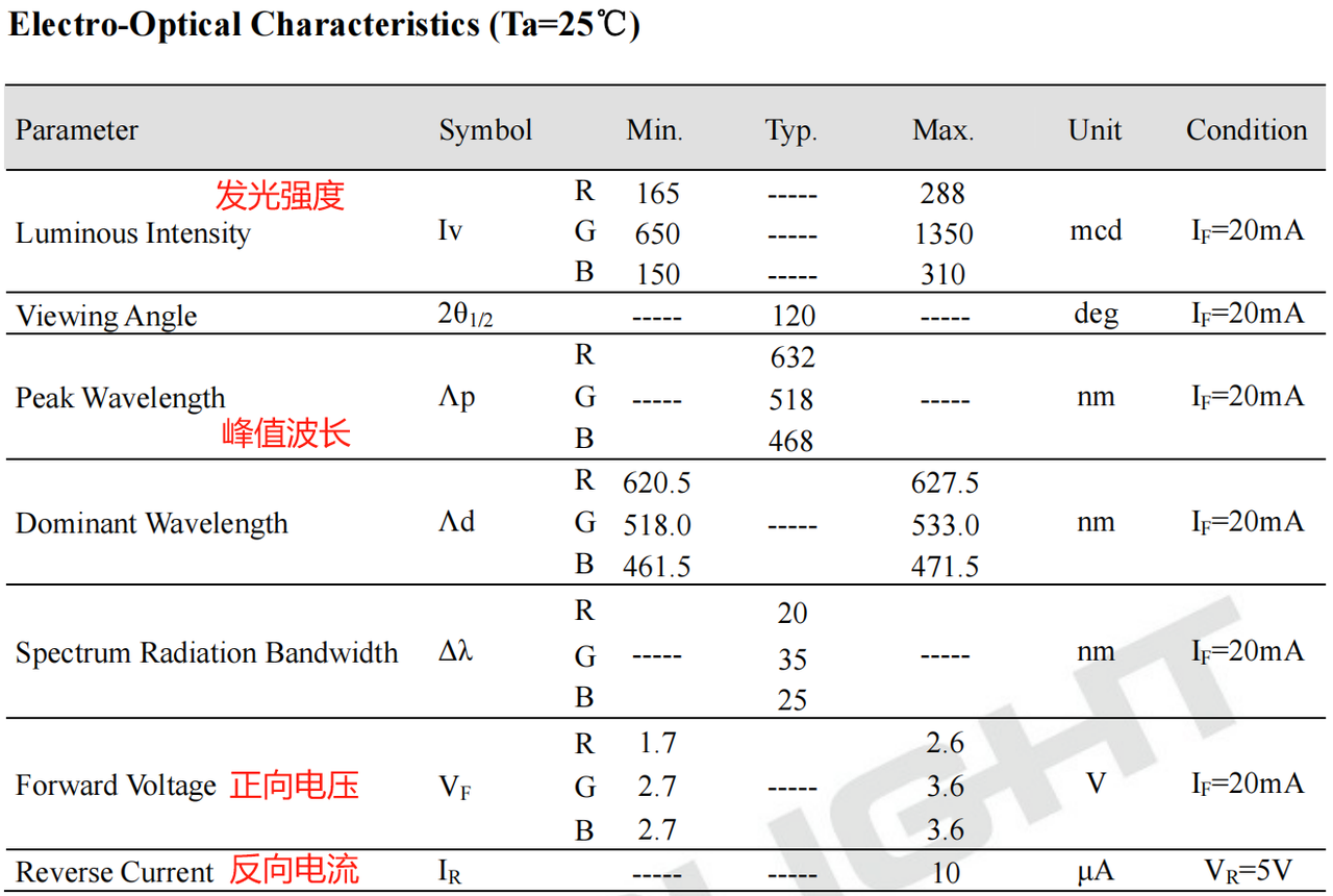
The parameters of an RGB LED reflect its electrical and optical properties, which not only determine the luminous efficacy, color and brightness of the LED but also affect its application in circuits:
Forward Voltage (VF): Forward voltage refers to the voltage difference between the two electrodes when an LED is forward conducting; LEDs of different colors have different operating voltage ranges due to variations in their constituent materials.
Maximum Forward Current (IF): Maximum forward current refers to the maximum current allowed to pass through an LED during normal operation, with a common value of 20mA; a current higher than this may damage the LED, cause overheating or reduce the service life of the LED
Luminous Intensity (Iv): Luminous intensity is usually expressed in millicandela (mcd), which describes the brightness of the light emitted by an LED. The luminous intensity depends on the magnitude of the current: the higher the current, the higher the luminous intensity of the LED.
Wavelength: The wavelength of an LED determines the color of the light it emits, and the wavelength range of an RGB LED represents its color; the difference in wavelength is determined by the material of the LED, and photons of different wavelengths have different energies, so LEDs of different colors require different operating voltages.
Reverse Current (IR): Reverse current refers to the current flowing through an LED when it is reverse-biased. Generally, the reverse current of an LED is extremely small, with a typical value on the order of microamps (e. g., 10μA); if the reverse current is excessively high, it may cause damage to the LED.
Taking the electrical parameters of the R6GHBHW-A01 RGB LED as an example, they are shown in the following figure:
Here, we need to add current-limiting resistors to the RGB LED diodes to ensure that the LEDs will not be damaged due to excessive current. The calculation formula for the current-limiting resistor is as follows:
$$R = \frac{V_{in} - V_F}{I_F} $$
The meanings of the respective parameters are as follows:
Vin: Power supply voltage, typically the power supply voltage for LED circuits
VF: Forward Voltage of an LED. The VF value varies for LEDs of different colors.
IF: Operating current of the LED, which is typically 20mA (i. e. 0.02A)
2. PWM Signal Control of RGB LED
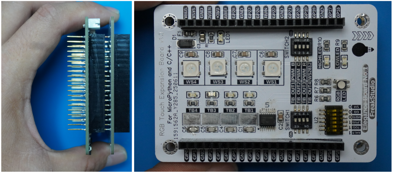
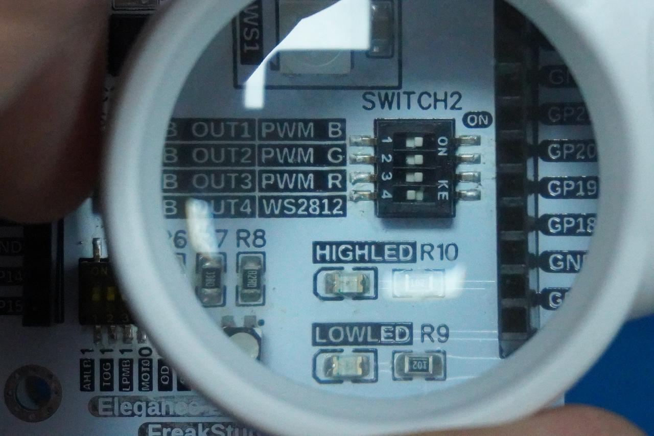
Here, we need to insert the Fengya No. 1 Board - Environment and Storage Acquisition Board into the Fengya No. 1 Board - Universal Compatible Expansion Board, and meanwhile turn on the PWM_B, PWM_G and PWM_R options of the SWITCH2 DIP switch on the Fengya No. 1 Board - Environment and Storage Acquisition Board. The physical connection diagram is shown as follows:
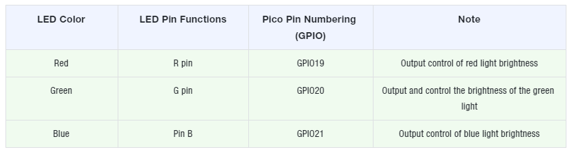
The pin connections are shown in the following table:
All the code for the following experiments is open-source and can be found in the material package we provide under the elegance-devkit v1\Demo\27 PWM_RGBLED folder.
In the following code, we use the PWM module to control the GPIO pins of the Raspberry Pi Pico to output PWM signals, thereby driving the RGB LED. The sample code is as follows:
Here, we first define a global dictionary that stores the RGB values of common colors, with each color corresponding to an RGB tuple; for example, red is (255,0, 0), and then we define a map_to_pwm function that maps RGB values (in the range of 0-255) to PWM values (in the range of 0-65535).
Next, we defined an RGB LED control class to encapsulate the control logic of the RGB LED. In the initialization method, we pass the numbers of the red, green and blue pins connected to the RGB LED, initialize these pins to the PWM output mode respectively, set the PWM frequency to 1000Hz, and define two methods:
set_color_by_name () method: Sets the color of the RGB LED by color name. It looks up the RGB value corresponding to the color name from the global dictionary COLOR_PWM_VALUES, and returns (0,0, 0) by default if no match is found, which means turning off the LED
set_color () method: Used to set the color of the RGB LED, which accepts three parameters (the duty cycles of red, green and blue, ranging from 0 to 255). It uses map_to_pwm () to map the RGB values to a 16-bit PWM duty cycle, and sets the PWM value of each color channel via the duty_u16 () method
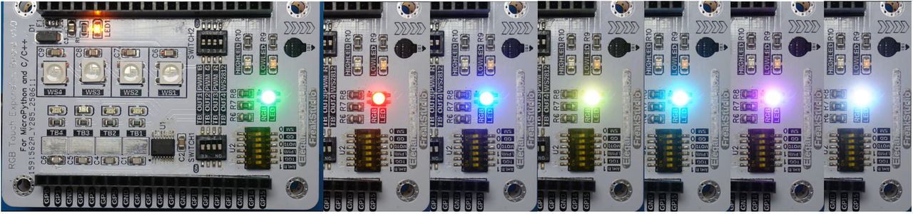
After flashing the code, you can see the on-board RGB LED cycle through and emit lights of different colors.