Advanced Stepper Motor Control for Raspberry Pi Pico: A Complete Guide to Non‑Blocking Implementatio
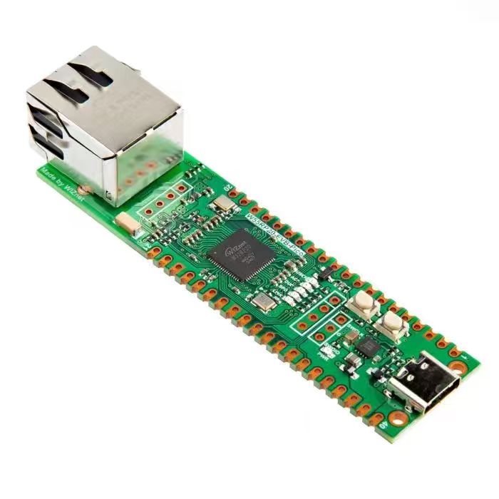
This tutorial presents PIO-based stepper motor control on the Feng No.1 board. Different from blocking GPIO software delay driving, the independent PIO
PROJECT DESCRIPTION
Here, we use PIO to implement single-phase drive control of a stepper motor. In short, single-phase drive control controls the energizing sequence and frequency of the stepper motor's 4 winding pairs, thereby achieving precise control of the motor's rotation angle and speed. For details, refer to the stepper motor introduction in Section 4 GPIO General Purpose Input/Output; we will not repeat it here.
As you can see, when driving a stepper motor with GPIO before, it was usually necessary to control the pin states in the main program through loops and delays. This approach blocks the main program, preventing the CPU from handling other tasks at the same time. PIO, in contrast, is an independent hardware peripheral that can run in parallel, so the main program can continue executing other tasks (such as processing sensor data, communication, etc.) while the PIO precisely controls the stepper motor.
Moreover, GPIO timing control relies on software delays (such as time.sleep_ms()), whose accuracy is limited by the operating system's scheduling and CPU load. PIO, however, can run at a fixed clock frequency, providing more precise timing control.
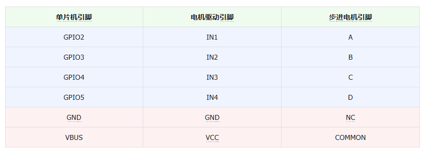
Here, we use the long-pin headers on the Fengya One Board - Universal Compatible Expansion Board to connect to the logic input interface on the Fengya One Board - Stepper Motor Driver Board. The pins used are shown in the following table:
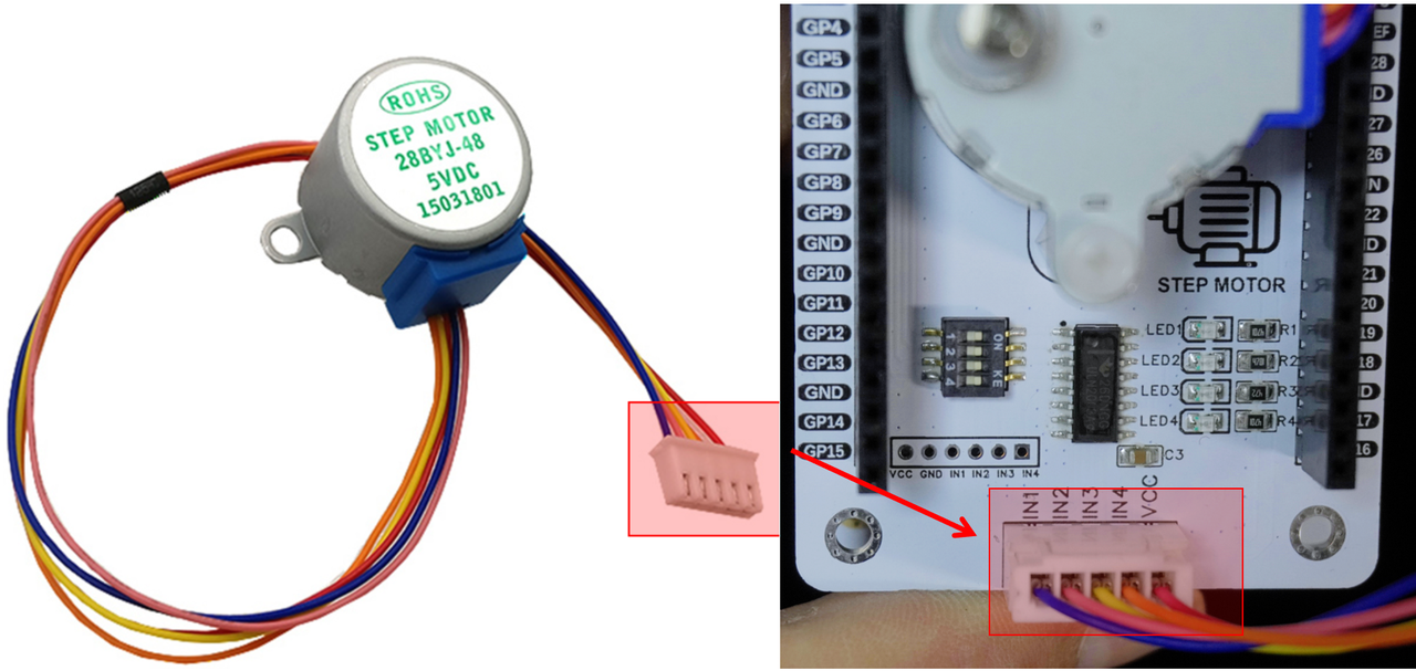
Then connect the logic output interface on the stepper motor driver board to the stepper motor:
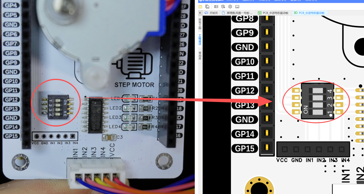
At the same time, turn on the DIP switches on the Fengya One Board - Stepper Motor Driver Board:
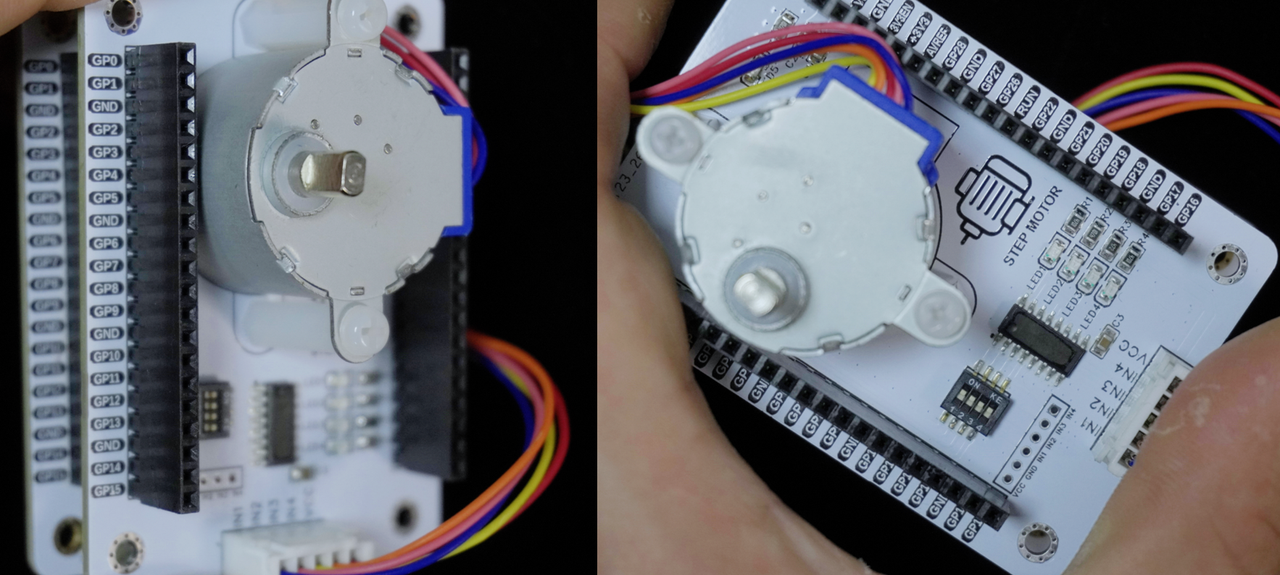
The overall connection is shown in the following figure:
The following code can be found in the elegance-devkit v1\Demo\34 PIO_StepMotor folder in our resource package.
The sample code is as follows:
from machine import Pin
import rp2
import time
@rp2.asm_pio(set_init=(rp2.PIO.OUT_LOW, rp2.PIO.OUT_LOW,
rp2.PIO.OUT_LOW, rp2.PIO.OUT_LOW))
def step_motor() -> None:
"""
Define the PIO program for stepper motor control.
Args:
None
Returns:
None
Description:
This PIO program controls the rotation of the stepper motor by setting the states of the 4 GPIO pins.
Each pin is set to high level in turn while the other pins are set to low level, forming the single-phase control sequence of the stepper motor.
"""
wrap_target()
set(pins, 0b0001) [7]
set(pins, 0b0010) [7]
set(pins, 0b0100) [7]
set(pins, 0b1000) [7]
wrap()
time.sleep(3)
print("FreakStudio: Using PIO to control step motor")
sm = rp2.StateMachine(0, step_motor, freq=2000, set_base=Pin(2))
sm.active(1)
while True:
passHere, in the PIO program, we use the set instruction to write 4-bit binary data to control the energizing of the stepper motor's 4 winding pairs (setting a pin to high level energizes 1 winding pair):
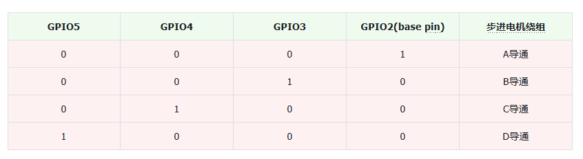
We can also use the set instruction to write decimal 1, 2, 4, 8 or hexadecimal 0x1, 0x2, ..., with the same effect.
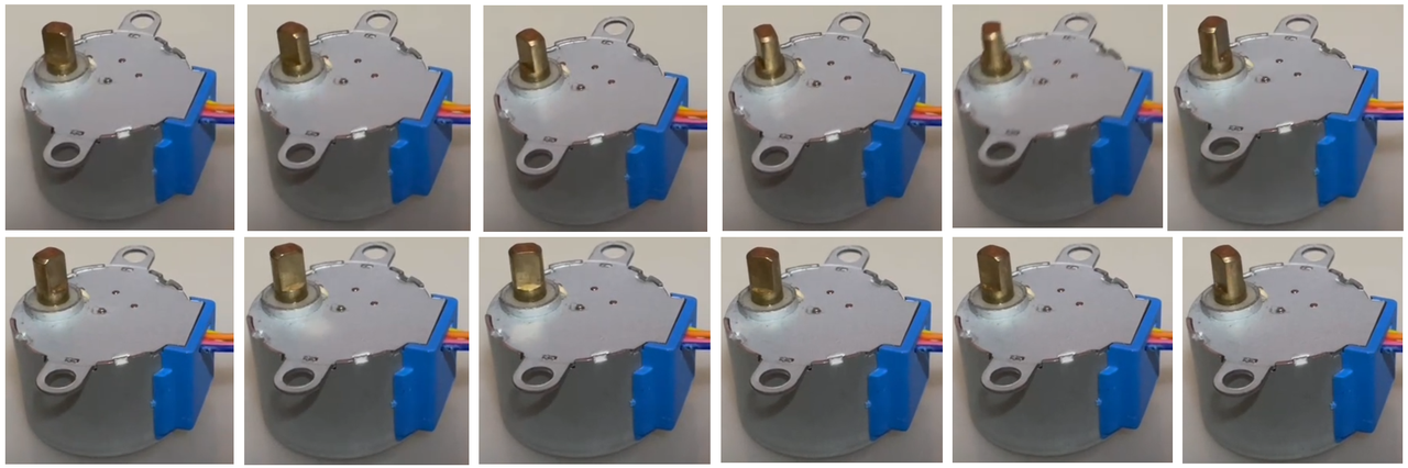
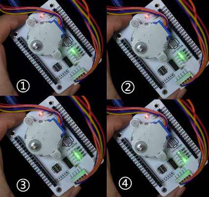
After flashing the code, you can see the stepper motor rotating. Through the use of the PIO peripheral, we have achieved non-blocking driving of the stepper motor: