



A Comprehensive Guide to the USB Protocol: An Overview of the Universal Serial Bus, From History and
This paper introduces USB standard, its birth background, version speed differences, tiered star topology, hub cascading, Type-A/B/C connectors, differential wi
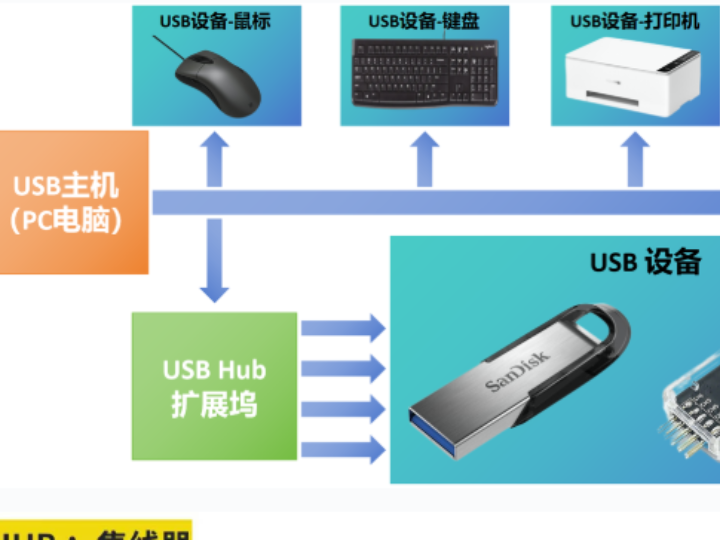
USB (Universal Serial Bus) is a widely used universal serial bus standard that provides a standard data transfer interface between computer devices and peripheral devices. It is a plug-and-play bus standard that allows users to connect and use various peripheral devices on a computer, such as mice, keyboards, printers, scanners, etc.
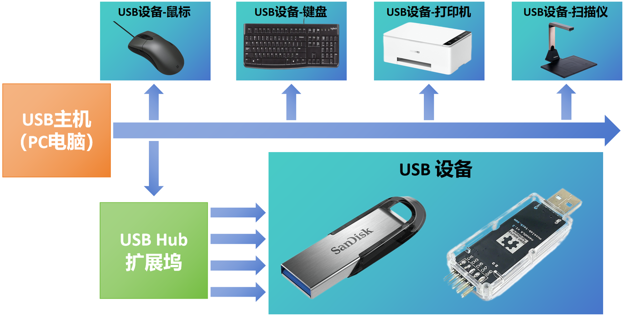
USB connections use a master-slave architecture; the host device controls and manages the entire USB system.
So far, the USB protocol has a total of four versions:
USB 1.0/1.1: supports a maximum data transfer speed of 12Mbps
USB 2.0: supports a maximum data transfer speed of 480Mbps
USB 3.x: includes USB 3.0, 3.1, and 3.2, and supports a maximum data transfer speed of 10Gbps
USB4: supports a maximum data transfer speed of 40Gbps and is compatible with the Thunderbolt 3 protocol
There are three types of electrical connection interfaces that we most commonly see using the USB protocol in daily life:
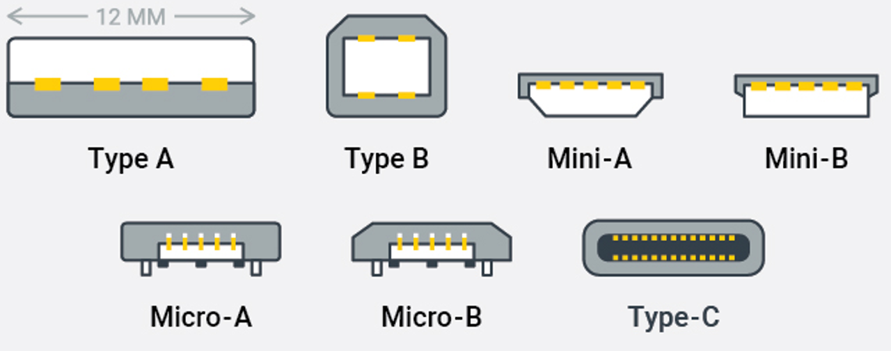
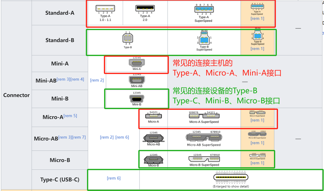
USB Type-A: the most common standard USB interface, used for host devices
USB Type-B: used for peripheral devices, such as printers, scanners, etc.
USB Type-C: adopts a symmetrical design, can be plugged in on either side, and provides higher power delivery capability
2. History of the USB Protocol
On early PCs, there were serial ports and parallel ports, and even mice, keyboards, and game controllers had specific interfaces. Moreover, none of these interfaces supported hot-plugging; devices could only work properly if they were plugged in before the PC was powered on. In addition, these different interfaces also consumed precious CPU resources (such as hardware interrupts and DMA channels).
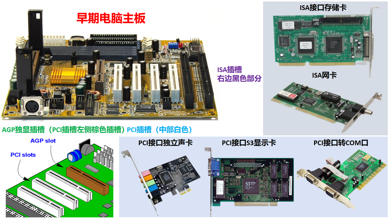
For computers in the early 1990s, apart from the serial COM port, PS2 keyboard/mouse interface, and RS232 interface (at that time, only high-end computer motherboards came with these three interfaces), most other modules needed to be connected through PCI, AGP, and ISA parallel interfaces, such as the common graphics cards, sound cards, network cards, video decoder cards, and LPT printer interfaces. In fact, many low-end computers had weak CPU floating-point performance, so if a graphical interface was desired, an external "coprocessor" was needed (such as an 80386 paired with an 80387 coprocessor).
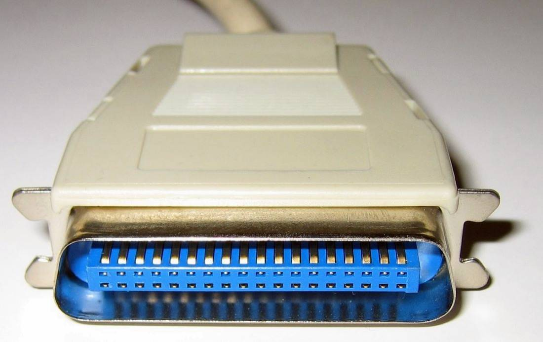 Before USB came out, data transfer mainly used parallel ports.
To solve these problems, Ajay Bhatt proposed the concept of the universal serial bus, i.e., USB. One of USB's core design concepts is to provide a unified solution for the various interfaces on a PC while replacing the many different interfaces and slots on the computer motherboard.
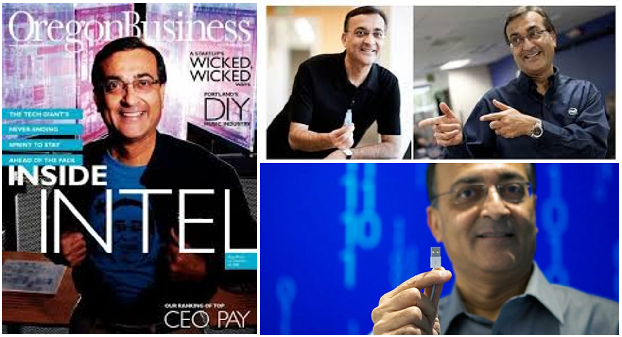
Ajay Bhatt and his team worked with six companies, including Intel, IBM, Microsoft, DEC, NEC, Compaq, and Nortel, on joint development. Finally, in 1995, the first USB-supporting integrated circuit was produced by Intel, and in November 1995, the first commercially usable USB 1.0 RRC standard was released. At the same time, the seven companies jointly founded the non-profit organization USB-IF (USB Implementers Forum). Before this, USB 0.8, USB 0.9, and USB 0.99 were released that year as "pre-release" versions, but they were not yet used commercially.
USB 1.0 provides two communication rate modes:
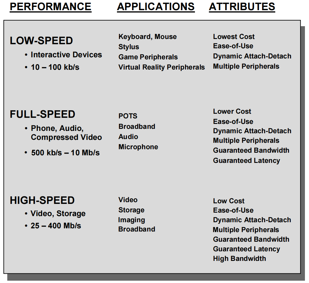
Low Speed version: communication rate of 1.5 Mb/s
Full Speed version: communication rate of 12 Mb/s
USB 1.0 supports adaptive configuration and can automatically adapt to peripheral devices without the user changing device settings. The interface also supports hot-plugging, so devices can be replaced without restarting the host. Although it was the first commercial version of USB, it was not widely accepted by the market, and very few devices were available to consumers.
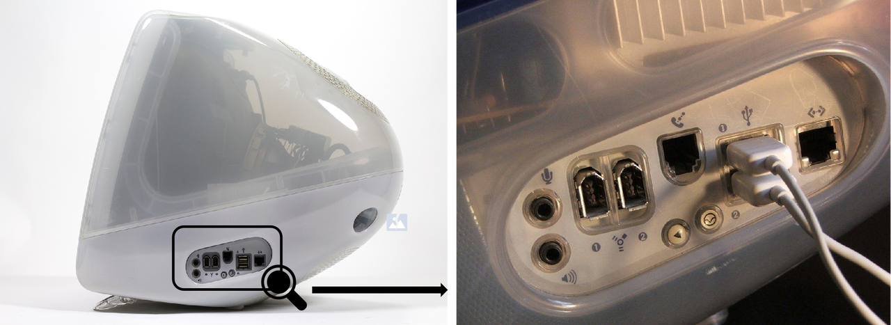
Interestingly, although Intel was the first company to invest in USB technology, the world's first product adopting USB technology was not developed by Intel (but the world's first USB-supporting integrated circuit was produced by Intel; note the difference!). The world's first product adopting USB technology was Apple's iMac G3 released in 1998, which used the USB 1.1 standard established in 1998.
As the market demanded increasing compatibility between PCs and their various peripheral devices, and applications became more complex, the requirements for data transfer rates also gradually increased. USB 2.0 was released in April 2000. In addition to being compatible with USB 1.x full-speed signaling, it added an operating mode supporting a higher maximum signaling rate of 480 Mbit/s, called High Speed mode. USB 2.0 also provides plug-and-play functionality for multimedia and storage devices, and supports powering via USB connectors up to 5 V and 500 mA.
To meet the growing demand for communication rates, in 2008 USB-IF introduced the USB 3.0 standard, which can reach a rate of 5Gbit/s, called SuperSpeed mode. Later, there are also SuperSpeed+ mode and SuperSpeed++ mode, which can theoretically reach rates of 10Gbit/s and 20Gbit/s.
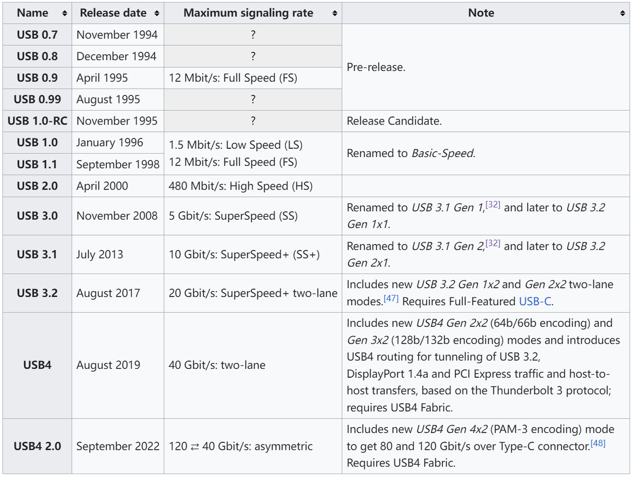
The communication rates and feature changes of each USB version can be seen in the following table:
3. USB System Overview
The USB system is a master-slave communication system with a "tiered star topology" structure. It consists of one host and up to 127 peripherals (Devices or Peripheral).
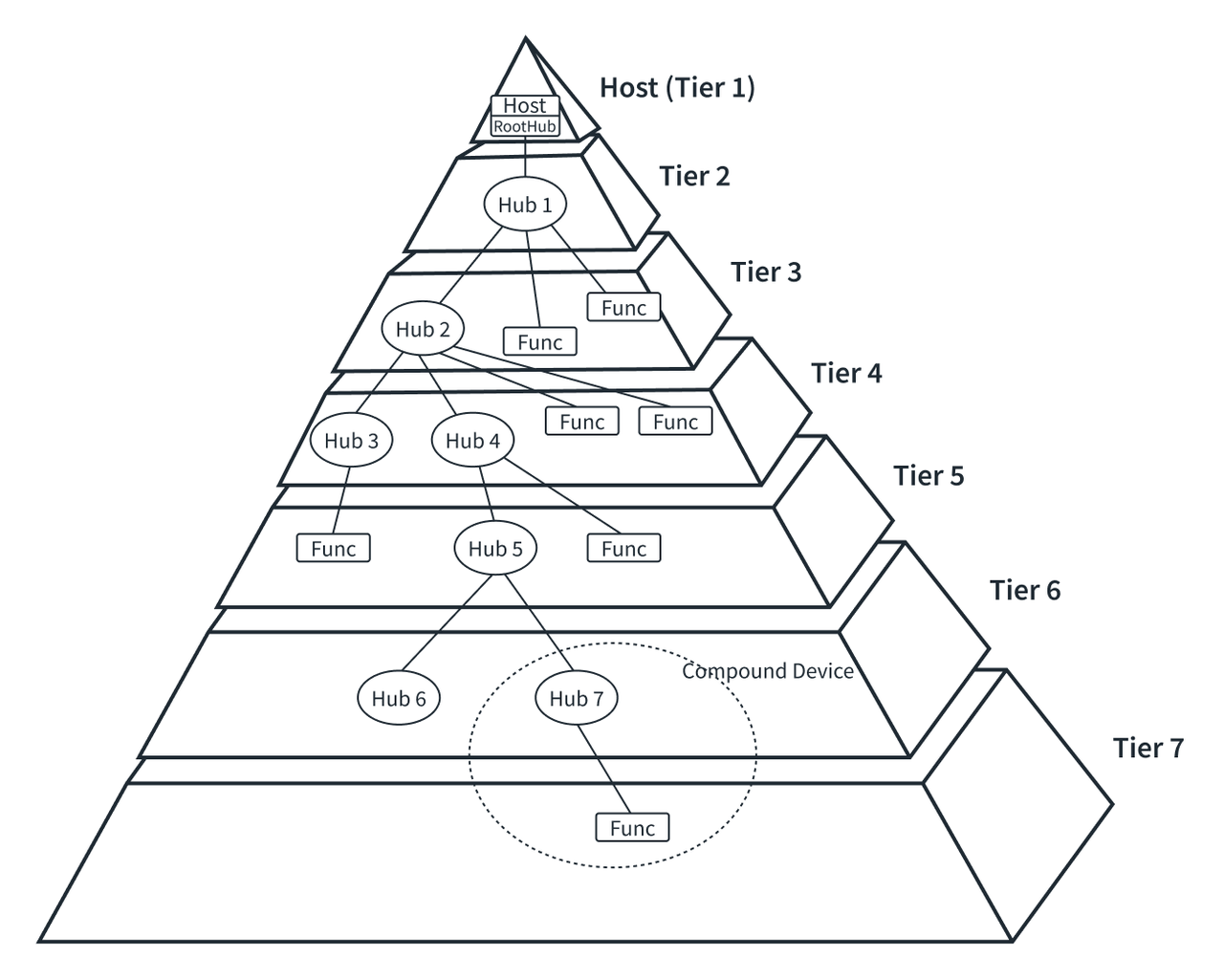
Peripherals come in two types: function devices (Functions) and hubs (HUB):
Function devices (Functions): devices that cannot host other USB devices; common devices like mice and keyboards are function devices
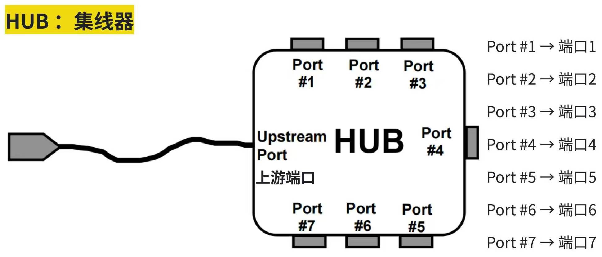
Hubs (HUB): peripherals that provide USB interface expansion capability, which can host function devices or hubs
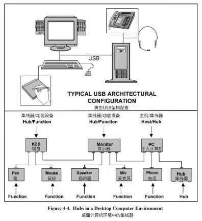
Through hub cascading (mounting hubs on hubs), more peripherals can be mounted, eventually forming a pyramid structure like the left figure. At the top of the pyramid are the host and root hub, which can connect function devices or hubs, layer by layer downward, forming a tiered star connection topology, the so-called "Tierd star topology". The protocol specifies a maximum of 7 network layers, i.e., 5 cascaded hubs.
USB uses a polling broadcast mechanism to transmit data. All transmissions are initiated by the host, and only one data packet is allowed to transmit at a time. Devices are distinguished by a 7-bit bus address, where address 0 is reserved and cannot be used by users; it is used for devices that have not been assigned an address. Therefore, one host supports at most 127 devices.
After a peripheral is connected to the bus, it must first undergo an enumeration operation before it can be used. The enumeration operation is, on one hand, to assign the address mentioned above; on the other hand, it obtains the device descriptors to determine information such as the device type and manufacturer, so that the host can select the corresponding driver. In the USB protocol, function devices are further subdivided according to different functions, such as HID, CDC, etc., which we will describe in detail in the subsequent introduction.
We have mentioned that all communication on USB is initiated by the host. This means that any two devices cannot communicate directly. Even if a device has data to send to the host, it must wait for the host's command. However, there is one exception: when a device is placed in the "Suspend" state by the host, the device can send a "remote wakeup" signal to the bus.
Early USB systems were generally used for PC peripheral expansion, so the host was usually a PC, and any device connected to the PC was a peripheral. With the rise of smart devices, or handheld devices, a need emerged: such devices should be able to connect to a PC as a peripheral, and also act as a host to expand through the USB system. This led to the so-called OTG devices (On The Go), which made adjustments in both the physical wiring and the communication protocol so that devices can switch between host and slave roles.
Overall, the USB interface is very convenient to use, and it provides a unified interface for various peripherals. However, because of its universality, the protocol is relatively complex and involves many aspects. The following is a brief introduction to each aspect.
4. USB Physical Interface
Since USB is a master-slave structured system, it must always be a connection between a host and a peripheral. To prevent wiring errors, the connectors at the two ends of a USB cable must be different. The connector plugged into the host end is generally called the A-type connector, and the connector at the peripheral end is the B-type connector.
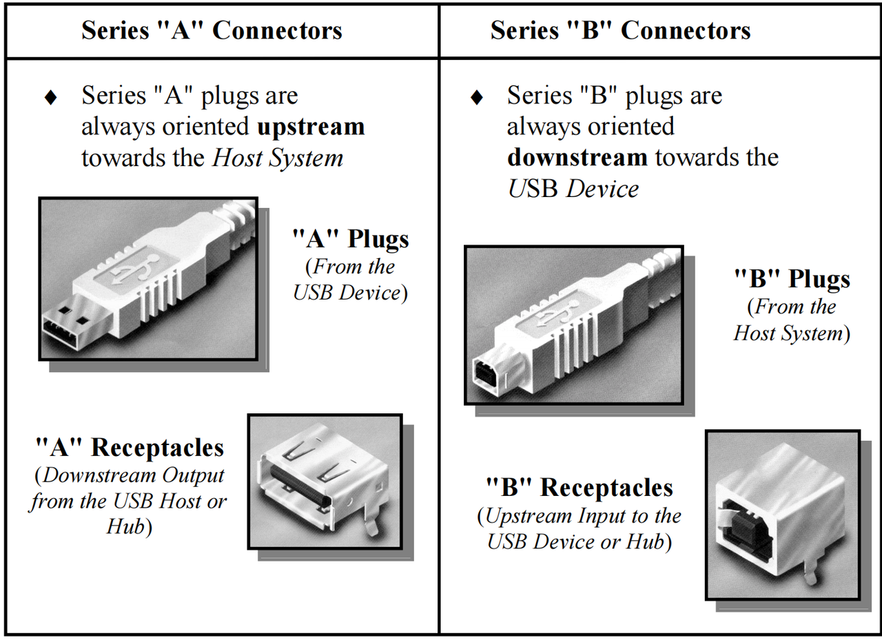
The figure below lists some common USB connectors.
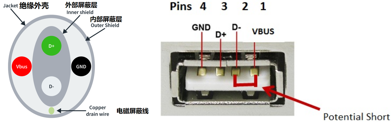
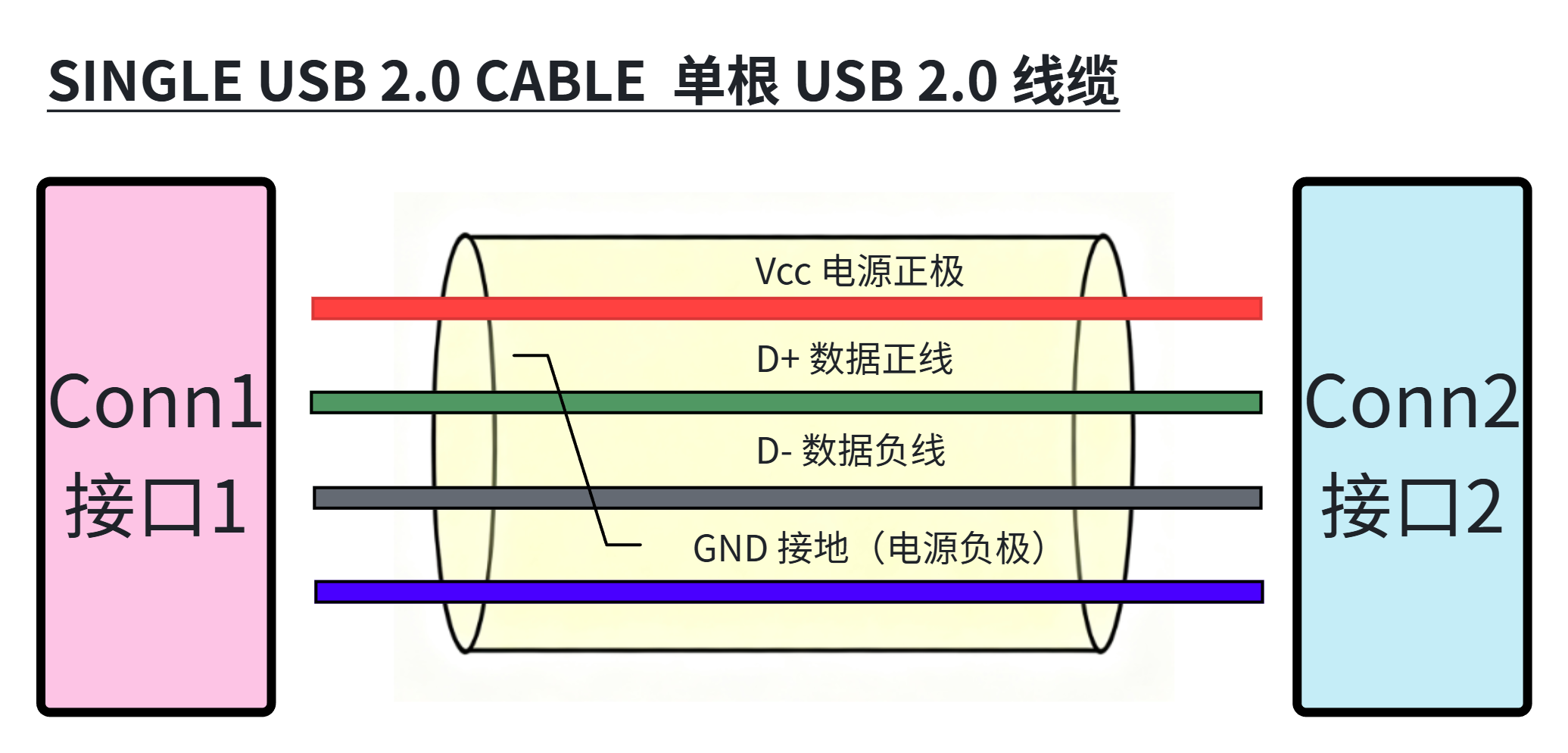
Standard USB 2.0 interfaces and cables are 4-wire, where VBUS and GND are the power line and ground line, used to power some USB devices. VBUS usually provides 5V voltage. D+ and D- are a pair of differential twisted-pair wires used to transmit data. This is somewhat similar to the 485 serial port we mentioned in serial communication, except that the voltage on the wires is different. The advantage of using differential signals is that these signals are not easily affected by electromagnetic interference from surrounding devices. They also do not emit electromagnetic radiation that might affect surrounding electronic devices. This is very important because the USB protocol is designed to work around sensitive devices such as microprocessors and microcontrollers.
Later, for USB OTG devices, Mini-type and Micro-type connectors were introduced, and the cables and connectors changed from four wires to five wires. The extra wire is marked as the ID signal line, used to distinguish the identity of the device:
When the ID line is grounded: it indicates that the device's initial identity is a host, i.e., an A-type device
When the ID line is floating or connected high: it indicates that the device's initial identity is a device, i.e., a B-type device
The USB host can power devices through the VBUS wire on the cable. Devices can be divided into the following two types according to whether they need current provided by the host:
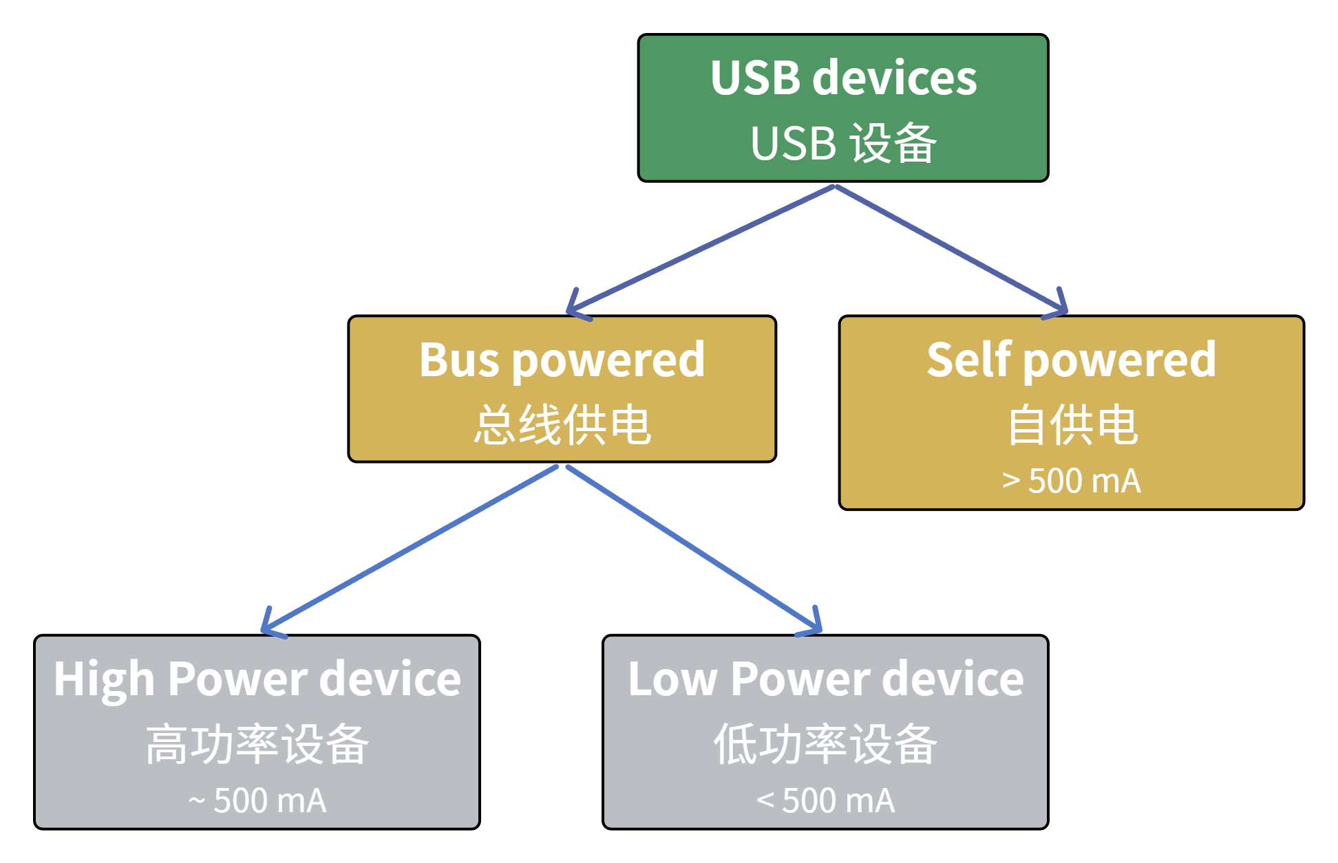
"bus-powered" devices: devices that obtain current from VBUS are called "bus-powered" devices. This category can be further divided into high-power devices and low-power devices:
High-power devices: devices that need about 500ma of current
Low-power devices: devices that need less than 500ma of current
"self-powered" devices: devices that choose self-powering are called "self-powered" devices
Note that devices cannot power the host; that is, a device's VBUS line cannot push current into the bus.
USB is a hot-pluggable communication bus. In the USB protocol, the host can detect whether a device is plugged in by monitoring the level changes on the D+ and D- lines: after a USB device is connected, it pulls the D+ and D- signal lines up to a specific level combination. The host monitors the level states of the D+ and D- lines and identifies the connected device type according to the different level combinations.
Let's look at a common circuit diagram of the host-side connection with a device:
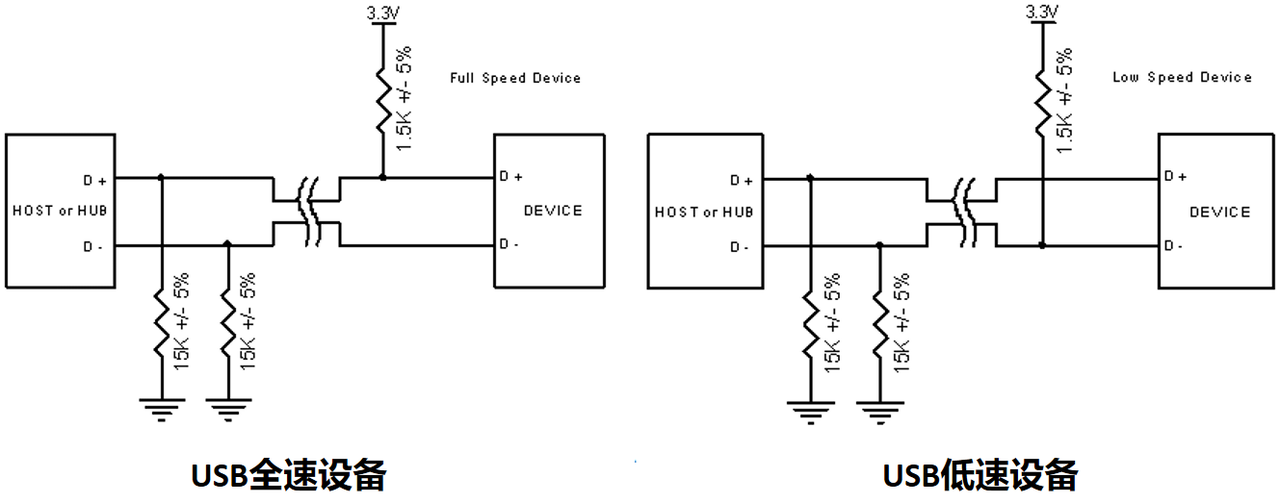
You can see that on the port of the host or hub, the D+ and D- differential signal lines are both pulled down to ground by a 1.5K resistor.
For USB devices, there are two cases:
For low-speed devices: the D- signal line is pulled up with a 1.5K resistor
For high-speed/full-speed devices: the D+ signal line is pulled up with a 1.5K resistor
When a device is plugged into the port, the level on the signal line with the pull-up resistor is divided by the pull-up and pull-down resistors. From the connector's perspective, this is a high-level signal, so the hub detects that a device is plugged in. It reports this signal directly or through an upstream hub to the host, and then the host determines the communication rate of the newly inserted device based on the level on D+ or D-.